EP0838403B1 - Procédé et dispositif pour couper un film protecteur dans la région couvrant des joints et des nervures de carrosseries de véhicules - Google Patents
Procédé et dispositif pour couper un film protecteur dans la région couvrant des joints et des nervures de carrosseries de véhicules Download PDFInfo
- Publication number
- EP0838403B1 EP0838403B1 EP97117202A EP97117202A EP0838403B1 EP 0838403 B1 EP0838403 B1 EP 0838403B1 EP 97117202 A EP97117202 A EP 97117202A EP 97117202 A EP97117202 A EP 97117202A EP 0838403 B1 EP0838403 B1 EP 0838403B1
- Authority
- EP
- European Patent Office
- Prior art keywords
- cutting
- protective film
- knife
- tool
- joint
- Prior art date
- Legal status (The legal status is an assumption and is not a legal conclusion. Google has not performed a legal analysis and makes no representation as to the accuracy of the status listed.)
- Expired - Lifetime
Links
- 238000005520 cutting process Methods 0.000 title claims description 94
- 230000001681 protective effect Effects 0.000 title claims description 72
- 238000000034 method Methods 0.000 title claims description 18
- 230000033001 locomotion Effects 0.000 claims description 30
- 239000011324 bead Substances 0.000 claims description 29
- 238000003825 pressing Methods 0.000 claims description 19
- 239000004033 plastic Substances 0.000 claims description 11
- 229920003023 plastic Polymers 0.000 claims description 11
- 239000000463 material Substances 0.000 claims description 9
- 239000011248 coating agent Substances 0.000 claims description 6
- 238000000576 coating method Methods 0.000 claims description 6
- 238000002844 melting Methods 0.000 claims description 4
- 230000008018 melting Effects 0.000 claims description 4
- 238000005259 measurement Methods 0.000 claims description 2
- 238000011144 upstream manufacturing Methods 0.000 claims 2
- 230000001939 inductive effect Effects 0.000 claims 1
- 230000000007 visual effect Effects 0.000 claims 1
- 239000003973 paint Substances 0.000 description 8
- 239000000523 sample Substances 0.000 description 7
- 238000004519 manufacturing process Methods 0.000 description 5
- 239000000853 adhesive Substances 0.000 description 4
- 239000011888 foil Substances 0.000 description 3
- 238000010422 painting Methods 0.000 description 3
- 239000006223 plastic coating Substances 0.000 description 3
- 230000037303 wrinkles Effects 0.000 description 3
- 238000003860 storage Methods 0.000 description 2
- 230000009182 swimming Effects 0.000 description 2
- 208000010201 Exanthema Diseases 0.000 description 1
- 230000001070 adhesive effect Effects 0.000 description 1
- 239000002313 adhesive film Substances 0.000 description 1
- 230000037237 body shape Effects 0.000 description 1
- 230000001680 brushing effect Effects 0.000 description 1
- 238000013461 design Methods 0.000 description 1
- 208000018459 dissociative disease Diseases 0.000 description 1
- 230000000694 effects Effects 0.000 description 1
- 230000007613 environmental effect Effects 0.000 description 1
- 201000005884 exanthem Diseases 0.000 description 1
- 238000002474 experimental method Methods 0.000 description 1
- 239000012530 fluid Substances 0.000 description 1
- 230000012010 growth Effects 0.000 description 1
- 238000010438 heat treatment Methods 0.000 description 1
- 238000002347 injection Methods 0.000 description 1
- 239000007924 injection Substances 0.000 description 1
- 238000003780 insertion Methods 0.000 description 1
- 230000037431 insertion Effects 0.000 description 1
- 238000007689 inspection Methods 0.000 description 1
- 239000000155 melt Substances 0.000 description 1
- 230000003287 optical effect Effects 0.000 description 1
- 238000004091 panning Methods 0.000 description 1
- 206010037844 rash Diseases 0.000 description 1
- 239000002904 solvent Substances 0.000 description 1
- 238000003892 spreading Methods 0.000 description 1
- 238000012546 transfer Methods 0.000 description 1
Images

Classifications
-
- B—PERFORMING OPERATIONS; TRANSPORTING
- B65—CONVEYING; PACKING; STORING; HANDLING THIN OR FILAMENTARY MATERIAL
- B65B—MACHINES, APPARATUS OR DEVICES FOR, OR METHODS OF, PACKAGING ARTICLES OR MATERIALS; UNPACKING
- B65B11/00—Wrapping, e.g. partially or wholly enclosing, articles or quantities of material, in strips, sheets or blanks, of flexible material
- B65B11/02—Wrapping articles or quantities of material, without changing their position during the wrapping operation, e.g. in moulds with hinged folders
-
- B—PERFORMING OPERATIONS; TRANSPORTING
- B29—WORKING OF PLASTICS; WORKING OF SUBSTANCES IN A PLASTIC STATE IN GENERAL
- B29C—SHAPING OR JOINING OF PLASTICS; SHAPING OF MATERIAL IN A PLASTIC STATE, NOT OTHERWISE PROVIDED FOR; AFTER-TREATMENT OF THE SHAPED PRODUCTS, e.g. REPAIRING
- B29C63/00—Lining or sheathing, i.e. applying preformed layers or sheathings of plastics; Apparatus therefor
- B29C63/0056—Provisional sheathings
-
- B—PERFORMING OPERATIONS; TRANSPORTING
- B29—WORKING OF PLASTICS; WORKING OF SUBSTANCES IN A PLASTIC STATE IN GENERAL
- B29C—SHAPING OR JOINING OF PLASTICS; SHAPING OF MATERIAL IN A PLASTIC STATE, NOT OTHERWISE PROVIDED FOR; AFTER-TREATMENT OF THE SHAPED PRODUCTS, e.g. REPAIRING
- B29C63/00—Lining or sheathing, i.e. applying preformed layers or sheathings of plastics; Apparatus therefor
- B29C63/0082—Finishing the edges of holes or perforations in the lined product
-
- B—PERFORMING OPERATIONS; TRANSPORTING
- B29—WORKING OF PLASTICS; WORKING OF SUBSTANCES IN A PLASTIC STATE IN GENERAL
- B29C—SHAPING OR JOINING OF PLASTICS; SHAPING OF MATERIAL IN A PLASTIC STATE, NOT OTHERWISE PROVIDED FOR; AFTER-TREATMENT OF THE SHAPED PRODUCTS, e.g. REPAIRING
- B29C63/00—Lining or sheathing, i.e. applying preformed layers or sheathings of plastics; Apparatus therefor
- B29C63/0082—Finishing the edges of holes or perforations in the lined product
- B29C63/0086—Finishing the edges of holes or perforations in the lined product and removing the portion of the lining covering the holes
-
- B—PERFORMING OPERATIONS; TRANSPORTING
- B29—WORKING OF PLASTICS; WORKING OF SUBSTANCES IN A PLASTIC STATE IN GENERAL
- B29C—SHAPING OR JOINING OF PLASTICS; SHAPING OF MATERIAL IN A PLASTIC STATE, NOT OTHERWISE PROVIDED FOR; AFTER-TREATMENT OF THE SHAPED PRODUCTS, e.g. REPAIRING
- B29C63/00—Lining or sheathing, i.e. applying preformed layers or sheathings of plastics; Apparatus therefor
- B29C63/02—Lining or sheathing, i.e. applying preformed layers or sheathings of plastics; Apparatus therefor using sheet or web-like material
-
- B—PERFORMING OPERATIONS; TRANSPORTING
- B62—LAND VEHICLES FOR TRAVELLING OTHERWISE THAN ON RAILS
- B62D—MOTOR VEHICLES; TRAILERS
- B62D65/00—Designing, manufacturing, e.g. assembling, facilitating disassembly, or structurally modifying motor vehicles or trailers, not otherwise provided for
-
- B—PERFORMING OPERATIONS; TRANSPORTING
- B65—CONVEYING; PACKING; STORING; HANDLING THIN OR FILAMENTARY MATERIAL
- B65B—MACHINES, APPARATUS OR DEVICES FOR, OR METHODS OF, PACKAGING ARTICLES OR MATERIALS; UNPACKING
- B65B33/00—Packaging articles by applying removable, e.g. strippable, coatings
- B65B33/04—Packaging large articles, e.g. complete machines, aircraft
-
- B—PERFORMING OPERATIONS; TRANSPORTING
- B65—CONVEYING; PACKING; STORING; HANDLING THIN OR FILAMENTARY MATERIAL
- B65B—MACHINES, APPARATUS OR DEVICES FOR, OR METHODS OF, PACKAGING ARTICLES OR MATERIALS; UNPACKING
- B65B41/00—Supplying or feeding container-forming sheets or wrapping material
- B65B41/12—Feeding webs from rolls
- B65B41/14—Feeding webs from rolls by grippers
-
- B—PERFORMING OPERATIONS; TRANSPORTING
- B65—CONVEYING; PACKING; STORING; HANDLING THIN OR FILAMENTARY MATERIAL
- B65B—MACHINES, APPARATUS OR DEVICES FOR, OR METHODS OF, PACKAGING ARTICLES OR MATERIALS; UNPACKING
- B65B61/00—Auxiliary devices, not otherwise provided for, for operating on sheets, blanks, webs, binding material, containers or packages
- B65B61/02—Auxiliary devices, not otherwise provided for, for operating on sheets, blanks, webs, binding material, containers or packages for perforating, scoring, slitting, or applying code or date marks on material prior to packaging
-
- B—PERFORMING OPERATIONS; TRANSPORTING
- B65—CONVEYING; PACKING; STORING; HANDLING THIN OR FILAMENTARY MATERIAL
- B65B—MACHINES, APPARATUS OR DEVICES FOR, OR METHODS OF, PACKAGING ARTICLES OR MATERIALS; UNPACKING
- B65B61/00—Auxiliary devices, not otherwise provided for, for operating on sheets, blanks, webs, binding material, containers or packages
- B65B61/04—Auxiliary devices, not otherwise provided for, for operating on sheets, blanks, webs, binding material, containers or packages for severing webs, or for separating joined packages
- B65B61/06—Auxiliary devices, not otherwise provided for, for operating on sheets, blanks, webs, binding material, containers or packages for severing webs, or for separating joined packages by cutting
-
- B—PERFORMING OPERATIONS; TRANSPORTING
- B29—WORKING OF PLASTICS; WORKING OF SUBSTANCES IN A PLASTIC STATE IN GENERAL
- B29C—SHAPING OR JOINING OF PLASTICS; SHAPING OF MATERIAL IN A PLASTIC STATE, NOT OTHERWISE PROVIDED FOR; AFTER-TREATMENT OF THE SHAPED PRODUCTS, e.g. REPAIRING
- B29C2793/00—Shaping techniques involving a cutting or machining operation
-
- Y—GENERAL TAGGING OF NEW TECHNOLOGICAL DEVELOPMENTS; GENERAL TAGGING OF CROSS-SECTIONAL TECHNOLOGIES SPANNING OVER SEVERAL SECTIONS OF THE IPC; TECHNICAL SUBJECTS COVERED BY FORMER USPC CROSS-REFERENCE ART COLLECTIONS [XRACs] AND DIGESTS
- Y10—TECHNICAL SUBJECTS COVERED BY FORMER USPC
- Y10T—TECHNICAL SUBJECTS COVERED BY FORMER US CLASSIFICATION
- Y10T156/00—Adhesive bonding and miscellaneous chemical manufacture
- Y10T156/10—Methods of surface bonding and/or assembly therefor
- Y10T156/1002—Methods of surface bonding and/or assembly therefor with permanent bending or reshaping or surface deformation of self sustaining lamina
- Y10T156/1028—Methods of surface bonding and/or assembly therefor with permanent bending or reshaping or surface deformation of self sustaining lamina by bending, drawing or stretch forming sheet to assume shape of configured lamina while in contact therewith
-
- Y—GENERAL TAGGING OF NEW TECHNOLOGICAL DEVELOPMENTS; GENERAL TAGGING OF CROSS-SECTIONAL TECHNOLOGIES SPANNING OVER SEVERAL SECTIONS OF THE IPC; TECHNICAL SUBJECTS COVERED BY FORMER USPC CROSS-REFERENCE ART COLLECTIONS [XRACs] AND DIGESTS
- Y10—TECHNICAL SUBJECTS COVERED BY FORMER USPC
- Y10T—TECHNICAL SUBJECTS COVERED BY FORMER US CLASSIFICATION
- Y10T156/00—Adhesive bonding and miscellaneous chemical manufacture
- Y10T156/10—Methods of surface bonding and/or assembly therefor
- Y10T156/1002—Methods of surface bonding and/or assembly therefor with permanent bending or reshaping or surface deformation of self sustaining lamina
- Y10T156/1034—Overedge bending of lamina about edges of sheetlike base
Definitions
- the invention relates to a method and an apparatus for Cut through protective film in the area of taped joints and Beading, especially of car bodies.
- the vehicles be prepared for shipping in such a way that they do not Damage, especially that the painting due to storage and weather conditions are not affected.
- the vehicles Be for the transfer of customers by train or even ship transport necessary, the vehicles have a wax protection layer for this coated, which is removed again before customer delivery had to become.
- the residue-free removal of the protective wax was not just a labor-intensive job, it was stressful also people and the environment because of the solvents used. That is why the bodywork has recently been adopted during transport with self-adhesive films protect, but only the weather and deposit-endangered essentially horizontal surface areas protected the body. This degree of protection is very effective, but also relatively expensive, so that they not only as protection during transportation, but also provided as protection during vehicle assembly and accordingly the protective film before the final assembly of the vehicle, i.e. applied immediately after painting the body.
- This piece of protective film was made by the two, four or several people hands-free with the self-adhesive side freely stretched downwards, so over the body spent, there in a horizontal position on the associated surface area lowered according to position, more or less foldable and created bubble-free and by brushing with a soft, slippery object, e.g. a stiffened piece of felt pressed.
- a soft, slippery object e.g. a stiffened piece of felt pressed.
- the protective film was included manually cut through a knife and cut the edges of Hand pressed to carry out assembly-related work to design. Fiddling with a sharp-edged knife in the immediate vicinity of the painted body surface the hustle and bustle again and again to paint damage despite ongoing practice and led to extensive rework. Especially at Body shapes, for example in the area of the hood Have beads, a manual cut of the Beading spanning section of film so far only after underlaying a film strip because there is a risk of damage to the paint was too large in the bead area.
- JP 06 156 339 A is also a device for applying self-adhesive Foil known on surface areas of motor vehicle bodies, the outstanding Edge portions of the applied film by one arranged on an industrial robot Cutting tool can be separated.
- the object of the present invention is a method for cutting through protective film in the area covered with adhesive
- the object of the present invention is a method for cutting through protective film in the area covered with adhesive
- the monotonous manual work through automation replaced helps prevent paint damage and which can also save personnel costs.
- the method to be provided or the method to be provided Device for use with the in the German Patent Application 196 42 831.9 mentioned above Invention may be suitable.
- a film supply is used for example with a robot-guided stenter a measured piece of film is removed and crease-free and under a certain internal stress in the stenter.
- a perforation tool that is also robot-guided Perforation lines in the film cut laid that a certain removal due to assembly Film areas by tearing along the perforation lines enable. Only then is the one with the perforation lines provided film cut by the stenter robot in the correct position lowered to the associated surface area of the body and pressed on them without wrinkles or bubbles.
- the film is according to the invention severed by means of a robot-guided knife, the Cutting edges, for example with a rotating brush or an air nozzle.
- the device according to the invention is characterized by a free programmable industrial robots (slicing robots) with at least five degrees of freedom, on its working arm a cutting and pressing tool is attached.
- a cutting tool is a knife with a blade to cut through the Protective film provided in the area of taped joints and beads.
- a suitable is for pressing the cut edges of the protective film Press tool provided that the cutting tool in Cutting and movement direction is subordinate. It acts it is either a rotating brush according to the invention, the can be placed on the body parts covered with the protective film or around an air nozzle directed towards the cut edges, whose preferably diffuse air jet presses the edges.
- the use of the slicing robot ensures precise guidance the knife to cut through the protective film, so that the risk of damage to the paint is greatly reduced becomes.
- the slicing robot pushes the one arranged on its working arm Knife blade in the area of a glued joint or Bead through the protective film and move the knife in the direction a cutting and movement direction predetermined by the joint or bead until the end of the joint or bead is reached is.
- rotating brush directly or by lowering the working arm placed on the body part covered with protective film the cut edges of the severed Protective film pressed against the body so that it comes off the film due to protective film edges not adhering to the body is excluded.
- the cut edges are arranged downstream of the knife Air nozzle that is directed towards the protective film diffuses airflow, pressed against the body.
- the flat sides of the knife blade have each have a plastic coating.
- a plastic coating will damage the painted body through contact of the hard blade material with the paint in case of a slight deviation of the Avoid knife guiding direction from joint alignment.
- the plastic applied to both sides of the blade should be good Sliding properties compared to hardened vehicle paints and compared to the protective film to be applied.
- the knife is in the Cutting and pressing tool using a leaf spring transverse to Cutting and moving direction suspended elastically.
- a leaf spring transverse to Cutting and moving direction suspended elastically.
- Knife can be swiveled backwards in the cutting direction during the cutting process arranged. If the knife is in the cutting process Cutting direction encounter an unforeseen obstacle, see above it is pivoted backwards in the cutting direction. This panning is perceived and effected by a suitable sensor an immediate withdrawal of the knife or the working arm of the slicing robot so that a knife in it Cutting path opposing unforeseen and undesirable Obstacle not to a standstill of the production line leads. Rather, the slicing robot drives to the next one Body joint or bead and cuts them open as planned. Protective films that are not properly cut are then removed treated by a subordinate manual inspection station. Alternatively, the slicing robot can be pulled back skip the point of the obstacle and behind the obstacle, the knife again through the protective film Pierce over the joint to be cut in order to cut through to continue.
- the knife is vertical to the film level and across the cutting and moving direction adjustable on a two-axis floating sled.
- the swimming sledge is in turn on the working arm of the robot arranged and allowed during the "search run” make a fine adjustment of the Knife in the z direction, i.e. perpendicular to the film plane.
- the z-float is fixed during this search run and the knife is extended. This extension can both by moving the slicing robot's working arm perpendicular to the film plane as well as by directly extending the Knives are made. This is followed by the cutting process at, with inaccuracies between the robot-guided Cutting path of the knife and the body joint through the y floating slide be balanced.
- the cutting and pressing tool can be moved into different working positions and a measuring device assigned to the cutting and pressing tool to record the actual position of the joints to be cut or beads of the body within the working space of the slicing robot is provided.
- the measuring device is, for example, a and pressing tool arranged measuring tool, and the cutting and pressure tool is in different working positions pivotable, the measuring tool in a first pivot position is effective and in a second swivel position Cutting and pressing tool.
- the measuring tool can advantageously comprise optical and / or acoustic sensors, by means of which the exact position of the to be cut Gap can be detected. As soon as the actual position of the gap has been determined, the cutting and pressing tool becomes like this pivoted that the knife to the detected actual position of the Gap is aligned and the cutting process can begin.
- In another embodiment of the invention is as a measuring device one on a two-axis floating sled perpendicular to the film plane as well as adjustable across the cutting and movement direction tactile button provided.
- This button can by lower the robot arm and / or directly onto the body through which the z-sledge (perpendicular to the Film level) is deflected. The robot then carries along the tactile button is essentially transverse to the alignment of the joint ongoing movement through. As soon as the button is in the The gap of the joint is when the robot continues the y floating sled (transverse to the cutting and moving direction) deflected, the button remains in the gap. To At the end of the search run, the z-float is fixed. Due to the actual position of the cut to be cut Fuge can now move the knife to the starting position the cutting process.
- Knife on the two-axis floating sled holding the button arranged and the button and the knife are perpendicular to Foil level adjustable.
- the knife can simply be extended, making it the Protective film covering the gap pierces and the button is pressed retracted so that the cutting process by the robot guide of the knife can begin.
- the push button is deflected as soon as it is pressed at the essentially transverse to the gap to be cut Search drive enters the gap.
- the deflection will detected by a suitable sensor and a signal on the slicing robot which transmits the deflection point as The insertion point for the knife saves.
- One detected once Deflection or a determined deflection path can be saved also used for an adjacent body joint or bead become.
- the tactile button has a rounded tip.
- the tactile button has a probe tip with a probe roller adapted to the gap.
- the object on which the invention is based becomes a device for cutting protective film in the area sealed joints and beads with the features of the claim 14 proposed. Accordingly, there is one on the working arm Slicing robot as a cutting and pressing tool an air nozzle arranged to diffuse hot air is suitable, the temperature of the hot air for example at least the melting temperature of the plastic of the protective film corresponds.
- the device according to the invention allows one contact-free cutting of protective film in the area of pasted over Joints and beads, because the hot air melts the Plastic of the protective film takes place in the area of a Joint or corrugation due to the impulse of the impinging air flow is severed.
- the particular advantage of this non-contact Cutting consists in that for pressing the cut edges no additional pressure tool is required on the protective film is because of the airflow emerging from the air nozzle the cut edges are already pressed against the body. Since the hot air is diffused from the air nozzle, i.e. that it is not a punctual, but only flat air jet, it is not necessarily necessary to fine-tune the air nozzle Measuring device to be provided, as possible small deviations of the gap to be cut from the actual position by the diffuse airflow can be compensated.
- a mandrel made of a good material Thermal conductivity arranged in the area in front of the air outlet opening the air nozzle.
- This mandrel is advantageous extendable and serves to cut through protective film especially in the area of wide beads if the through the Airflow imposed on the protective film due to the Width of the gap under the film is not sufficient, to cut them.
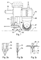
- Figure 1 shows a side view of a robot-guided robot according to the invention Device with a cutting and pressing tool and this associated measuring tool.
- Figure 2a shows an enlarged side view of a knife blade partially coated with plastic.
- Figure 2b shows the knife blade of Figure 2a in a front view.
- Figure 2c shows the knife blade of Figure 2b when severed of protective film in the area of a glued joint.
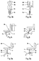
- Figures 3a and 3b show a schematic representation in side and front view of the holder of the invention Knife by means of a leaf spring.
- Figure 4 shows a schematic representation of an inventive Holder of a knife by means of a biaxial Floating sled.
- Figures 5a and 5b show a schematic representation of an inventive Measuring device with tactile probe during the Search run in motion across a fugue.
- Figure 6 shows a measuring device according to the invention with a Tactile buttons that can be swiveled transversely to the direction of the joint.
- Figure 7 shows the invention in a highly schematic representation Cut a protective film in the area of a covered joint using a hot air nozzle.
- a first embodiment of a device according to the invention is shown in Figure 1.
- the device according to the invention includes a freely programmable, not shown Industrial robots (slicing robots) with preferably six Degrees of freedom for one working arm 81 and another, seventh movement axis for moving the slicing robot along a floor guide of the production line.
- Industrial robots slicing robots
- the slicing robot with a Travel axis equipped along the mentioned floor guide.
- the task of one or more stationary Slicing robots without seventh axes of motion if the robots only work on parts of the body have to.
- the actual position is determined of the joints 6 to be cut by the cutting robot himself, who works here as a measuring robot.
- the first swivel position of the tool is the measuring tool 82 effective with which the exact actual position of the body 1 or Joints 6 can be detected in relation to the slicing robot.
- This is effective in the second swivel position of the double tool tool part is as a cutting and pressing tool 83 formed, which a knife 79 for cutting the protective film 23 in the joint area (see FIG. 2c) and a rotating one Has brush 87 for pressing the cut edges.
- Knife 79 includes a blade 84 and a blade holder 94, so that a simple change of the blade 84 is possible.
- the Rotating brush 87 is from an electric motor 88 speed-reducing angular gear can be driven.
- alternative to of the rotating brush 87 shown can be used to press the Cut edges also one directed towards the cut edges Air jet emitting air flow can be used.
- the knife 79 is transverse to the cutting and moving direction a leaf spring 85 resiliently suspended so that there is any Positional deviations of the joint from the one specified by the robot Can easily follow the guideway.
- a leaf spring 85 resiliently suspended so that there is any Positional deviations of the joint from the one specified by the robot Can easily follow the guideway.
- the freedom of movement can be specified by adjusting screws 92.
- Figure 4 shows a schematic representation of the storage of Knife 79 on a two-axis float 95, the on the working arm 81 of the slicing robot is arranged.
- the biaxial floating slide 95 includes one perpendicular to the film plane movable z-slide Z and a perpendicular to the z-slide Z and across the cutting and moving direction movable y-slide Y.
- the knife is on the y-slide Y. 79 for cutting through the protective film 23.
- the pressing tool (rotating brush 87) is in the representation of the figure 4 not shown for reasons of clarity - it can also be cut and moved on the Y-slide behind the knife 79 or even because it has sufficient Width to cover possible tolerances, directly be attached to the working arm 81.
- a suitable measuring device of the slicing robot of the z-slide Z set so that the working arm only one defined short distance to pierce the protective film in the z direction must proceed.
- the y-slide is Y also advantageously determined, but is before the start the cutting process solved so that it by its swimming movement Possible joint tolerances or deviations in the y direction can compensate in the course of the joint from the target position, the Knife blade 84 is vertical in each position of the y-slide Y. to the slide level.
- the arrangement of the knife 79 on the described two-axis floating sled 95 can with or without the bracket on a leaf spring and the other components, as described above with reference to FIGS. 1, 2 and 3 has been described.
- Figure 5 shows a measuring device according to the invention, by means of which determine the piercing position of the knife blade 84 can.
- a tactile button 96 with a rounded tip 97 is arranged on the y-slide Y essentially perpendicular to the plane of the film .
- the two-axis floating slides 95 attached to the working arm 81 lowered to the body 1 until the button 96 with his Probe tip 97 acts on the body 1 ( Figure 5a).
- the slicing robot introduces one with its working arm 81 essentially transverse to the orientation of the joint to be determined 6 movement through until the tactile button 96 with his probe tip 97 engages in the joint 6. This will do so registers that with a further movement of the biaxial Floating slide 95 the y-slide Y experiences a rash and displays.
- the position of the y-slide Y determined in this way is then used to determine the actual position of the joint 6 and to pierce the knife 79 through the protective film 23.
- the knife 79 is aligned in the cutting and moving direction arranged behind the tactile button 96, and preferably also on the y-slide Y.
- Both include the tactile button 96 and the knife 79 separately from each other adjustable in z-direction so that by extending the Knife 79 in the z direction, the protective film is pierced, and after raising the tactile button 96 also in the z direction the cutting process can begin.
- the deflection of the y-slide Y compared to that stored in the slicing robot Target position determined and the injection point of the Knife corrected accordingly.
- FIG. Therefore Another possibility for a measuring device to find The joint 6 to be cut is shown in FIG. Therefore is a probe connected to a tactile measuring system 96 'provided with a feeler roller 97'.
- the button 96 ' is by means of a suitable holder with the working arm 81 of the slicing robot connected, being transverse to the bracket 98 arranged pivotably to the cutting and movement direction is.
- the button 96 ' lowered to the body 1 as described above and proceed essentially transversely to the joint 6 to be determined.
- the button 96 'with its feeler roller 97' into the joint 6 engages occurs when the working arm 81 moves further a pivoting of the button 96 'on the bracket 98 is registered by means of a suitable sensor.
- the working arm 81 ends its essentially transverse to the joint 6 Movement and the position of the button 96 'is called the piercing position saved for the knife 79.
- the Button 96 'from its position acting on the body 1 retracted / pivoted back and the cutting and pressing tool is brought into its active position and the knife blade 84 at the saved position through the protective film 23 engraved.
- buttons 96 'shown in FIG. 6 can also be used a rounded probe tip (see FIG. 5) can be used, just like the feeler roller 97 'also in connection with that in figure 5 button 96 shown can be used.
- Figure 7 shows another in a highly schematic representation Embodiment of an inventive device for Cut through protective film.
- the device shown comprises one on a working arm, not shown described slicing robot arranged with air nozzle 100 an air outlet opening 102.
- the air nozzle 100 is with its Air outlet opening essentially perpendicular to the body surface aligned and is by means of the working arm of the Cutting robot spaced apart from the body 1 via a with protective film 23 pasted over, joint 6 to be cut free.
- the air nozzle 100 radiates through its air outlet opening 102 a diffuse air jet, which is indicated by the arrows in FIG is illustrated.
- the temperature of the air outlet opening 102 exiting air is chosen to interact with the exit velocity of the air, i.e. of pressure exerted by the air on the film, a softening of the plastic and its severing.
- the temperature of the air outlet opening 102 exiting air is chosen to interact with the exit velocity of the air, i.e. of pressure exerted by the air on the film, a softening of the plastic and its severing.
- the temperature was about 100 ° to 160 ° C in Connection with a pressure of 6 to 1 bar.
- the movement of the Air nozzle 100 is done at a speed that is sufficient is slow that the plastic in the area of the joint 6 by heating (Softening or melting) and exposure to the air flow is severed so that after completing the movement the air nozzle 100 is cut free along the joint 6.
- the advantage of the severing device shown in FIG. 7 consists in the fact that no separate pressing tool is necessary is because the cut edges of the protective film 23 by the Airflow not only cuts through, but at the same time to the Body 1 are pressed. Furthermore, there is no additional one Measuring device required for fine determination of the gap position, because possible tolerances of the diffuse air flow exact joint course can be compensated.
- a mandrel made of a material good thermal conductivity can be arranged by the protective film 23 is stung if the bead is so wide that the Protective film 23 by the impulse exerted by the air flow cannot be severed.
- Piercing the protective film 23 through the mandrel is done, for example, by a corresponding one Lowering the air nozzle 100.
- the mandrel is advantageously on the air nozzle 100 extendable so that the distance between the protective film and the air nozzle for piercing the Protective film with the mandrel does not have to be changed.
Landscapes
- Engineering & Computer Science (AREA)
- Mechanical Engineering (AREA)
- Manufacturing & Machinery (AREA)
- Chemical & Material Sciences (AREA)
- Combustion & Propulsion (AREA)
- Transportation (AREA)
- Lining Or Joining Of Plastics Or The Like (AREA)
- Nonmetal Cutting Devices (AREA)
- Manipulator (AREA)
- Details Of Cutting Devices (AREA)
- Automobile Manufacture Line, Endless Track Vehicle, Trailer (AREA)
Claims (26)
- Procédé pour sectionner du film protecteur dans la zone où il est collé en recouvrement de joints ou de nervures en creux, notamment de carrosseries de véhicules automobiles, à l'aide d'un robot de coupe à au moins cinq degrés de liberté du mouvement et à commande librement programmable, qui, au moyen d'un outil de coupe (83, 79) disposé sur son bras de travail (81), transperce le film protecteur (23) à une extrémité d'un joint (6) ou d'une nervure en creux devant être dégagé par coupe, et qui, par un mouvement de l'outil de coupe (83, 79) le long d'une direction de coupe et de mouvement coïncidant avec le tracé du joint (6) ou de la nervure en creux, sectionne le film protecteur (23) sensiblement sur toute la longueur du joint (6) ou de la nervure en creux, les bords de coupe du film protecteur (23) sectionné étant pressés sur la carrosserie (1), au moyen d'un outil d'application (83, 87) placé à la suite de l'outil de coupe (83, 79) sur le bras de travail (81).
- Procédé selon la revendication 1, caractérisé en ce qu'en guise d'outil de coupe, il est prévu un couteau (79) et en guise d'outil d'application, une brosse rotative (87) ou une buse d'air (100).
- Procédé selon la revendication 1 ou 2, caractérisé en ce que l'outil de coupe (83, 79), à l'instant du transpercement du film protecteur (23), est maintenu dans une orientation définie par rapport au bras de travail (81), et, durant l'opération de coupe, est maintenu de manière à pouvoir fléchir transversalement à la direction de coupe et de mouvement, s'il entre en contact avec des parties de carrosserie délimitant le joint (6) ou la nervure en creux.
- Procédé selon l'une des revendications 1 à 3, caractérisé en ce que l'outil de coupe (83, 79), s'il bute sur un obstacle durant l'opération de coupe, est retiré de sa position de transpercement du film protecteur (23).
- Procédé selon l'une des revendications 1 à 4, caractérisé en ce qu'avant l'opération de coupe on détermine la position réelle du joint (6) à dégager par coupe, au moyen d'un dispositif de mesure approprié, associé à l'outil de coupe et d'application (83, 79, 87).
- Procédé selon la revendication 5, caractérisé en ce que pour déterminer la position réelle du joint (6) à dégager par coupe, un palpeur (96, 96') placé sur le bras de travail (81), est abaissé sur la carrosserie (1) dans la zone d'une première extrémité du joint (6) à dégager par coupe, et est déplacé sensiblement de manière transversale au joint (6) jusqu'à ce qu'il s'engage dans le joint (6).
- Procédé selon la revendication 6, caractérisé en ce que la position du palpeur (96, 96') ayant été déterminée, est mémorisée par le robot de coupe, et l'outil de coupe (83, 79), après retrait du palpeur (96'), est amené à transpercer le film protecteur (23) au niveau de la position mémorisée.
- Procédé selon la revendication 6, caractérisé en ce que l'outil de coupe (83, 79) est disposé en alignement avec le palpeur (96), et est extrait après l'engagement du palpeur (96) dans le joint (6), pour venir transpercer le film protecteur.
- Procédé pour sectionner du film protecteur dans la zone où il est collé en recouvrement de joints ou de nervures en creux, notamment de carrosseries de véhicules automobiles, à l'aide d'un robot de coupe à au moins cinq degrés de liberté du mouvement et à commande librement programmable, qui, au moyen d'un jet d'air diffus dont la température correspond au moins à la température de fusion de la matière plastique du film protecteur (23), et sortant d'une buse d'air (100) placée sur le bras de travail (81) dudit robot, sectionne le film protecteur (23) et presse simultanément ses bords de coupe contre la carrosserie (1).
- Procédé selon la revendication 9, caractérisé en ce que dans la zone devant l'ouverture de sortie d'air (102) de la buse d'air (100) est disposé un poinçon en un matériau de bonne conductibilité thermique, qui, lors du dégagement par coupe d'une nervure en creux, est extrait et est amené à transpercer le film protecteur (23) recouvrant la nervure en creux.
- Dispositif pour sectionner du film protecteur dans la zone où il est collé en recouvrement de joints ou de nervures en creux, notamment de carrosseries de véhicules automobiles, caractérisé par un robot de coupe à au moins cinq degrés de liberté du mouvement et à commande librement programmable, sur le bras de travail (81) duquel, est placé un outil de coupe et d'application (83), qui comprend un couteau (79) avec une lame (84) pour sectionner le film protecteur (23) dans la zone où il est collé en recouvrement de joints (6) et de nervures en creux, ainsi qu'une brosse (87) en rotation ou une buse d'air (100) pour l'application des bords de coupe.
- Dispositif selon la revendication 11, caractérisé en ce que les faces planes de la lame du couteau (84) présentent chacune un revêtement de matière plastique (93).
- Dispositif selon la revendication 11 ou 12, caractérisé en ce que le couteau (84) est suspendu de manière élastique, transversalement à la direction de coupe et de mouvement, dans l'outil de coupe et d'application (83), au moyen d'un ressort à lame (84).
- Dispositif selon la revendication 13, caractérisé par des bras de butée (86) réglables, destinés à la sollicitation du couteau (84) et/ou du ressort à lame (85), transversalement à la direction de coupe et de mouvement.
- Dispositif selon l'une des revendications 11 à 14, caractérisé en ce que le couteau (84), lorsqu'il bute sur un obstacle durant l'opération de coupe, peut pivoter vers l'arrière dans la direction de coupe.
- Dispositif selon l'une des revendications 11 à 15, caractérisé en ce que le couteau (84) est disposé sur un chariot flottant à deux axes, de manière réglable perpendiculairement au plan du film ainsi que transversalement à la direction de coupe et de mouvement.
- Dispositif selon l'une des revendications 11 à 16, caractérisé en ce que l'outil de coupe et d'application (83) peut être transféré dans différentes positions de travail, et en ce qu'il est prévu un dispositif de mesure associé à l'outil de coupe et d'application (83) pour relever la position réelle du joint (6) ou de la nervure en creux de la carrosserie (1) à dégager par coupe, à l'intérieur du domaine de travail du robot de coupe (80).
- Dispositif selon la revendication 17, caractérisé en ce que le dispositif de mesure est un outil de mesure (82) disposé sur l'outil de coupe et d'application (83), et en ce qu'il est possible de faire pivoter l'outil de coupe et d'application (83) dans différentes positions de travail, l'outil de mesure (82) étant actif dans une première position de pivotement, et l'outil de coupe et d'application (83) étant actif dans une seconde position de pivotement.
- Dispositif selon la revendication 17, caractérisé en ce qu'en guise de dispositif de mesure, il est prévu sur un chariot flottant (95) à deux axes, un palpeur tactile (96) réglable perpendiculairement au plan du film ainsi que transversalement à la direction de coupe et de mouvement.
- Dispositif selon la revendication 19, caractérisé en ce que le couteau (84) est disposé de manière alignée avec le palpeur tactile (96) dans la direction de coupe et de mouvement, sur le chariot flottant (95) à deux axes supportant le palpeur tactile (96), le palpeur tactile (96) et le couteau (84) pouvant être extraits respectivement perpendiculairement au plan du film.
- Dispositif selon la revendication 17, caractérisé en ce qu'en guise de dispositif de mesure, il est prévu un palpeur (96') pouvant pivoter transversalement à la direction de coupe et de mouvement.
- Dispositif selon l'une des revendications 19 à 21, caractérisé en ce que le palpeur (96, 96') présente une pointe de palpage (97) arrondie.
- Dispositif selon l'une des revendications 19 à 21, caractérisé en ce que le palpeur (96, 96') présente une pointe de palpage comportant un galet de palpage (97') adapté à l'interstice.
- Dispositif selon la revendication 17, caractérisé en ce que le dispositif de mesure comprend des capteurs optiques, acoustiques et/ou inductifs détectant des points de mesure disposés le long de la carrosserie, en vue de la détermination de l'écart de la position réelle de la carrosserie par rapport à sa position de consigne.
- Dispositif pour sectionner du film protecteur dans la zone où il est collé en recouvrement de joints ou de nervures en creux, notamment de carrosseries de véhicules automobiles, caractérisé par un robot de coupe à commande librement programmable, et à au moins cinq degrés de liberté du mouvement, sur le bras de travail (81) duquel est prévue une buse d'air (100) destinée à éjecter de manière diffuse de l'air chaud.
- Dispositif selon la revendication 25, caractérisé par un poinçon en un matériau de bonne conductibilité thermique, disposé dans la zone devant l'ouverture de sortie d'air (102) de la buse d'air (100).
Applications Claiming Priority (6)
| Application Number | Priority Date | Filing Date | Title |
|---|---|---|---|
| DE29622887U DE29622887U1 (de) | 1996-10-17 | 1996-10-17 | Vorrichtung zum Applizieren von selbsthaftender Schutzfolie auf Karosserien |
| DE19642831A DE19642831C2 (de) | 1996-10-17 | 1996-10-17 | Verfahren und Vorrichtung zum Applizieren von selbsthaftender Schutzfolie auf Karosserien |
| DE19642831 | 1996-10-17 | ||
| DE29622887U | 1997-05-23 | ||
| DE19724040A DE19724040C2 (de) | 1996-10-17 | 1997-06-07 | Verfahren und Vorrichtung zum Durchtrennen von Schutzfolie im Bereich überklebter Fugen und Sicken von Karosserien |
| DE19724040 | 1997-06-07 |
Publications (2)
| Publication Number | Publication Date |
|---|---|
| EP0838403A1 EP0838403A1 (fr) | 1998-04-29 |
| EP0838403B1 true EP0838403B1 (fr) | 2000-03-08 |
Family
ID=27216740
Family Applications (1)
| Application Number | Title | Priority Date | Filing Date |
|---|---|---|---|
| EP97117202A Expired - Lifetime EP0838403B1 (fr) | 1996-10-17 | 1997-10-04 | Procédé et dispositif pour couper un film protecteur dans la région couvrant des joints et des nervures de carrosseries de véhicules |
Country Status (6)
| Country | Link |
|---|---|
| US (1) | US6001198A (fr) |
| EP (1) | EP0838403B1 (fr) |
| JP (1) | JP2884339B2 (fr) |
| BR (1) | BR9705054A (fr) |
| CA (1) | CA2218576A1 (fr) |
| ES (1) | ES2145546T3 (fr) |
Cited By (1)
| Publication number | Priority date | Publication date | Assignee | Title |
|---|---|---|---|---|
| CN120396054A (zh) * | 2025-07-02 | 2025-08-01 | 荣宝雨新材料科技(宁波)有限公司 | 一种汽车装饰膜高精度冲切装置 |
Families Citing this family (35)
| Publication number | Priority date | Publication date | Assignee | Title |
|---|---|---|---|---|
| US6514371B2 (en) | 2000-03-13 | 2003-02-04 | Louis K. Justin | Method and apparatus for applying adhesive film to an article |
| US6484121B1 (en) * | 2000-09-07 | 2002-11-19 | Ford Global Technologies, Inc. | System for automatically measuring paint film thickness |
| FR2818183A1 (fr) * | 2000-12-20 | 2002-06-21 | Norkappa | Outil portatif de decoupe |
| AU2002351475A1 (en) * | 2001-10-11 | 2003-06-17 | Andrew J. Bales | Automated painting system and related methods |
| DE10339067B4 (de) * | 2003-08-26 | 2005-08-18 | Daimlerchrysler Ag | Verfahren und Vorrichtung zum automatisierten Applizieren von Lackfolie auf Karosserieteile |
| JP4452691B2 (ja) * | 2005-08-04 | 2010-04-21 | リンテック株式会社 | シート切断装置及び切断方法 |
| CA2625154C (fr) | 2005-10-04 | 2011-06-07 | Nihon Shoryoku Kikai Co., Ltd. | Dispositif d'ebarbage aux ultrasons |
| JP4890868B2 (ja) * | 2006-01-18 | 2012-03-07 | リンテック株式会社 | シート切断装置及び切断方法 |
| US7873434B2 (en) * | 2006-04-12 | 2011-01-18 | Pape Ryan L | Cutting pattern manipulation and methods |
| JP5344918B2 (ja) * | 2006-07-25 | 2013-11-20 | 株式会社Rosecc | 3次元自動切断方法及び装置 |
| ES2334485B1 (es) * | 2007-04-29 | 2011-01-31 | Gpg Tecnicas De Panificacion, S.L. | Dispositivo automatico mejorado para cortar masas panificables. |
| US8375888B2 (en) * | 2007-05-07 | 2013-02-19 | Intermolecular, Inc. | Apparatus for forming films on substrates |
| US8096338B2 (en) * | 2009-09-25 | 2012-01-17 | Michael Alan Postill | Method and apparatus for applying sheet material to a vehicle |
| JP5785174B2 (ja) | 2009-10-13 | 2015-09-24 | スリーエム イノベイティブ プロパティズ カンパニー | 波形縁ニップ |
| DE102010055957A1 (de) * | 2010-12-23 | 2012-06-28 | Daimler Ag | Verfahren zum Herstellen von Kraftwagen und Kraftwagen |
| US10220537B2 (en) * | 2012-10-17 | 2019-03-05 | Saxum, Llc | Method and apparatus for display screen shield replacement |
| JP6102270B2 (ja) * | 2013-01-17 | 2017-03-29 | 株式会社村田製作所 | カット装置 |
| EP2902159A1 (fr) * | 2014-02-03 | 2015-08-05 | 3M Innovative Properties Company | Dispositif de coupe d'autoguidage |
| CN104528081B (zh) * | 2014-12-23 | 2016-07-06 | 江苏本能科技有限公司 | 汽车专用割膜器 |
| US9573350B2 (en) * | 2015-01-09 | 2017-02-21 | The Boeing Company | Devices and methods for applying surface coverings |
| CN104985627B (zh) * | 2015-07-15 | 2017-11-21 | 天津长荣印刷设备股份有限公司 | 一种伺服驱动压纸毛刷装置及其工作方法 |
| CN105235935A (zh) * | 2015-08-28 | 2016-01-13 | 芜湖市万华塑料制品有限公司 | 一种空调外壳的覆膜装置 |
| CN106553791A (zh) * | 2015-09-25 | 2017-04-05 | 广州市宝利邦德高分子材料有限公司 | 一种汽车贴膜设备及汽车贴膜方法 |
| JP6920046B2 (ja) * | 2016-10-20 | 2021-08-18 | スリーエム イノベイティブ プロパティズ カンパニー | フィルム切断用治具、及びフィルム施工方法 |
| JP6797503B2 (ja) * | 2017-03-23 | 2020-12-09 | 株式会社ナムックス | 裁断装置 |
| US10391514B2 (en) | 2017-06-21 | 2019-08-27 | Toyota Motor Engineering & Manufacturing North America, Inc. | Coating application with automated brushing |
| US10994876B2 (en) * | 2017-06-30 | 2021-05-04 | Divergent Technologies, Inc. | Automated wrapping of components in transport structures |
| DE102017118977A1 (de) * | 2017-08-18 | 2019-02-21 | Ullrich Buff | Wärmetauscherelement und Verfahren zu dessen Herstellung |
| CN108748360A (zh) * | 2018-06-06 | 2018-11-06 | 芜湖市奥尔特光电科技有限公司 | 一种能够精准导向且可避免水管脆断的水管切割装置 |
| CN110861127B (zh) * | 2019-11-15 | 2021-08-03 | 重庆阜华新能源科技有限公司 | 一种锂电池铝箔分条加工机及铝箔加工方法 |
| CN112093120B (zh) * | 2020-09-24 | 2025-05-06 | 宁波蓝圣智能科技有限公司 | 一种用于汽车零部件的贴膜装置 |
| CN112193444B (zh) * | 2020-09-28 | 2021-12-17 | 安徽省泗县瑞丰面粉有限公司 | 一种面粉自动分选包装一体设备 |
| CN114802895B (zh) * | 2022-04-18 | 2024-03-29 | 重庆邮电大学 | 一种真空式取膜、贴膜装置 |
| CN114655504B (zh) * | 2022-04-21 | 2023-07-04 | 苏州市朗电机器人有限公司 | 一种基于手机全包膜的覆膜装置及其使用方法 |
| CN117429682A (zh) * | 2023-12-06 | 2024-01-23 | 苏州华工自动化技术有限公司 | 一种电池盖板贴膜机及其工作方法 |
Family Cites Families (9)
| Publication number | Priority date | Publication date | Assignee | Title |
|---|---|---|---|---|
| US4180075A (en) * | 1977-04-05 | 1979-12-25 | Marinoff Gerald P | Ophthalmological surgical instrument |
| CH636291A5 (fr) * | 1980-07-15 | 1983-05-31 | Charmilles Sa Ateliers | Procede et dispositif pour introduire le bout d'une electrode-fil dans l'orifice de depart d'une piece a decouper par etincelage erosif. |
| SE8300277L (sv) * | 1983-01-20 | 1984-07-21 | Norden Packaging Mach | Forseglingsanordning |
| DE4234712A1 (de) * | 1992-10-15 | 1994-04-21 | Basf Ag | Verwendung eines Copolymerisats aus alpha-Olefinen und ungesättigten, unpolaren Comonomeren als haftende Oberflächenschutzfolie |
| JP2882559B2 (ja) * | 1992-11-19 | 1999-04-12 | 本田技研工業株式会社 | 車体塗膜一時保護用フィルムの貼付方法 |
| TW245661B (fr) * | 1993-01-29 | 1995-04-21 | Hitachi Seisakusyo Kk | |
| JPH0790235A (ja) * | 1993-09-20 | 1995-04-04 | Nissan Motor Co Ltd | 自動車用塗膜保護フィルム |
| US5792290A (en) * | 1996-09-04 | 1998-08-11 | Robert Burkle Gmbh & Co. | Method for exactly separating a material connected in a web-like manner along its contours |
| DE19642831C2 (de) | 1996-10-17 | 2000-10-26 | Daimler Chrysler Ag | Verfahren und Vorrichtung zum Applizieren von selbsthaftender Schutzfolie auf Karosserien |
-
1997
- 1997-10-04 ES ES97117202T patent/ES2145546T3/es not_active Expired - Lifetime
- 1997-10-04 EP EP97117202A patent/EP0838403B1/fr not_active Expired - Lifetime
- 1997-10-16 CA CA002218576A patent/CA2218576A1/fr not_active Abandoned
- 1997-10-16 JP JP9318843A patent/JP2884339B2/ja not_active Expired - Fee Related
- 1997-10-16 BR BR9705054A patent/BR9705054A/pt not_active IP Right Cessation
- 1997-10-17 US US08/953,641 patent/US6001198A/en not_active Expired - Fee Related
Cited By (2)
| Publication number | Priority date | Publication date | Assignee | Title |
|---|---|---|---|---|
| CN120396054A (zh) * | 2025-07-02 | 2025-08-01 | 荣宝雨新材料科技(宁波)有限公司 | 一种汽车装饰膜高精度冲切装置 |
| CN120396054B (zh) * | 2025-07-02 | 2025-09-09 | 荣宝雨新材料科技(宁波)有限公司 | 一种汽车装饰膜高精度冲切装置 |
Also Published As
| Publication number | Publication date |
|---|---|
| JPH10180682A (ja) | 1998-07-07 |
| ES2145546T3 (es) | 2000-07-01 |
| US6001198A (en) | 1999-12-14 |
| CA2218576A1 (fr) | 1998-04-17 |
| BR9705054A (pt) | 1999-03-23 |
| EP0838403A1 (fr) | 1998-04-29 |
| JP2884339B2 (ja) | 1999-04-19 |
Similar Documents
| Publication | Publication Date | Title |
|---|---|---|
| EP0838403A1 (fr) | Procédé et dispositif pour couper un film protecteur dans la région couvrant des joints et des nervures de carrosseries de véhicules | |
| EP1058649B1 (fr) | Procede et dispositif pour appliquer un film protecteur auto-adhesif sur des carrosseries | |
| EP0838398B1 (fr) | Procédé et dispositif pour l'application de film protecteur auto-adhésif aux carrosseries de véhicules | |
| DE19642831C2 (de) | Verfahren und Vorrichtung zum Applizieren von selbsthaftender Schutzfolie auf Karosserien | |
| EP3349940B1 (fr) | Procédé de montage de profilés d'étanchéité au moyen d'une couche adhésive sur des carrosseries de véhicule ou des parties de celles-ci et dispositf d'application pour la mise en oeuvre du procédé | |
| DE19724040C2 (de) | Verfahren und Vorrichtung zum Durchtrennen von Schutzfolie im Bereich überklebter Fugen und Sicken von Karosserien | |
| DE602004000743T2 (de) | Vorrichtung zum fortlaufenden Legen eines Dichtungsprofils, insbesondere auf der Karosserie oder einem Karosserieteil eines Kraftfahrzeugs | |
| EP1263567B1 (fr) | Procede et dispositif permettant d'appliquer des decoupes de films auto-adhesives, notamment sur des pieces de carrosserie de vehicules | |
| WO2018041559A1 (fr) | Procédé de montage de profilés d'étanchéité au moyen d'une couche adhésive sur des carrosseries de véhicule ou des parties de celles-ci | |
| DE19606395C1 (de) | Verfahren und Vorrichtung zum Applizieren einer Folie auf eine Oberfläche | |
| DE102010053199C5 (de) | Vorrichtung zur Bearbeitung einer fortlaufenden Materialbahn | |
| EP3808538A1 (fr) | Procédé d'élimination automatisée d'un feuille de protection de peinture d'au moins une partie d'une carrosserie | |
| DE10359586A1 (de) | Vorrichtung zum automatischen Entfernen eines Tönungsfilms für ein Kraftfahrzeugfensterglas | |
| DE29813528U1 (de) | Schneidvorrichtung | |
| EP3741528A1 (fr) | Dispositif de revêtement d'une surface et méthode de revêtement d'une surface | |
| DE102010060480B3 (de) | Anlage und Verfahren zum Herstellen von maßgeschneidertem Metallband mit fliegender Fehlermarkierung | |
| DE19747480C1 (de) | Maschine zum Schneiden und Schweißen von Kunststoffplatten | |
| DE19718204A1 (de) | Verfahren und Vorrichtung zum Applizieren von selbsthaftender Schutzfolie auf Karosserien | |
| DE29706921U1 (de) | Werkzeug und Anlage zum Folienschneiden | |
| DE4013345C2 (de) | Vorrichtung zum Verbinden von Folienbahnen an Verpackungsmaschinen | |
| DE102006060523A1 (de) | Werkzeug für einen Industrieroboter zum automatisierten Anbringen einer Schutzfolie | |
| EP3551401A1 (fr) | Procédé d'introduction d'un fluide d'application dans une fissure d'affaiblissement d'un élément de recouvrement ainsi que système d'application préféré | |
| DE102020003834A1 (de) | Ausbringungseinrichtung für einen Bodenbelag zur Abdeckung einer Fahrzeugumgebung | |
| DE10316265A1 (de) | Verfahren zum Aufbringen von Klebebandabschnitten oder Kleberstrangabschnitten auf Klebeflächen sowie Auftragseinrichtung hierfür |
Legal Events
| Date | Code | Title | Description |
|---|---|---|---|
| PUAI | Public reference made under article 153(3) epc to a published international application that has entered the european phase |
Free format text: ORIGINAL CODE: 0009012 |
|
| AK | Designated contracting states |
Kind code of ref document: A1 Designated state(s): DE ES FR GB IT SE |
|
| AX | Request for extension of the european patent |
Free format text: AL;LT;LV;RO;SI |
|
| 17P | Request for examination filed |
Effective date: 19980401 |
|
| GRAG | Despatch of communication of intention to grant |
Free format text: ORIGINAL CODE: EPIDOS AGRA |
|
| GRAG | Despatch of communication of intention to grant |
Free format text: ORIGINAL CODE: EPIDOS AGRA |
|
| 17Q | First examination report despatched |
Effective date: 19981019 |
|
| AKX | Designation fees paid |
Free format text: DE ES FR GB IT SE |
|
| RBV | Designated contracting states (corrected) |
Designated state(s): DE ES FR GB IT SE |
|
| GRAG | Despatch of communication of intention to grant |
Free format text: ORIGINAL CODE: EPIDOS AGRA |
|
| GRAH | Despatch of communication of intention to grant a patent |
Free format text: ORIGINAL CODE: EPIDOS IGRA |
|
| RAP1 | Party data changed (applicant data changed or rights of an application transferred) |
Owner name: DAIMLERCHRYSLER AG |
|
| GRAH | Despatch of communication of intention to grant a patent |
Free format text: ORIGINAL CODE: EPIDOS IGRA |
|
| GRAA | (expected) grant |
Free format text: ORIGINAL CODE: 0009210 |
|
| AK | Designated contracting states |
Kind code of ref document: B1 Designated state(s): DE ES FR GB IT SE |
|
| GBT | Gb: translation of ep patent filed (gb section 77(6)(a)/1977) |
Effective date: 20000308 |
|
| REF | Corresponds to: |
Ref document number: 59701211 Country of ref document: DE Date of ref document: 20000413 |
|
| ET | Fr: translation filed | ||
| REG | Reference to a national code |
Ref country code: ES Ref legal event code: FG2A Ref document number: 2145546 Country of ref document: ES Kind code of ref document: T3 |
|
| PLBE | No opposition filed within time limit |
Free format text: ORIGINAL CODE: 0009261 |
|
| STAA | Information on the status of an ep patent application or granted ep patent |
Free format text: STATUS: NO OPPOSITION FILED WITHIN TIME LIMIT |
|
| 26N | No opposition filed | ||
| REG | Reference to a national code |
Ref country code: GB Ref legal event code: IF02 |
|
| PGFP | Annual fee paid to national office [announced via postgrant information from national office to epo] |
Ref country code: GB Payment date: 20050926 Year of fee payment: 9 |
|
| PGFP | Annual fee paid to national office [announced via postgrant information from national office to epo] |
Ref country code: SE Payment date: 20051013 Year of fee payment: 9 |
|
| PGFP | Annual fee paid to national office [announced via postgrant information from national office to epo] |
Ref country code: ES Payment date: 20051017 Year of fee payment: 9 |
|
| PG25 | Lapsed in a contracting state [announced via postgrant information from national office to epo] |
Ref country code: SE Free format text: LAPSE BECAUSE OF NON-PAYMENT OF DUE FEES Effective date: 20061005 |
|
| PGFP | Annual fee paid to national office [announced via postgrant information from national office to epo] |
Ref country code: IT Payment date: 20061031 Year of fee payment: 10 |
|
| EUG | Se: european patent has lapsed | ||
| GBPC | Gb: european patent ceased through non-payment of renewal fee |
Effective date: 20061004 |
|
| PG25 | Lapsed in a contracting state [announced via postgrant information from national office to epo] |
Ref country code: GB Free format text: LAPSE BECAUSE OF NON-PAYMENT OF DUE FEES Effective date: 20061004 |
|
| REG | Reference to a national code |
Ref country code: ES Ref legal event code: FD2A Effective date: 20061005 |
|
| PG25 | Lapsed in a contracting state [announced via postgrant information from national office to epo] |
Ref country code: ES Free format text: LAPSE BECAUSE OF NON-PAYMENT OF DUE FEES Effective date: 20061005 |
|
| PG25 | Lapsed in a contracting state [announced via postgrant information from national office to epo] |
Ref country code: IT Free format text: LAPSE BECAUSE OF NON-PAYMENT OF DUE FEES Effective date: 20071004 |
|
| REG | Reference to a national code |
Ref country code: FR Ref legal event code: CD Ref country code: FR Ref legal event code: CA |
|
| PGFP | Annual fee paid to national office [announced via postgrant information from national office to epo] |
Ref country code: DE Payment date: 20091026 Year of fee payment: 13 |
|
| PGFP | Annual fee paid to national office [announced via postgrant information from national office to epo] |
Ref country code: FR Payment date: 20091110 Year of fee payment: 13 |
|
| PG25 | Lapsed in a contracting state [announced via postgrant information from national office to epo] |
Ref country code: FR Free format text: LAPSE BECAUSE OF NON-PAYMENT OF DUE FEES Effective date: 20101102 |
|
| REG | Reference to a national code |
Ref country code: FR Ref legal event code: ST Effective date: 20110630 |
|
| REG | Reference to a national code |
Ref country code: DE Ref legal event code: R119 Ref document number: 59701211 Country of ref document: DE Effective date: 20110502 |
|
| PG25 | Lapsed in a contracting state [announced via postgrant information from national office to epo] |
Ref country code: DE Free format text: LAPSE BECAUSE OF NON-PAYMENT OF DUE FEES Effective date: 20110502 |