EP0838598A2 - Système d'assemblage par encliquetage - Google Patents
Système d'assemblage par encliquetage Download PDFInfo
- Publication number
- EP0838598A2 EP0838598A2 EP97117567A EP97117567A EP0838598A2 EP 0838598 A2 EP0838598 A2 EP 0838598A2 EP 97117567 A EP97117567 A EP 97117567A EP 97117567 A EP97117567 A EP 97117567A EP 0838598 A2 EP0838598 A2 EP 0838598A2
- Authority
- EP
- European Patent Office
- Prior art keywords
- component
- locking
- locking hook
- snap
- hooks
- Prior art date
- Legal status (The legal status is an assumption and is not a legal conclusion. Google has not performed a legal analysis and makes no representation as to the accuracy of the status listed.)
- Withdrawn
Links
Images

Classifications
-
- B—PERFORMING OPERATIONS; TRANSPORTING
- B60—VEHICLES IN GENERAL
- B60R—VEHICLES, VEHICLE FITTINGS, OR VEHICLE PARTS, NOT OTHERWISE PROVIDED FOR
- B60R1/00—Optical viewing arrangements; Real-time viewing arrangements for drivers or passengers using optical image capturing systems, e.g. cameras or video systems specially adapted for use in or on vehicles
- B60R1/02—Rear-view mirror arrangements
- B60R1/06—Rear-view mirror arrangements mounted on vehicle exterior
- B60R1/062—Rear-view mirror arrangements mounted on vehicle exterior with remote control for adjusting position
- B60R1/07—Rear-view mirror arrangements mounted on vehicle exterior with remote control for adjusting position by electrically powered actuators
- B60R1/072—Rear-view mirror arrangements mounted on vehicle exterior with remote control for adjusting position by electrically powered actuators for adjusting the mirror relative to its housing
Definitions
- the invention relates to a locking connection according to the Preamble of claim 1.
- Components often have several such snap connections to a defined position of the two components in relation to each other to ensure.
- Latching hook pairs can be the problem occur that not all approaches of the one component in all locking hook pairs of the other component click into place.
- the latching connection is in particular on an invisible and / or difficult to access Place, so it can go unnoticed during assembly, that not all approaches are engaged. This leads to tilting of the components against each other, so that whose functionality is no longer guaranteed.
- There the functioning of correspondingly assembled components often not tested immediately after assembly is or can be tested, the tilting of the Components often only found significantly later. This usually results in considerable disassembly work, if the assembled components at all are removable.
- a corresponding tilting often occurs when the components are bendable and therefore possibly only some of the snap connections snap into place.
- the object of the invention is therefore in a multiple locking connection ensure that all locking parts are secure click into place.
- the snap connection there is a first of two components to be connected from one Base part and an elastically connected to this Movement part and also has several locking hook pairs on.
- the second component points accordingly to the locking hook pairs arranged approaches that when connecting of the two components in the corresponding pair of locking hooks click into place.
- the latch hooks themselves are very stiff and can not or only slightly be bent.
- a locking hook of the locking hook pairs rigid with the base part connected.
- the other locking hooks of the locking hook pairs are rigidly connected to the moving part, which is elastically connected to the base part.
- the connection between base part and moving part is preferred realized by means of several, flexible webs.
- first component connected snap hooks as fixed Locking hook and the rotatable or slidable with the first component connected snap hooks as movable Denoted locking hook.
- the movable locking hooks are rigidly connected to each other are all pairs of locking hooks together open. For this it is already sufficient if only a single approach of the second component to a pair of locking hooks presses. Due to the rigid connection of the Movable locking hooks can only be used together be shifted or rotated from their starting position and also only move back into it together. This ensures that not just one part of approaches, but always all approaches of the second Component in the locking hook pairs of the first component are engaged. The two components are tilted therefore excluded. Even if the components are bendable tilting of the components is impossible, because the locking hook pairs only close when all Approaches in defined positions in the locking hook pairs are arranged.
- the moveable ones Snap hooks preferably over radially extending Lugs on a substantially circular plate, which serves as a moving part, arranged, the movable Snap hooks arranged perpendicular to the plate are.
- the movable snap hooks are simple Way over the radial approaches and the circular plate rigidly connected.
- the circular plate Bridges are arranged, which the plate, and thus the movable Connect the snap hook, elastically to the base part.
- the approaches are on the second component along a circular line arranged.
- the locking hook pairs are also corresponding along a corresponding circular line on the first Component arranged.
- the second Component for example, around a rotationally symmetrical Component or around a component with a rotationally symmetrical Extension, so the approaches are preferred protruding outward along the circumference.
- the locking hooks are preferably designed so that have these projections, each in the direction of other locking hooks belonging to a pair of locking hooks point. Furthermore, the locking hooks taper from the Projections in the direction of the component facing away In the end. Furthermore, the projections of the locking hooks in opposite direction a right angle with the Locking hook so that the locking hook has a paragraph. This ensures that when mounting the two Components the approaches when assembling the components Push two locking hooks of a pair of locking hooks apart and the movable snap hooks after overcoming of the projection due to the elastic Bridges automatically turned back to their starting position and thus the approaches of the second component snapped into the locking hook pairs of the first component are.
- thermoplastic Because of the inventive design of the first Component, it is possible in one piece, for example made of thermoplastic.
- a preferred use of the locking connection according to the invention consists of a mirror glass support, on which, for example, the mirror glass of a side mirror a motor vehicle is attached by means of the locking connection according to the invention with an adjusting motor connect to.
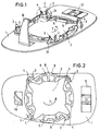
- a first component of the invention in the form a mirror glass carrier consists of a base part 1 and a moving part 2. Along a circular line several pairs of locking hooks 3.4 are provided.
- the locking hooks 3 are fixed to the base part 1, the back of the Mirror glass carrier connected, on the opposite For example, a mirror glass is glued on the side is.
- the locking hooks 3 are also extremely rigid. For this purpose, between the locking hook 3 and the Mirror glass support 1, a stiffening rib 31 is provided.
- movable locking hooks 4 At a fixed distance a (Fig. 3) to the fixed Locking hooks 3 are movable locking hooks 4. How 2 can be seen in particular, are Snap hook 4 not directly with the mirror glass support 1 connected. Rather, the locking hooks 4 are over approaches 20 with the moving part 2, one essentially circular plate firmly and rigidly connected. The circular plate 2 is in turn radial Bridges 5 with the mirror glass support 1 elastic connected. The webs 5 are designed so that they are elastic due to their width and thickness Allow plate 2 to rotate in the direction of arrow c. When the plate 2 is turned in the direction arrow c increases the distance between the fixed locking hook 3 and the movable locking hook 4.
- the mirror glass support 1 has the function the locking connection irrelevant guide 10 and fasteners 11 on.
- Fig. 2 also shows a pointer 8, which is fixed to the Plate 2 is connected.
- the pointer 8 is above the Edge area of the mirror glass support in front.
- the locking hooks 3.4 for example by a servomotor attached to the receiving part 6 concealed so that a fitter cannot see can whether the receiving part 6 correctly in the locking hook pairs 3,4 of the mirror glass support 1 and the plate 2 snaps into place.
- the pointer 8 seen by the fitter it is possible to turn the plate 2 and thus an opening of the locking hook pairs 3, 4 observe. This ensures that as soon as the pointer also moves from its central position over the edge area of the mirror glass carrier 1 approaches 9 above and then back again moved to its starting position, all tabs 7 (Fig. 4) are engaged in the locking hook pairs 3.4.
- this can also be used as a handle part for opening the latching connection can be used by the pointer 8 by means of of an appropriate tool is moved to the right and thus causing the plate 2 to rotate. Consequently can the receiving part 6 (Fig. 4), for example for repair work, easily from the mirror glass support 1 separate.
- Fig. 1 From the enlargement of the Fig. 1 designated Z is the shape of the Locking hooks 3 and 4 can be seen. Both locking hooks 3.4 have Projections 30 and 40 on. For safe shooting an approach 7 (Fig. 4) in the locking hook pair 3.4 To ensure, both locking hooks 3 and 4 of the Projections 30 and 40 in the direction of the Mirror glass carrier 1 tapered end facing away. In the direction of the mirror glass carrier 1 have the projections 30.40 a right-angled approach, so that an in the locking hook pair 3.4 latched approach 7 (Fig. 4) can no longer be pulled up out of the locking hook pair 3, 4 is.
- FIG. 4 shows an example of a top view of a preferred one Embodiment of a component for receiving a servomotor, not shown.
- the second Component in the form of the receiving part 6 is rotationally symmetrical and has lugs 7 on its outer circumference on.
- the outside diameter of the receiving part 6 is somewhat smaller than the diameter of the circle on which the locking hooks 3 and 4 (FIGS. 1 and 2) are located.
- the distances between the lugs 7 the distances between the locking hook pairs 3.4 correspond, the approaches 7 snap together of the first component 1, 2 with the second component 6 into the locking hooks 3.4.
- the receiving part 6 in Fig. 2 only from above with the Plate 2 connected mirror glass carrier 1 placed and be pushed down.
- the receiving part 6 has, for example, for receiving of the adjustment motor mounting holes 61.
Landscapes
- Engineering & Computer Science (AREA)
- Multimedia (AREA)
- Mechanical Engineering (AREA)
- Hooks, Suction Cups, And Attachment By Adhesive Means (AREA)
- Snaps, Bayonet Connections, Set Pins, And Snap Rings (AREA)
- Rear-View Mirror Devices That Are Mounted On The Exterior Of The Vehicle (AREA)
Applications Claiming Priority (4)
| Application Number | Priority Date | Filing Date | Title |
|---|---|---|---|
| DE29618497U | 1996-10-23 | ||
| DE29618497U DE29618497U1 (de) | 1996-10-23 | 1996-10-23 | Rastverbindung |
| DE19732690A DE19732690C2 (de) | 1996-10-23 | 1997-07-30 | Rastverbindung |
| DE19732690 | 1997-07-30 |
Publications (2)
| Publication Number | Publication Date |
|---|---|
| EP0838598A2 true EP0838598A2 (fr) | 1998-04-29 |
| EP0838598A3 EP0838598A3 (fr) | 1999-04-28 |
Family
ID=26038666
Family Applications (1)
| Application Number | Title | Priority Date | Filing Date |
|---|---|---|---|
| EP97117567A Withdrawn EP0838598A3 (fr) | 1996-10-23 | 1997-10-10 | Système d'assemblage par encliquetage |
Country Status (1)
| Country | Link |
|---|---|
| EP (1) | EP0838598A3 (fr) |
Cited By (3)
| Publication number | Priority date | Publication date | Assignee | Title |
|---|---|---|---|---|
| EP1186474A1 (fr) * | 2000-09-08 | 2002-03-13 | Metagal Industria E Comercio Ltda. | Dispositif pour fixer un support de miroir d'un rétroviseur à un mécanisme de réglage |
| WO2007128468A1 (fr) * | 2006-05-05 | 2007-11-15 | Fico Mirrors, S.A. | Dispositif de fixation pour mécanismes de réglage de position destinés à des rétroviseurs extérieurs de véhicules à moteur |
| EP2457770A1 (fr) * | 2010-11-29 | 2012-05-30 | SMR Patents S.à.r.l. | Dispositif d'assemblage et de retenue de verre plastique |
Family Cites Families (9)
| Publication number | Priority date | Publication date | Assignee | Title |
|---|---|---|---|---|
| DE2907433C2 (de) * | 1979-02-26 | 1981-04-23 | Hohe Kg, 6981 Collenberg | Kraftfahrzeug-Außenspiegel mit auswechselbarem Spiegelglas |
| DE3144547A1 (de) * | 1981-11-10 | 1983-05-19 | Wolfgang 7140 Ludwigsburg Zipperle | Verstellbarer spiegel fuer kraftfahrzeuge |
| JPH0630563Y2 (ja) * | 1987-01-13 | 1994-08-17 | 株式会社村上開明堂 | ミラーエレメントの保持装置 |
| US4844645A (en) * | 1988-02-29 | 1989-07-04 | Hewlett-Packard Company | Locking system |
| JPH0628358Y2 (ja) * | 1988-04-11 | 1994-08-03 | 株式会社村上開明堂 | バックミラー |
| DE4138934C1 (en) * | 1991-11-27 | 1993-05-13 | Hohe Kg, 6981 Collenberg, De | External rear view mirror on vehicle - has set of locking elements connected to mirror glass and further elements connected to housing |
| GB9208831D0 (en) * | 1992-04-23 | 1992-06-10 | Britax Wingard Ltd | Exterior rear view mirror for a motor vehicle |
| DE4302950A1 (de) * | 1993-02-03 | 1994-08-04 | Mekra Rangau Plastics | Verstellbare Rückspiegelanordnung für Kraftfahrzeuge |
| US5604645A (en) * | 1995-03-17 | 1997-02-18 | United Technologies Automotive Systems | Mirror motor mounting bracket |
-
1997
- 1997-10-10 EP EP97117567A patent/EP0838598A3/fr not_active Withdrawn
Cited By (8)
| Publication number | Priority date | Publication date | Assignee | Title |
|---|---|---|---|---|
| EP1186474A1 (fr) * | 2000-09-08 | 2002-03-13 | Metagal Industria E Comercio Ltda. | Dispositif pour fixer un support de miroir d'un rétroviseur à un mécanisme de réglage |
| WO2007128468A1 (fr) * | 2006-05-05 | 2007-11-15 | Fico Mirrors, S.A. | Dispositif de fixation pour mécanismes de réglage de position destinés à des rétroviseurs extérieurs de véhicules à moteur |
| US8075146B2 (en) | 2006-05-05 | 2011-12-13 | Fico Mirrors, S.A. | Fixing device for position regulating mechanisms for external rear-view mirrors on motor vehicles |
| CN101437706B (zh) * | 2006-05-05 | 2012-06-13 | 菲科镜子股份公司 | 用于机动车辆上外部后视镜的位置调节机构的固定设备 |
| EP2457770A1 (fr) * | 2010-11-29 | 2012-05-30 | SMR Patents S.à.r.l. | Dispositif d'assemblage et de retenue de verre plastique |
| CN102476608A (zh) * | 2010-11-29 | 2012-05-30 | Smr专利责任有限公司 | 塑料玻璃安装和保持装置 |
| US8579445B2 (en) | 2010-11-29 | 2013-11-12 | Smr Patents S.A.R.L. | Plastic glass mounting and retention device |
| CN102476608B (zh) * | 2010-11-29 | 2014-09-24 | Smr专利责任有限公司 | 塑料玻璃安装和保持装置 |
Also Published As
| Publication number | Publication date |
|---|---|
| EP0838598A3 (fr) | 1999-04-28 |
Similar Documents
| Publication | Publication Date | Title |
|---|---|---|
| EP0582095B1 (fr) | Dispositif de fixation en matière plastique | |
| DE4233239C2 (de) | Kraftbetriebenes Werkzeug mit einer Hakenvorrichtung | |
| DE2734312C2 (fr) | ||
| DE60304318T2 (de) | Befestigung einer rohrklemme | |
| DE3404800C2 (fr) | ||
| DE69804149T2 (de) | Verriegelungshebelmechanismus für Verbinder | |
| EP0232917B1 (fr) | Procédé et accouplement et fixation pour le montage des affichages d'image | |
| DE3402890C2 (de) | Hebelanordnung für Kraftfahrzeugtüren od. dgl. | |
| WO2000068582A1 (fr) | Element d'assemblage | |
| DE68902278T2 (de) | Befestigung eines buendels von laenglichen gegenstaenden oder eines nichtkreisfoermigen laenglichen gegenstandes auf einer unterlage. | |
| DE69622128T2 (de) | Vorrichtung zur Befestigung eines Elementes, insbesondere eines Rohres, an einer Wand | |
| DE60123349T2 (de) | Befestigungsvorrichtung | |
| DE2056723B2 (de) | Befestigungsvorrichtung an einem Türschild mit Handhabenlagerungsbohrang | |
| EP0754827A2 (fr) | Dispositif pour la fixation amovible et axialement non coulissante d'une poignée sur un élément de palier, notamment pour une poignée de porte ou fenêtre | |
| EP0838598A2 (fr) | Système d'assemblage par encliquetage | |
| DE19732690C2 (de) | Rastverbindung | |
| DE3735912A1 (de) | Nachgiebig befestigter veraenderbarer widerstand | |
| DE4427723C2 (de) | Zweiteiliges Befestigungssystem | |
| EP0837252B1 (fr) | Elément de fixation | |
| DE3244516A1 (de) | Vorrichtung zur loesbaren verbindung des geraetetraegers mit der schiene einer leuchte, z. b. fuer leuchtstofflampen | |
| DE29714671U1 (de) | Lochscheibe | |
| DE69803638T2 (de) | Kupplungssteuerungsvorrichtung | |
| EP0063294B1 (fr) | Dispositif de fixation, en particulier pour accoudoir ou poignées à la paroi intérieure de carosserie pour véhicules | |
| DE60005236T2 (de) | Befestigungssystem | |
| EP1382861B1 (fr) | Dispositif pour verrouiller deux éléments constructifs ensemble |
Legal Events
| Date | Code | Title | Description |
|---|---|---|---|
| PUAI | Public reference made under article 153(3) epc to a published international application that has entered the european phase |
Free format text: ORIGINAL CODE: 0009012 |
|
| AK | Designated contracting states |
Kind code of ref document: A2 Designated state(s): DE ES FR GB IT NL SE |
|
| AX | Request for extension of the european patent |
Free format text: AL;LT;LV;RO;SI |
|
| PUAL | Search report despatched |
Free format text: ORIGINAL CODE: 0009013 |
|
| AK | Designated contracting states |
Kind code of ref document: A3 Designated state(s): AT BE CH DE DK ES FI FR GB GR IE IT LI LU MC NL PT SE |
|
| AX | Request for extension of the european patent |
Free format text: AL;LT;LV;RO;SI |
|
| 17P | Request for examination filed |
Effective date: 19991007 |
|
| AKX | Designation fees paid |
Free format text: DE ES FR GB IT NL SE |
|
| GRAG | Despatch of communication of intention to grant |
Free format text: ORIGINAL CODE: EPIDOS AGRA |
|
| 17Q | First examination report despatched |
Effective date: 20001122 |
|
| GRAG | Despatch of communication of intention to grant |
Free format text: ORIGINAL CODE: EPIDOS AGRA |
|
| GRAH | Despatch of communication of intention to grant a patent |
Free format text: ORIGINAL CODE: EPIDOS IGRA |
|
| STAA | Information on the status of an ep patent application or granted ep patent |
Free format text: STATUS: THE APPLICATION IS DEEMED TO BE WITHDRAWN |
|
| 18D | Application deemed to be withdrawn |
Effective date: 20010713 |