EP0838828B1 - Dispositif de commande par interrupteurs et citerne le mettant en oeuvre - Google Patents
Dispositif de commande par interrupteurs et citerne le mettant en oeuvre Download PDFInfo
- Publication number
- EP0838828B1 EP0838828B1 EP96402244A EP96402244A EP0838828B1 EP 0838828 B1 EP0838828 B1 EP 0838828B1 EP 96402244 A EP96402244 A EP 96402244A EP 96402244 A EP96402244 A EP 96402244A EP 0838828 B1 EP0838828 B1 EP 0838828B1
- Authority
- EP
- European Patent Office
- Prior art keywords
- switches
- tank
- switch
- detector
- circuit
- Prior art date
- Legal status (The legal status is an assumption and is not a legal conclusion. Google has not performed a legal analysis and makes no representation as to the accuracy of the status listed.)
- Expired - Lifetime
Links
Images


Classifications
-
- H—ELECTRICITY
- H01—ELECTRIC ELEMENTS
- H01H—ELECTRIC SWITCHES; RELAYS; SELECTORS; EMERGENCY PROTECTIVE DEVICES
- H01H36/00—Switches actuated by change of magnetic field or of electric field, e.g. by change of relative position of magnet and switch, by shielding
- H01H36/0006—Permanent magnet actuating reed switches
- H01H36/006—Permanent magnet actuating reed switches comprising a plurality of reed switches, e.g. selectors or joystick-operated
-
- H—ELECTRICITY
- H01—ELECTRIC ELEMENTS
- H01H—ELECTRIC SWITCHES; RELAYS; SELECTORS; EMERGENCY PROTECTIVE DEVICES
- H01H25/00—Switches with compound movement of handle or other operating part
- H01H25/002—Switches with compound movement of handle or other operating part having an operating member rectilinearly slidable in different directions
Definitions
- the invention relates to a control device which is simple to manufacture, does not not requiring a waterproof, explosion-proof and ensuring auxiliary power source that the switches are well operated, even if the person carrying out the maneuver is pressed.
- control device according to the invention is defined in the claim 1.
- the operating member is a magnet and the switches are soft-blade switches called a reed blade.
- the invention also relates to a tank comprising an appearance detector of water which cooperates with an electrical information circuit with a switch, a switch intended to prevent a current source supplying the circuit electric flow after the detector has detected an appearance of water, and a means with switch for checking the correct functioning of the information circuit, the switches being integrated in a control device according to the invention.
- the control device shown in Figures 1 and 2 includes four switches 1, 2, 3, 4 with flexible blades arranged facing one face of a guide piece 5 comprising a slide 6 in staircase with four steps at 90 °. Each end of a step is facing a switch.
- a card 7 provided with a magnet 8 forming operating device.
- the operating member 8 When the operating member 8 arrives, the card 7 being inserted in room 5, at the non-free end of the first lap, it is opposite switch 4 and, to climb the staircase formed by the slide, the operator must change direction so that, before the change of direction, the magnet 8 is stationary and can act well on switch 4.
- the slide 6 is sawtooth making an angle of 45 °.
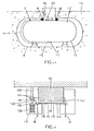
- the tank shown in Figure 4 is designated as a whole by the reference 11. It comprises a tank 12 surrounded by an envelope 13 which defines with the outer surface 14 of the tank 12 a sealed enclosure 15 of which sealing is provided by seals 16. An entry (no shown), fitted with a plug allows the introduction of anhydrous gas or fluid in enclosure 15.
- a detector 17 of the appearance of water connected by conductors 18,19 to an information means 110 making it possible to find out if the detector 17 has detected condensation.
- This means of information 110 is easily accessible to the user of the tank by being close to the surface of the sol S.
- the detector ( Figure 5) consists of an insulating membrane 111 electrically and thermally conductive, for example SILPAD 400 manufactured by the company BERGQUIST, one side of which is in permanent contact with the external surface 14 of the tank by means of a magnet 112, conductor of the heat, while the other face 113 is covered with a layer 114 of salt hygroscopic (LiCl, NaCl, or the like), the conductivity of which in solution is much larger than in crystallized form.
- two electrodes 115, 116 made of a stainless material (gold, platinum or the like), arranged in intimate contact with the face 113 of the membrane 111.
- a housing 117 plastic covers the inside of the detector enclosure to protect the layer of hygroscopic salt and can serve as a reserve of hygroscopic salt.
- a switch 118 with spring has its spring 138 mounted compressed between the bottom of the housing 117 forming a stop and the outer surface 14 of the tank with interposition of a pusher 139 provided with a pallet 140.
- the spring 138 relaxes because the bottom 117 moves away from the surface 14, the conductive paddle 140 comes into contact with two terminals 141, and is connected by two conductors 119,120 to each of the electrodes.
- Two conductors 18,19 connect the electrodes by means 110 of information after having passed through the sealed envelope 13 through orifices waterproof.
- This information means 110 includes an electrical circuit 121 connected to the terminals of the conductors 18,19 from the electrodes.
- the conductor 18 is connected to the base of a transistor 122, of which the transmitter is connected to a first branch 123a of a bistable relay 123 with two NF and NO positions.
- This bistable relay branch 123a is connected by a wire electrical on the one hand to a terminal of an electric current source 124 and on the other goes to the second branch of the bistable relay 123b with two positions NC and NO.
- This the latter is connected by an electric wire to a lamp 125, serving as a means of detection of current flow, itself connected to a manual switch 126 itself connected to the collector of transistor 122.
- the second source terminal of electric current 124 is also connected to the collector of transistor 122.
- a branch comprising a reset switch 127 and a coil 128 auxiliary is mounted between the electric current source terminal which is also connected to the bistable relay 123.
- the coil 129 is part of the bistable relay 123.
- Two other conductors 130, 131 are mounted on the terminals of the electrodes 115, 116 and connected, after having passed through the casing 13 in a sealed manner, by a check switch 132.
- the liquid or gas to be stored in the tank of the tank for example a liquefied petroleum gas and a gas or a fluid anhydrous in the sealed enclosure 15.
- the tightness of the enclosure 15 makes it possible to ensure that the outer surface 14 of the tank 12 is never subjected to a humid atmosphere, which protects it against corrosion. If nevertheless moisture manages to enter enclosure 15, it will ensue, due to the low temperature of liquefied petroleum gases in the lower part from the inside of the tank, that condensation water appears on the surface outside of the tank, and in particular in the bottom of the tank where the temperature is the lowest.
- This appearance of water is detected by the appearance detector 17 of water. Via conductors 18,19, information that water has been detected is transmitted to the lamp 125 which lets the user know that a intervention is necessary to prevent future corrosion of the tank 12.
- Switch 132 bypasses the electrodes and allows the current to pass between them. By closing it, the user can then verify that the means 110 information works normally, if the lamp comes on. If it does not light up not, it is that a defect exists in the information medium 110 (defective cable, defective components, etc.) and intervention is required.
- the user reopens the switch 126 manual and briefly closes the reset switch 127 which resets the bistable relay to its normal position by supplying the coil 129 relay auxiliary.
- the switch 126 and to the branch 123a Thanks to the switch 126 and to the branch 123a, the current source electric does not deliver during the whole time between the moment when water appeared and the moment when the user proceeds to his operations. This therefore allows ensure a very long battery life.
- a resistor 136 is mounted between the electrodes (115,116) in hygroscopic salt 114 inside a sheath 137 in one material highly absorbent of water and with low desorption.
Landscapes
- Push-Button Switches (AREA)
- Electrical Discharge Machining, Electrochemical Machining, And Combined Machining (AREA)
- Investigating Or Analyzing Materials By The Use Of Electric Means (AREA)
- Use Of Switch Circuits For Exchanges And Methods Of Control Of Multiplex Exchanges (AREA)
- Switches That Are Operated By Magnetic Or Electric Fields (AREA)
Description
- si la lampe s'allume, que du courant est passé entre les électrodes depuis la dernière fois que le relais bistable 123 se trouvait dans sa position normale (branche A fermée, branche B ouverte), (en général la dernière visite) ;
- si la lampe ne s'allume pas et s'allume lorsqu'il ferme l'interrupteur 132 de vérification qu'aucun courant n'a circulé depuis la dernière fois que le relais bistable a été mis en position normale.
Claims (5)
- Dispositif de commande comprenant au moins 3 interrupteurs (1, 2, 3, 4) et un organe de manoeuvre (8) commun à ces interrupteurs (1, 2, 3, 4) guidé dans une coulisse (6) dont quatre tronçons successifs font, deux à deux, un angle entre eux, les interrupteurs étant prévus en regard des sommets des angles formés par ces tronçons, caractérisé en ce que lesdits angles sont inférieurs à 120° et, de préférence, inférieur ou égal à 90°.
- Dispositif suivant la revendication 1, caractérisé en ce que l'organe de manoeuvre (8) est un aimant et les interrupteurs sont des interrupteurs à lame souple.
- Dispositif suivant la revendication 1 ou 2, caractérisé en ce que la coulisse est en dents de scie.
- Citerne comportantun détecteur (17) d'apparition d'eau qui coopère avec un circuit électrique d'information (110) à interrupteur (118),un interrupteur (23a) destiné à empêcher une source de courant alimentant le circuit électrique de débiter après que le détecteur (17) a détecté une apparition d'eau,un interrupteur (132) de vérification du bon fonctionnement du circuit d'information (110), etles interrupteurs (118,123a et 132) sont intégrés dans un dispositif de commande suivant l'une des revendications précédentes.
- L'utilisation d'un dispositif suivant l'une des revendications 1 à 3, dans une citerne.
Priority Applications (4)
| Application Number | Priority Date | Filing Date | Title |
|---|---|---|---|
| DE69608803T DE69608803T2 (de) | 1996-10-22 | 1996-10-22 | Steuervorrichtung durch Schalter und damit versehenen Tank |
| AT96402244T ATE193786T1 (de) | 1996-10-22 | 1996-10-22 | Steuervorrichtung durch schalter und damit versehenen tank |
| ES96402244T ES2146370T3 (es) | 1996-10-22 | 1996-10-22 | Dispositivo de mando por interruptores y cisterna que lo utiliza. |
| EP96402244A EP0838828B1 (fr) | 1996-10-22 | 1996-10-22 | Dispositif de commande par interrupteurs et citerne le mettant en oeuvre |
Applications Claiming Priority (1)
| Application Number | Priority Date | Filing Date | Title |
|---|---|---|---|
| EP96402244A EP0838828B1 (fr) | 1996-10-22 | 1996-10-22 | Dispositif de commande par interrupteurs et citerne le mettant en oeuvre |
Publications (2)
| Publication Number | Publication Date |
|---|---|
| EP0838828A1 EP0838828A1 (fr) | 1998-04-29 |
| EP0838828B1 true EP0838828B1 (fr) | 2000-06-07 |
Family
ID=8225303
Family Applications (1)
| Application Number | Title | Priority Date | Filing Date |
|---|---|---|---|
| EP96402244A Expired - Lifetime EP0838828B1 (fr) | 1996-10-22 | 1996-10-22 | Dispositif de commande par interrupteurs et citerne le mettant en oeuvre |
Country Status (4)
| Country | Link |
|---|---|
| EP (1) | EP0838828B1 (fr) |
| AT (1) | ATE193786T1 (fr) |
| DE (1) | DE69608803T2 (fr) |
| ES (1) | ES2146370T3 (fr) |
Family Cites Families (2)
| Publication number | Priority date | Publication date | Assignee | Title |
|---|---|---|---|---|
| GB2128027B (en) * | 1982-10-01 | 1985-11-06 | Electronic Components Ltd | Gearbox indicator switch |
| DE4392581D2 (de) * | 1992-06-09 | 1995-04-27 | Bistekos Michael Georg | Einrichtung zur programmierbaren Steuerung von elektrischen bzw. elektronischen Geräten |
-
1996
- 1996-10-22 AT AT96402244T patent/ATE193786T1/de not_active IP Right Cessation
- 1996-10-22 ES ES96402244T patent/ES2146370T3/es not_active Expired - Lifetime
- 1996-10-22 DE DE69608803T patent/DE69608803T2/de not_active Expired - Fee Related
- 1996-10-22 EP EP96402244A patent/EP0838828B1/fr not_active Expired - Lifetime
Also Published As
| Publication number | Publication date |
|---|---|
| ES2146370T3 (es) | 2000-08-01 |
| ATE193786T1 (de) | 2000-06-15 |
| DE69608803T2 (de) | 2001-01-11 |
| EP0838828A1 (fr) | 1998-04-29 |
| DE69608803D1 (de) | 2000-07-13 |
Similar Documents
| Publication | Publication Date | Title |
|---|---|---|
| EP0757008B1 (fr) | Citerne à détecteur | |
| EP0645626B1 (fr) | Dispositif de mesure pour capteurs amovibles | |
| EP0115982B1 (fr) | Dispositif électronique de sécurité pour fer à repasser électrique | |
| FR2509050A1 (fr) | Procede de protection des electrodes detectrices d'une cellule electrochimique a electrolyte solide | |
| WO2007020731A1 (fr) | Sonde de gaz d'hydrogène | |
| FR2573202A1 (fr) | Appareil de mesure pour integrer le temps de fonctionnement d'un separateur d'eau | |
| EP0838828B1 (fr) | Dispositif de commande par interrupteurs et citerne le mettant en oeuvre | |
| FR2471765A1 (fr) | Aspirateur comportant un dispositif protecteur pour l'operateur et procede pour sa fabrication | |
| FR2670985A1 (fr) | Planche de cablage imprime, carte de circuit imprime et appareil electronique. | |
| FR2702880A1 (fr) | Appareil interrupteur électromagnétique. | |
| EP1521080A1 (fr) | Capteur optique d'hydrogène et système | |
| FR3075392A1 (fr) | Surveillance d'un defaut dans un equipement electrique | |
| EP0831510A1 (fr) | Dispositif de déclenchement thermique pour appareil de protection | |
| CA1299623C (fr) | Element electrique isole chauffant a dispositif de securite detectant la defaillance de l'isolement electrique | |
| FR2750765A1 (fr) | Detecteur de liquide dans un element d'une installation et son utilisation pour la detection de fuites | |
| FR2520107A1 (fr) | Sonde de determination du niveau de gaz liquides | |
| FR2728546A1 (fr) | Procede de controle du bon etat de la cuve d'une citerne | |
| FR2825512A1 (fr) | Indicateur de l'etat d'un fusible actionne magnetiquement | |
| EP1203226B1 (fr) | Detecteur de gaz | |
| FR2645274A1 (fr) | Dispositif detecteur d'humidite et de presence d'eau | |
| EP0845843A1 (fr) | Dispositif de protection pour lignes téléphoniques | |
| FR2461252A1 (fr) | Detecteur d'oxygene a electrolyte solide et procede de fabrication du detecteur | |
| FR2584459A1 (fr) | Dispositif de commande d'une electropompe, submersible et immergee dans une cuve ou similaire contenant un liquide, en fonction du niveau du liquide dans cette cuve et electropompe equipee de ce dispositif | |
| FR2894054A1 (fr) | Thermostat et systeme embarque de detection de surchauffe. | |
| FR2645958A1 (fr) | Thermocouple etanche pour dispositif de securite electromagnetique notamment pour chaudieres ou chauffe-bains a gaz |
Legal Events
| Date | Code | Title | Description |
|---|---|---|---|
| PUAI | Public reference made under article 153(3) epc to a published international application that has entered the european phase |
Free format text: ORIGINAL CODE: 0009012 |
|
| AK | Designated contracting states |
Kind code of ref document: A1 Designated state(s): AT BE DE DK ES FR GB GR IT LU NL |
|
| 17P | Request for examination filed |
Effective date: 19980512 |
|
| AKX | Designation fees paid |
Free format text: AT BE DE DK ES FR GB GR IT LU NL |
|
| RBV | Designated contracting states (corrected) |
Designated state(s): AT BE DE DK ES FR GB GR IT LU NL |
|
| GRAG | Despatch of communication of intention to grant |
Free format text: ORIGINAL CODE: EPIDOS AGRA |
|
| GRAG | Despatch of communication of intention to grant |
Free format text: ORIGINAL CODE: EPIDOS AGRA |
|
| GRAH | Despatch of communication of intention to grant a patent |
Free format text: ORIGINAL CODE: EPIDOS IGRA |
|
| 17Q | First examination report despatched |
Effective date: 19991115 |
|
| GRAH | Despatch of communication of intention to grant a patent |
Free format text: ORIGINAL CODE: EPIDOS IGRA |
|
| GRAA | (expected) grant |
Free format text: ORIGINAL CODE: 0009210 |
|
| AK | Designated contracting states |
Kind code of ref document: B1 Designated state(s): AT BE DE DK ES FR GB GR IT LU NL |
|
| PG25 | Lapsed in a contracting state [announced via postgrant information from national office to epo] |
Ref country code: NL Free format text: LAPSE BECAUSE OF FAILURE TO SUBMIT A TRANSLATION OF THE DESCRIPTION OR TO PAY THE FEE WITHIN THE PRESCRIBED TIME-LIMIT Effective date: 20000607 Ref country code: GR Free format text: LAPSE BECAUSE OF NON-PAYMENT OF DUE FEES Effective date: 20000607 Ref country code: GB Free format text: LAPSE BECAUSE OF FAILURE TO SUBMIT A TRANSLATION OF THE DESCRIPTION OR TO PAY THE FEE WITHIN THE PRESCRIBED TIME-LIMIT Effective date: 20000607 |
|
| REF | Corresponds to: |
Ref document number: 193786 Country of ref document: AT Date of ref document: 20000615 Kind code of ref document: T |
|
| ITF | It: translation for a ep patent filed | ||
| REF | Corresponds to: |
Ref document number: 69608803 Country of ref document: DE Date of ref document: 20000713 |
|
| REG | Reference to a national code |
Ref country code: ES Ref legal event code: FG2A Ref document number: 2146370 Country of ref document: ES Kind code of ref document: T3 |
|
| PG25 | Lapsed in a contracting state [announced via postgrant information from national office to epo] |
Ref country code: DK Free format text: LAPSE BECAUSE OF FAILURE TO SUBMIT A TRANSLATION OF THE DESCRIPTION OR TO PAY THE FEE WITHIN THE PRESCRIBED TIME-LIMIT Effective date: 20000907 |
|
| PG25 | Lapsed in a contracting state [announced via postgrant information from national office to epo] |
Ref country code: LU Free format text: LAPSE BECAUSE OF NON-PAYMENT OF DUE FEES Effective date: 20001022 |
|
| PGFP | Annual fee paid to national office [announced via postgrant information from national office to epo] |
Ref country code: AT Payment date: 20001031 Year of fee payment: 5 |
|
| NLV1 | Nl: lapsed or annulled due to failure to fulfill the requirements of art. 29p and 29m of the patents act | ||
| GBV | Gb: ep patent (uk) treated as always having been void in accordance with gb section 77(7)/1977 [no translation filed] |
Effective date: 20000607 |
|
| PLBE | No opposition filed within time limit |
Free format text: ORIGINAL CODE: 0009261 |
|
| STAA | Information on the status of an ep patent application or granted ep patent |
Free format text: STATUS: NO OPPOSITION FILED WITHIN TIME LIMIT |
|
| 26N | No opposition filed | ||
| PGFP | Annual fee paid to national office [announced via postgrant information from national office to epo] |
Ref country code: DE Payment date: 20011004 Year of fee payment: 6 |
|
| PG25 | Lapsed in a contracting state [announced via postgrant information from national office to epo] |
Ref country code: AT Free format text: LAPSE BECAUSE OF NON-PAYMENT OF DUE FEES Effective date: 20011022 |
|
| PG25 | Lapsed in a contracting state [announced via postgrant information from national office to epo] |
Ref country code: DE Free format text: LAPSE BECAUSE OF NON-PAYMENT OF DUE FEES Effective date: 20030501 |
|
| PGFP | Annual fee paid to national office [announced via postgrant information from national office to epo] |
Ref country code: IT Payment date: 20071025 Year of fee payment: 12 |
|
| PG25 | Lapsed in a contracting state [announced via postgrant information from national office to epo] |
Ref country code: IT Free format text: LAPSE BECAUSE OF NON-PAYMENT OF DUE FEES Effective date: 20081022 |
|
| PGFP | Annual fee paid to national office [announced via postgrant information from national office to epo] |
Ref country code: FR Payment date: 20120905 Year of fee payment: 17 |
|
| PGFP | Annual fee paid to national office [announced via postgrant information from national office to epo] |
Ref country code: BE Payment date: 20121025 Year of fee payment: 17 |
|
| PGFP | Annual fee paid to national office [announced via postgrant information from national office to epo] |
Ref country code: ES Payment date: 20121022 Year of fee payment: 17 |
|
| BERE | Be: lapsed |
Owner name: SOCIETE METALLURGIQUE *LIOTARD FRERES S.A. Effective date: 20131031 |
|
| REG | Reference to a national code |
Ref country code: FR Ref legal event code: ST Effective date: 20140630 |
|
| PG25 | Lapsed in a contracting state [announced via postgrant information from national office to epo] |
Ref country code: FR Free format text: LAPSE BECAUSE OF NON-PAYMENT OF DUE FEES Effective date: 20131031 |
|
| PG25 | Lapsed in a contracting state [announced via postgrant information from national office to epo] |
Ref country code: BE Free format text: LAPSE BECAUSE OF NON-PAYMENT OF DUE FEES Effective date: 20131031 |
|
| REG | Reference to a national code |
Ref country code: ES Ref legal event code: FD2A Effective date: 20141107 |
|
| PG25 | Lapsed in a contracting state [announced via postgrant information from national office to epo] |
Ref country code: ES Free format text: LAPSE BECAUSE OF NON-PAYMENT OF DUE FEES Effective date: 20131023 |