EP0838913A2 - Stabilisierte Leistungsregelung für optische Übertragungssysteme - Google Patents
Stabilisierte Leistungsregelung für optische Übertragungssysteme Download PDFInfo
- Publication number
- EP0838913A2 EP0838913A2 EP97307814A EP97307814A EP0838913A2 EP 0838913 A2 EP0838913 A2 EP 0838913A2 EP 97307814 A EP97307814 A EP 97307814A EP 97307814 A EP97307814 A EP 97307814A EP 0838913 A2 EP0838913 A2 EP 0838913A2
- Authority
- EP
- European Patent Office
- Prior art keywords
- optical
- power
- change
- damping
- signal
- Prior art date
- Legal status (The legal status is an assumption and is not a legal conclusion. Google has not performed a legal analysis and makes no representation as to the accuracy of the status listed.)
- Granted
Links
Images




Classifications
-
- H—ELECTRICITY
- H04—ELECTRIC COMMUNICATION TECHNIQUE
- H04B—TRANSMISSION
- H04B10/00—Transmission systems employing electromagnetic waves other than radio-waves, e.g. infrared, visible or ultraviolet light, or employing corpuscular radiation, e.g. quantum communication
- H04B10/50—Transmitters
- H04B10/501—Structural aspects
- H04B10/503—Laser transmitters
- H04B10/505—Laser transmitters using external modulation
-
- H—ELECTRICITY
- H04—ELECTRIC COMMUNICATION TECHNIQUE
- H04B—TRANSMISSION
- H04B10/00—Transmission systems employing electromagnetic waves other than radio-waves, e.g. infrared, visible or ultraviolet light, or employing corpuscular radiation, e.g. quantum communication
- H04B10/50—Transmitters
- H04B10/501—Structural aspects
- H04B10/503—Laser transmitters
-
- H—ELECTRICITY
- H04—ELECTRIC COMMUNICATION TECHNIQUE
- H04B—TRANSMISSION
- H04B10/00—Transmission systems employing electromagnetic waves other than radio-waves, e.g. infrared, visible or ultraviolet light, or employing corpuscular radiation, e.g. quantum communication
- H04B10/50—Transmitters
- H04B10/501—Structural aspects
- H04B10/506—Multiwavelength transmitters
-
- H—ELECTRICITY
- H04—ELECTRIC COMMUNICATION TECHNIQUE
- H04B—TRANSMISSION
- H04B10/00—Transmission systems employing electromagnetic waves other than radio-waves, e.g. infrared, visible or ultraviolet light, or employing corpuscular radiation, e.g. quantum communication
- H04B10/50—Transmitters
- H04B10/564—Power control
-
- H—ELECTRICITY
- H04—ELECTRIC COMMUNICATION TECHNIQUE
- H04J—MULTIPLEX COMMUNICATION
- H04J14/00—Optical multiplex systems
- H04J14/02—Wavelength-division multiplex systems
- H04J14/0221—Power control, e.g. to keep the total optical power constant
- H04J14/02212—Power control, e.g. to keep the total optical power constant by addition of a dummy signal
Definitions
- the present invention relates to methods of operating optical transmission systems, to methods of controlling transmitters, to methods of controlling an optical power damping element, to optical transmission systems, to transmitters, and to damping systems.
- the power level of an optical signal in an optical transmission system limits the distance between regenerators or amplifiers, and needs to be controlled carefully to avoid errors in the detected bits.
- a signal with too high an optical power is subject to nonlinear effects in the fibre such as Self-Phase-Modulation that can seriously degrade the signal. This causes bit errors or loss of frame in the signal. These nonlinear effects are especially severe at bit rates at and above 10 Gb/s.
- the onset of the nonlinear degradations can be quite sharp, in that only one or two dB of increase in power level can push a signal from optimum performance to a failed state.
- a signal with too low an optical power is subject to noise degradations after attenuation by the optical link.
- Erbium Doped Fibre Amplifiers can cause amplitude transients when amplifying several wavelengths at once.
- the output power at the other wavelength will increase by 3 dB.
- the speed of this transient is determined by the pump power and by the response of the erbium doped fibre, and is measured in microseconds.
- Addition of a second wavelength causes a similar 3 dB drop in the output power of the first wavelength present.
- Wavelengths In a wavelength division multiplex system new wavelengths commonly need to be added to systems that are in service. This may be due to an upgrade or may be caused by replacing a unit. Wavelengths also need to be removed when replacing a unit or reconfiguring the system.
- Rapid changes in the power of an optical signal at one wavelength can move another signal away from its optimum power level towards too high or too low a power.
- Power margin must be allocated in the design of the optical system so that during a worst case transient, when combined with other worst case conditions, the data remains error free.
- Allowing this margin reduces the available performance of the system, for example, reducing the maximum allowed amplifier spacings.
- amplitude transients can cause phase transients in clock recovery circuits that can exceed allowable jitter ranges, even to the extent of causing bit errors.
- a method of operating an optical transmission system comprising the steps of: transmitting at least one optical signal to an optical element which is sensitive to changes in the optical power of the signal; determining that the optical power is going to change; and damping the change in the signal input to the element, in response to the determination.
- an instruction to change the power level is intercepted. This enables the instructed change to take place gradually, to reduce the disturbance which may be caused by the change.
- the determination of change is carried out by measuring the optical power, and extrapolating from the measurement. This enables unforeseen changes to be damped before they cause disturbances.
- the optical signal comprises a plurality of wavelengths and the damping step involves damping of one or more wavelengths individually.
- the damping step involves damping of one or more wavelengths individually.
- the total power to be maintained without disturbing changes.
- optical amplifiers are sensitive to changes in total power.
- a power change in one wavelength band is determined, and the damping step comprises the step of damping the change in total power by applying a gradually reducing compensating change to the power level of at least one other of the wavelength bands.
- the compensating change which may be rapid, can be divided across a number of wavelengths, or that a dummy wavelength band can be used purely for the purpose of maintaining a stable overall power.
- the damping step involves controlling the output power of an optical source of the optical signal. This means existing control circuitry can be used with little modification.
- the method further comprises the step of controlling an output power of the optical source using a control loop with a predetermined maximum rate of change, wherein in the damping step is carried out with a lower rate of change.
- the optical element is an optical amplifier and the method further comprises the step of controlling the amplifier power output in response to the power in a subset of the wavelength bands. This enables the power margins to be reduced further.
- the method comprises the step of determining a desired rate of damping, according to the amount of change and a desired time to complete the change. This enables the rate of damping to be controlled to suit the circumstances.
- the damping step comprises the step of controlling the power level of a stabilising optical signal, to compensate for the change.
- a method of controlling a transmitter of an optical transmission system comprising the steps of: determining when an instruction to change an output power of the transmitter has been received; and changing the output power according to the instruction, at a rate slower than a usual response rate of the transmitter. This enables undesirable rapid changes to the damped.
- a method of controlling an optical power damping element in an optical transmission system comprising the steps of: determining when there is an optical power change at the input to the element; and damping the change by allowing the output of the element to make a corresponding change, but at a slower rate. This enables rapid changes in power already transmitted, to be damped.
- an optical transmission system comprising: means for transmitting an optical signal; an optical element which is sensitive to changes in the optical power of the signal; means for determining that the optical power is going to change; and means for damping the change in the signal input to the element, responsive to the means for determining the change.
- a transmitter for an optical transmission system comprising: means for determining when an instruction to change an output power of the transmitter has been received; means for converting the instruction to an instruction to change the output power of the transmitter at a rate slower than a usual response rate of the transmitter.
- a damping system for an optical transmission system comprising: means for determining an optical power change at the input to a controllable element; and means for controlling an output of the element to allow a corresponding change at the output, but at a slower rate.
- a method of operating a multiplexed optical transmission system for transmitting a plurality of optical signals, and comprising an element sensitive to changes in optical power comprising the steps of introducing a stabilising signal into the optical path upstream of the element; and controlling the power of the stabilising signal to compensate for changes in power levels of at least some of the other signals transmitted.
- This can be carried out with or without damping, and can enable a reduction in transients and a constant overall power to be achieved.
- the stabilising signal is used to carry information. This improves the overall bandwidth over the case where the stabilising signal is a dummy.
- Such information is carried at a lower rate, which may allow the receiver to cope with greater power transients.
- the information may be carried at a lower rate, or with greater redundancy, to enable improved error handling.
- Figure 1 shows an optical transmission system including optical sources 1, 2, a wavelength division multiplexer 3, and an optical amplifier 4.
- the optical amplifier would be needed at a distance of tens or hundreds of kilometres down the link, to overcome the attenuation caused by optical fibre making up the optical path.
- Numerous amplifiers may be incorporated, according to the distance covered by the transmission system, between the source 1,2 and a receiver (not shown).
- the invention can be applied to systems using a single wavelength band, or using other types of multiplexing such as polarisation multiplexing or time division multiplexing.
- Figure 1 also illustrates a power set point control means 5, provided for each of the optical sources (normally lasers).
- a fade-in/fade-out control means 6 is illustrated, feeding the power set point control means.
- the fade-in/fade-out control means is operable in response to a power level change determining means 7.
- the functions of the set point control 5, the control means 6 and the determining means 7 may be carried out within a conventional micro controller.
- the fade-in/fade-out control means may be operable to gradually vary the set point for the output power of one of the optical sources, according to an external stimulus.
- This external stimulus may take the form of an instruction to switch off one of the optical sources, eg for maintenance or reconfiguration.
- a sudden switch off might produce sufficient change in the total optical power, to disturb the optical amplifier, and cause bit errors.
- the micro controller controlling either or both of the optical sources would gradually reduce the set point for the output power of the appropriate optical source.
- the stimulus for a change could also come from other sources, such as alarm signals indicating that a particular optical source may be at some risk of failing.
- the stimulus could also come from detectors which indicate that maintenance personnel are beginning to extract a card containing an optical source, for maintenance or replacement.
- the rate of change of the power set point it might be appropriate for the rate of change of the power set point to be relatively rapid, for example one or two seconds, to ensure that the fade out is complete before the optical source fails, or is disconnected.
- the fade-out could be extended over the course of around 60 seconds, to allow automatic gain control circuits to adjust the pump power of the optical amplifier for example, and thus minimise the likelihood of bit errors.
- a gradual fade in of the set point of the output power can be initiated in a corresponding way. For example, when it is detected that the optical source has been re-connected, or when alarms have switched off, or when an instruction to add a wavelength is given.
- Transmitters 21 and 22 include power control functions.
- the optical output of the transmitters are passed to attenuators 23, 24 before being passed to a wavelength division multiplexing function 25.
- a total power controller 27 is fed by the optical tap 26.
- the total power controller controls the attenuators 23, 24, and/or the individual output power controllers for the transmitters 21, 22.
- the total power controller, and the individual transmitter power controls may be implemented using a conventional micro controller.
- the attenuators 23, 24 may act as damping elements, to damp any change in output power. Accordingly, prior to switch on of a transmitter, an attenuator could be controlled to pass virtually nothing.
- the attenuator After switch on of the transmitter, the attenuator could be gradually controlled so as to allow a gradual increase in signal output power.
- the attenuator 23 could be controlled so as to gradually reduce the output signal power.
- compensation for transmitter 21 having its power level changed could be carried out by controlling the attenuator 24, associated with a different wavelength.
- attenuator 24 could be controlled so as to reduce the power output of the signal originated from the other transmitter, transmitter 22.
- the compensation is carried out using one or more of the wavelength bands as a stabilising signal.
- attenuators it is not essential to use attenuators to control the power of the stabilising signal.
- the output power of the laser could be controlled as will be described below.
- FIG. 3 shows in schematic form the principal hardware elements involved in controlling the output power of a laser.
- a laser 31 feeds an external modulator 32, whose output is fed via a optical tap 33.
- a small proportion of the optical signal is fed back via an optical to electrical conversion stage 34 (usually a P.I.N. diode).
- Amplification usually follows, before a A to D converter 35 which feeds the micro controller 36.
- This provides the micro controller with values corresponding to the output power of the laser.
- the power values may be updated at a rate of tens of kHz, or hundreds of kHz.
- the micro controller operating at a clock rate of several MHz, or tens of MHz can carry out control algorithms to adjust the output power of the laser, by controlling its bias current.
- a digital to analogue converter 37 converts the output of the micro controller into analogue form, for amplification by an amplifier 38.
- the micro controller 36 may have other inputs, to received instructions from another overall controller, controlling a number of lasers, for example operating at different wavelengths, feeding a multiplexing device in a W.D.M (Wavelength Division Multiplex) system.
- the micro controller may receive inputs from mechanical sensors indicating if the transmitter is being disconnected or dismantled, and it may receive inputs from alarm signals generated on the same card, from other hardware elements shown in figure 3, or from other parts of the optical transmission system, even those at remote locations.
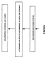
- Figure 4 shows a flow diagram showing some of the control steps to be carried out by the micro controller of figure 3, or by a corresponding controller for a damping element such as the attenuator shown in figure 2.
- the first step involves determining if the output power level is to be changed. As discussed, this can involve checking various inputs to the micro controller. Next, the amount of the total change in level may be determined. This step may be unnecessary, if the output is simply to follow the input but at a different rate of change. The amount of desired change may nevertheless be useful in the next step, of determining the rate of change. This may involve checking inputs to the micro controller, to see if there is an urgent alarm, which might merit a more rapid rate of change than a normal switch on/switch off situation. From the rate of change, the amount of change for the current cycle can be determined. The loop gain K is set to achieve the desired rate of change.
- the next step is to alter the power level output by the transmitter, by first of all altering the set level, at a desired rate.
- a control loop then tries to achieve the new set level.
- the timing of this control loop should be set so that it runs at least ten times as fast as the loop controlling the power set level, so that phase changes in one loop do not affect the other loop.
- the loop back to change the set level again may be exited after a given time or a given number of iterations, or, as shown in figure 4 by ascertaining that the change has been completed.
- Figure 5 shows in schematic form the particular example of how the micro controller may react to a switch-off instruction. After detecting such an instruction, the set point of the transmitter can be controlled to fade off gradually, as shown in figure 4. Finally, the optical source in the transmitter can be switched off.
- Figure 6 shows an optical transmission system including a transmitter 11, an attenuator 12, and a receiver 13.
- the attenuator 12 is controlled by a control means 14.
- the control means 14 is operable in response to a fade-in/fade-out control means 15.
- the fade-in/fade-out control means is itself operable according to the optical signal power level detected at the input to the attenuator 12, or the output of the transmitter 11.
- the attenuator 12 or an equivalent damping element may be located anywhere in the optical link, before an optical element which is sensitive to power changes, such as the receiver 13, or an optical amplifier. Electrically controllable attenuators using faraday rotation might be suitable and have been announced recently by Fujitsu.
- control means 14, and the fade-in/fade-out control means 15 can be implemented by a conventional micro controller, and associated circuitry as described above.
- the attenuator could be controlled additionally on the basis of a intercepted instruction to the transmitter to change the power level.
- the fade-in/fade-out control means could be operable in response to the signal power measured at the output of the attenuator, as well, or instead of the power measured at the input to the attenuator.
- the response time of the control means 14 and the fade-in/fade-out control means 15 will be finite, and therefore the attenuator may be unable to completely damp extremely rapid transitions in power level. Nevertheless, it will have a beneficial effect for a range of types of power level transition which might otherwise disturb sensitive optical elements downstream.
- FIG. 7 shows in schematic form some of the features of the invention.
- a damping means 73 is provided in the optical path, leading to an optical element 71 which is sensitive to changes in the power of the optical signal.
- the damping means which may be incorporated in the transmitter as an alternative, or as well as being in the optical path, is controlled by a control means 74.
- the control means 74 is responsive to means for determining a change in the optical power, 72. The change can be determined by extrapolating from measurements of optical power or can be ascertained from instructions to change the power level, or from detecting alarms which indicate conditions which may lead to a change in power level.
- the pump power of the optical amplifier may be controlled in response to the power measured in a subset of wavelength bands in the optical signal. If the subset is chosen to be those bands which are closest to upper and/or lower power thresholds, then the total power can be controlled with reduced power margins. This is described in some detail in another U.S. patent application by the same inventor, entitled “ Power control for optical element” (ref 'Roberts 14'), incorporated herein by reference.
Landscapes
- Physics & Mathematics (AREA)
- Engineering & Computer Science (AREA)
- Computer Networks & Wireless Communication (AREA)
- Signal Processing (AREA)
- Electromagnetism (AREA)
- Optics & Photonics (AREA)
- Optical Communication System (AREA)
- Lasers (AREA)
Applications Claiming Priority (2)
| Application Number | Priority Date | Filing Date | Title |
|---|---|---|---|
| US08/735,759 US6031647A (en) | 1996-10-23 | 1996-10-23 | Stable power control for optical transmission systems |
| US735759 | 1996-10-23 |
Publications (3)
| Publication Number | Publication Date |
|---|---|
| EP0838913A2 true EP0838913A2 (de) | 1998-04-29 |
| EP0838913A3 EP0838913A3 (de) | 2000-10-11 |
| EP0838913B1 EP0838913B1 (de) | 2006-11-15 |
Family
ID=24957070
Family Applications (1)
| Application Number | Title | Priority Date | Filing Date |
|---|---|---|---|
| EP97307814A Expired - Lifetime EP0838913B1 (de) | 1996-10-23 | 1997-10-03 | Stabilisierte Leistungsregelung für optische Übertragungssysteme |
Country Status (4)
| Country | Link |
|---|---|
| US (2) | US6031647A (de) |
| EP (1) | EP0838913B1 (de) |
| JP (1) | JP4191274B2 (de) |
| DE (1) | DE69736942T2 (de) |
Cited By (9)
| Publication number | Priority date | Publication date | Assignee | Title |
|---|---|---|---|---|
| FR2773620A1 (fr) * | 1998-01-14 | 1999-07-16 | Fujitsu Ltd | Station terminale de telecommunications optiques, procede de transmission de signaux optiques, et procede d'accroissement des signaux optiques dans un systeme a multiplexage de longueurs d'onde |
| WO2000072479A1 (en) * | 1999-05-21 | 2000-11-30 | Corvis Corporation | Method and apparatus for optical transmission control using compensating channels |
| EP1076387A2 (de) * | 1999-08-13 | 2001-02-14 | Marconi Communications Limited | Kontrollverfahren für einen Laser in Wellenlängenmultiplexbasierte Anwendungen |
| US6545799B1 (en) | 1998-09-02 | 2003-04-08 | Corning Incorporated | Method and apparatus for optical system link control |
| EP1484851A1 (de) * | 2003-06-06 | 2004-12-08 | Fujitsu Limited | Abstimmbares optisches Faraday-Dämpfungsglied und damit ausgerüsteter optischer Sender |
| US6907195B2 (en) | 2001-08-28 | 2005-06-14 | Dorsal Networks, Inc. | Terminals having sub-band substitute signal control in optical communication systems |
| US6944399B2 (en) | 2001-08-28 | 2005-09-13 | Dorsal Networks, Inc. | Methods of signal substitution for maintenance of amplifier saturation |
| EP1211763A4 (de) * | 1999-08-23 | 2007-12-05 | Fujitsu Ltd | Wellenlängenmultiplexer |
| EP2367302A1 (de) * | 2010-03-10 | 2011-09-21 | Fujitsu Limited | Optischer Polarisationswellen-Multiplexing-Sende-Empfänger und Steuerverfahren für ein optisches Polarisationswellen-Multiplexing-Signal |
Families Citing this family (54)
| Publication number | Priority date | Publication date | Assignee | Title |
|---|---|---|---|---|
| US6031647A (en) * | 1996-10-23 | 2000-02-29 | Nortel Networks Corporation | Stable power control for optical transmission systems |
| DE19734957C1 (de) * | 1997-08-13 | 1998-12-24 | Lucent Tech Network Sys Gmbh | Verfahren und Anordnung zur Wellenlängenstabilisierung für mehrkanalige optische Übertragungssysteme |
| US6301031B2 (en) * | 1997-09-02 | 2001-10-09 | Agere Systems Optoelectronics Guardian Corp. | Method and apparatus for wavelength-channel tracking and alignment within an optical communications system |
| US5923450A (en) * | 1998-09-30 | 1999-07-13 | Alcatel Network Systems, Inc. | Optical channel regulator and method |
| JP3829962B2 (ja) * | 1998-01-22 | 2006-10-04 | 富士通株式会社 | 光アッテネータ並びに該光アッテネータを備えたシステム、光増幅器及び端局装置 |
| JPH11252047A (ja) * | 1998-03-04 | 1999-09-17 | Fujitsu Ltd | 光波長多重システム、及びその端局 |
| JP3565313B2 (ja) * | 1998-05-25 | 2004-09-15 | 富士通株式会社 | 光送信機並びに該光送信機を有する端局装置及び光通信システム |
| DE19843206A1 (de) * | 1998-09-16 | 2000-04-20 | Siemens Ag | Optische Sendeeinrichtung |
| JP2000241778A (ja) * | 1999-02-19 | 2000-09-08 | Fujitsu Ltd | 光通信装置および光分岐・挿入装置 |
| US6275329B1 (en) * | 1999-05-10 | 2001-08-14 | Oni Systems Corp. | Method and apparatus for amplification of an optical signal |
| CA2409726A1 (en) * | 2000-03-06 | 2001-09-13 | Lightchip, Inc. | Optical power managed network node for processing wavelength division multiplexed optical signals |
| US6449068B1 (en) * | 2000-03-06 | 2002-09-10 | Lightchip, Inc. | Optical power managed network node for processing dense wavelength division multiplexed optical signals |
| JP3363133B2 (ja) * | 2000-07-21 | 2003-01-08 | 住友電気工業株式会社 | 波長多重分割伝送方法およびそのシステム |
| US6643466B1 (en) * | 2000-09-29 | 2003-11-04 | Lucent Technologies Inc. | Method and apparatus for controlling signal power level in free space communication |
| GB0105629D0 (en) * | 2001-03-07 | 2001-04-25 | Marconi Comm Ltd | A transmitter system |
| US7242863B2 (en) * | 2001-05-09 | 2007-07-10 | Ciena Corporation | Method and system for coordinating and utilizing channel power information in an optical communications network |
| JP4569064B2 (ja) * | 2001-09-27 | 2010-10-27 | 住友電気工業株式会社 | 光送信機及び波長分割多重伝送システム |
| US6744964B1 (en) * | 2001-12-20 | 2004-06-01 | Ciena Corporation | System and method for controlling variable optical attenuators |
| US20030133713A1 (en) * | 2002-01-17 | 2003-07-17 | Ng Eddie Kai Ho | Method and system for multi-level power management in an optical network |
| US7058301B2 (en) | 2002-02-28 | 2006-06-06 | Bosloy Jonathan L | Apparatus and method for planned wavelength addition and removal in a wavelength division multiplexed system |
| US7209656B2 (en) * | 2002-04-12 | 2007-04-24 | Fujitsu Limited | Management of optical links using power level information |
| US7212742B2 (en) * | 2002-04-12 | 2007-05-01 | Fujitsu Limited | Power level management in optical networks |
| US7209655B2 (en) * | 2002-04-12 | 2007-04-24 | Fujitsu Limited | Sharing of power level information to support optical communications |
| US6668137B1 (en) * | 2002-06-26 | 2003-12-23 | Nortel Networks Limited | Feed forward optical power control |
| DE10303314A1 (de) * | 2003-01-28 | 2004-07-29 | Marconi Communications Gmbh | Ausgangsstufe für die WDM-Nachrichtenübertragung und Verfahren zum Austauschen von Fülllichtquellen in einer solchen Ausgangsstufe |
| JP4642421B2 (ja) * | 2004-09-27 | 2011-03-02 | 富士通株式会社 | パッケージ始動制御装置 |
| US7643759B2 (en) * | 2005-01-12 | 2010-01-05 | Sumitomo Electric Industries, Ltd. | Signal-quality evaluation device, signal adjustment method, optical-signal evaluation system, and optical transmission system |
| WO2009060522A1 (ja) * | 2007-11-07 | 2009-05-14 | Fujitsu Limited | 光送受信モジュールおよびその管理制御方法,光送受信装置ならびに波長多重光送受信装置 |
| JP5098807B2 (ja) * | 2008-05-22 | 2012-12-12 | 富士通株式会社 | 光信号調整方法及び光信号調整装置 |
| JP2010011098A (ja) * | 2008-06-27 | 2010-01-14 | Fujitsu Ltd | 光伝送装置 |
| JP5198996B2 (ja) * | 2008-09-19 | 2013-05-15 | 住友大阪セメント株式会社 | 光変調器 |
| JP5476697B2 (ja) * | 2008-09-26 | 2014-04-23 | 富士通株式会社 | 光信号送信装置 |
| JP2011188213A (ja) * | 2010-03-08 | 2011-09-22 | Fujitsu Ltd | 光信号送信装置、光増幅装置、光減衰装置及び光信号送信方法 |
| JP2012004691A (ja) * | 2010-06-14 | 2012-01-05 | Nippon Telegr & Teleph Corp <Ntt> | 偏波多重光伝送システム |
| JP2012169757A (ja) * | 2011-02-10 | 2012-09-06 | Nec Corp | 光伝送装置 |
| EP2620446A1 (de) | 2012-01-27 | 2013-07-31 | Laboratorios Del Dr. Esteve, S.A. | Immunogene zur HIV-Impfung |
| JP6387965B2 (ja) * | 2013-09-24 | 2018-09-12 | 日本電気株式会社 | 伝送装置、伝送システム、伝送方法及びプログラムが記憶された記憶媒体 |
| JP2015164264A (ja) * | 2014-02-28 | 2015-09-10 | 富士通株式会社 | 波長多重装置、光伝送装置及び波長多重方法 |
| JP6648437B2 (ja) * | 2015-07-29 | 2020-02-14 | 富士通株式会社 | 送受信システム、送信装置、受信装置及び送受信システムの制御方法 |
| US10142022B1 (en) | 2017-05-24 | 2018-11-27 | Ciena Corporation | Adjustment of control parameters of section of optical fiber network |
| US10439751B2 (en) | 2017-05-24 | 2019-10-08 | Ciena Corporation | Power control in an optical fiber network |
| US11374675B2 (en) * | 2017-06-28 | 2022-06-28 | Huawei Technologies Co., Ltd. | Method and apparatus for modifying channels in an optical medium |
| JP7024234B2 (ja) * | 2017-07-18 | 2022-02-24 | 富士通株式会社 | 光送信機、及び光送信機の制御方法 |
| US10868614B2 (en) | 2018-09-04 | 2020-12-15 | Ciena Corporation | Optical power replacement for faulted spectrum in channel holder based optical links |
| US10547404B1 (en) | 2018-11-13 | 2020-01-28 | Ciena Corporation | Automatic optical link calibration with channel holders |
| US11658745B2 (en) * | 2019-01-15 | 2023-05-23 | Telefonaktiebolaget Lm Ericsson (Publ) | Dispersion compensation |
| US10439709B1 (en) | 2019-02-26 | 2019-10-08 | Ciena Corporation | Handling channel holder failures in channel holder equipped optical links |
| US12587300B2 (en) | 2019-04-09 | 2026-03-24 | Ciena Corporation | Bundling capacity changes in channel holder based optical links |
| US10680737B1 (en) | 2019-04-09 | 2020-06-09 | Ciena Corporation | Bundling capacity changes in channel holder based optical links |
| US12489541B2 (en) | 2019-04-09 | 2025-12-02 | Ciena Corporation | Adaptive bundling for capacity changes in channel holder based optical links |
| TWI810456B (zh) | 2019-05-22 | 2023-08-01 | 美商基利科學股份有限公司 | Tlr7調節化合物及hiv疫苗之組合 |
| US10833791B1 (en) | 2019-06-17 | 2020-11-10 | Ciena Corporation | Reducing interference from channel holders in an optical link |
| AU2020384323A1 (en) | 2019-11-14 | 2022-06-02 | Aelix Therapeutics, S.L. | Dosage regimens for vaccines |
| US11536916B1 (en) * | 2021-05-10 | 2022-12-27 | Amazon Technologies, Inc. | Pathloss optimization for optical systems |
Family Cites Families (22)
| Publication number | Priority date | Publication date | Assignee | Title |
|---|---|---|---|---|
| DE2945055C2 (de) * | 1979-11-08 | 1982-09-02 | Philips Kommunikations Industrie Ag, 8500 Nuernberg | Verfahren und Vorrichtung zum Konstanthalten der in einer Lichtleitfaser geführten Lichtleistung |
| JP2787820B2 (ja) * | 1990-07-20 | 1998-08-20 | キヤノン株式会社 | 波長多重光通信システム及びそこで用いられる光増幅装置 |
| US5088095A (en) * | 1991-01-31 | 1992-02-11 | At&T Bell Laboratories | Gain stabilized fiber amplifier |
| US5225922A (en) * | 1991-11-21 | 1993-07-06 | At&T Bell Laboratories | Optical transmission system equalizer |
| US5276543A (en) * | 1991-11-22 | 1994-01-04 | Gte Laboratories Incorporated | Optical signal equalizer for wavelength division multiplexed optical fiber systems |
| US5500756A (en) * | 1992-02-28 | 1996-03-19 | Hitachi, Ltd. | Optical fiber transmission system and supervision method of the same |
| DE4215338A1 (de) * | 1992-05-09 | 1993-11-11 | Sel Alcatel Ag | Optisches Nachrichtenübertragungssystem mit Überwachungsvorrichtung zur Vermeidung von Riesenimpulsen |
| JPH06132895A (ja) * | 1992-10-20 | 1994-05-13 | Hitachi Ltd | 光パワー変化補償回路及び光伝送装置 |
| FR2707442B1 (fr) * | 1993-07-06 | 1995-09-15 | Pirio Francis | Système de transmission sur fibre optique à compensation des distorsions en ligne. |
| WO1995008879A1 (en) * | 1993-09-22 | 1995-03-30 | Massachussetts Institute Of Technology | Error-rate based laser drive control |
| FR2715017B1 (fr) * | 1994-01-13 | 1996-02-16 | Alcatel Nv | Procédé de transmission et liaison optique à multiplexage spectral avec amplification. |
| JP3379052B2 (ja) * | 1994-09-26 | 2003-02-17 | 富士通株式会社 | 波長多重光増幅装置及び光波長多重伝送システム及び光波長多重伝送方法 |
| JP3432620B2 (ja) * | 1994-12-20 | 2003-08-04 | 富士通株式会社 | 光送信機及びレーザダイオードモジュール |
| JPH08265259A (ja) * | 1995-03-20 | 1996-10-11 | Fujitsu Ltd | 光増幅中継器 |
| JPH08264871A (ja) * | 1995-03-20 | 1996-10-11 | Fujitsu Ltd | 多波長一括光増幅装置 |
| JPH08278523A (ja) * | 1995-04-05 | 1996-10-22 | Hitachi Ltd | 光増幅装置 |
| JP2687933B2 (ja) * | 1995-06-09 | 1997-12-08 | 日本電気株式会社 | 光直接増幅器 |
| JPH0918415A (ja) * | 1995-06-28 | 1997-01-17 | Fujitsu Ltd | 光サージ抑圧光増幅装置 |
| US5739938A (en) * | 1996-09-10 | 1998-04-14 | Northrop Grumman Corporation | Optically-powered directly-modulated fiber optic link |
| US5745275A (en) * | 1996-10-15 | 1998-04-28 | Lucent Technologies Inc. | Multi-channel stabilization of a multi-channel transmitter through correlation feedback |
| US6031647A (en) * | 1996-10-23 | 2000-02-29 | Nortel Networks Corporation | Stable power control for optical transmission systems |
| US6040933A (en) * | 1997-12-19 | 2000-03-21 | Nortel Networks Corporation | Method and apparatus for channel equalization in wavelength division multiplexed systems |
-
1996
- 1996-10-23 US US08/735,759 patent/US6031647A/en not_active Expired - Lifetime
-
1997
- 1997-10-03 EP EP97307814A patent/EP0838913B1/de not_active Expired - Lifetime
- 1997-10-03 DE DE69736942T patent/DE69736942T2/de not_active Expired - Lifetime
- 1997-10-21 JP JP30653897A patent/JP4191274B2/ja not_active Expired - Lifetime
-
1999
- 1999-12-09 US US09/458,209 patent/US6268945B1/en not_active Expired - Lifetime
Cited By (14)
| Publication number | Priority date | Publication date | Assignee | Title |
|---|---|---|---|---|
| FR2773620A1 (fr) * | 1998-01-14 | 1999-07-16 | Fujitsu Ltd | Station terminale de telecommunications optiques, procede de transmission de signaux optiques, et procede d'accroissement des signaux optiques dans un systeme a multiplexage de longueurs d'onde |
| US6823138B2 (en) | 1998-01-14 | 2004-11-23 | Fujitsu Limited | Optical communications terminal station, optical signal transmission method, and optical signal increasing method in wavelength multiplexing system |
| US6545799B1 (en) | 1998-09-02 | 2003-04-08 | Corning Incorporated | Method and apparatus for optical system link control |
| US6563614B1 (en) | 1999-05-21 | 2003-05-13 | Corvis Corporation | Optical transmission system and amplifier control apparatuses and methods |
| AU776273B2 (en) * | 1999-05-21 | 2004-09-02 | Corvis Corporation | Method and apparatus for optical transmission control using compensating channels |
| WO2000072479A1 (en) * | 1999-05-21 | 2000-11-30 | Corvis Corporation | Method and apparatus for optical transmission control using compensating channels |
| US7903978B2 (en) | 1999-05-21 | 2011-03-08 | Broadwing, Llc | Optical transmission systems and amplifier control apparatuses and methods |
| EP1076387A2 (de) * | 1999-08-13 | 2001-02-14 | Marconi Communications Limited | Kontrollverfahren für einen Laser in Wellenlängenmultiplexbasierte Anwendungen |
| EP1211763A4 (de) * | 1999-08-23 | 2007-12-05 | Fujitsu Ltd | Wellenlängenmultiplexer |
| US6907195B2 (en) | 2001-08-28 | 2005-06-14 | Dorsal Networks, Inc. | Terminals having sub-band substitute signal control in optical communication systems |
| US6944399B2 (en) | 2001-08-28 | 2005-09-13 | Dorsal Networks, Inc. | Methods of signal substitution for maintenance of amplifier saturation |
| EP1484851A1 (de) * | 2003-06-06 | 2004-12-08 | Fujitsu Limited | Abstimmbares optisches Faraday-Dämpfungsglied und damit ausgerüsteter optischer Sender |
| EP2367302A1 (de) * | 2010-03-10 | 2011-09-21 | Fujitsu Limited | Optischer Polarisationswellen-Multiplexing-Sende-Empfänger und Steuerverfahren für ein optisches Polarisationswellen-Multiplexing-Signal |
| US8565616B2 (en) | 2010-03-10 | 2013-10-22 | Fujitsu Limited | Polarized-wave-multiplexing optical transmitter and control method of polarized-wave-multiplexed optical signal |
Also Published As
| Publication number | Publication date |
|---|---|
| JP4191274B2 (ja) | 2008-12-03 |
| US6268945B1 (en) | 2001-07-31 |
| JPH10215019A (ja) | 1998-08-11 |
| EP0838913B1 (de) | 2006-11-15 |
| DE69736942T2 (de) | 2007-03-01 |
| US6031647A (en) | 2000-02-29 |
| DE69736942D1 (de) | 2006-12-28 |
| EP0838913A3 (de) | 2000-10-11 |
Similar Documents
| Publication | Publication Date | Title |
|---|---|---|
| US6031647A (en) | Stable power control for optical transmission systems | |
| EP1410535B1 (de) | Verfahren zur leistungsregelung in einem optischen kommunikationssystem | |
| US6819875B2 (en) | Optical wavelength multiplexing transmission apparatus and optical output control method for optical wavelength multiplexing transmission apparatus | |
| US6798567B2 (en) | Method and apparatus for controlling power transients in an optical communication system | |
| EP0926854A2 (de) | Verfahren zum Ausgleichen in WDM-Systemen | |
| JP3833684B2 (ja) | 光受信装置 | |
| JP2004140631A (ja) | 波長多重方法及びその装置 | |
| US6643055B1 (en) | Optical amplifier control | |
| US6342959B1 (en) | Transient suppression in an optical wavelength division multiplexed network | |
| JP2004056245A (ja) | 光伝送装置 | |
| US6207949B1 (en) | Method and apparatus for stabilizing attenuators in optical networks | |
| US10461849B2 (en) | Fast optical link control adaptation using a channel monitor | |
| CA2433486C (en) | Using gain tilt for local compensation of unwanted power gradients | |
| US6668137B1 (en) | Feed forward optical power control | |
| EP1500216B1 (de) | Systeme und verfahren zum kompensieren von signaltransienten | |
| JP2000236301A (ja) | 光波長多重伝送装置の制御方法 | |
| US7746548B2 (en) | Optical amplifier transient control with gain error limits | |
| GB2360654A (en) | Power controlling network element for adding new channels in a controlled manner | |
| JP4983916B2 (ja) | 光再生装置および光再生方法 | |
| JP2024050008A (ja) | 光受信機、光伝送システム、光送信機、光受信方法及び光送信方法 | |
| Sumiya et al. | WDM optical fiber transmission systems | |
| KAWAZAWA et al. | Novel gain tilt monitoring method for DWDM submarine cable systems | |
| HK1042178A1 (en) | Method for controlling power and equalizing in light wavelength division multiplexing system |
Legal Events
| Date | Code | Title | Description |
|---|---|---|---|
| PUAI | Public reference made under article 153(3) epc to a published international application that has entered the european phase |
Free format text: ORIGINAL CODE: 0009012 |
|
| AK | Designated contracting states |
Kind code of ref document: A2 Designated state(s): DE FR GB |
|
| RAP3 | Party data changed (applicant data changed or rights of an application transferred) |
Owner name: NORTEL NETWORKS CORPORATION |
|
| PUAL | Search report despatched |
Free format text: ORIGINAL CODE: 0009013 |
|
| RAP1 | Party data changed (applicant data changed or rights of an application transferred) |
Owner name: NORTEL NETWORKS LIMITED |
|
| AK | Designated contracting states |
Kind code of ref document: A3 Designated state(s): AT BE CH DE DK ES FI FR GB GR IE IT LI LU MC NL PT SE |
|
| 17P | Request for examination filed |
Effective date: 20010411 |
|
| AKX | Designation fees paid |
Free format text: DE FR GB |
|
| RAP1 | Party data changed (applicant data changed or rights of an application transferred) |
Owner name: NORTEL NETWORKS LIMITED |
|
| 17Q | First examination report despatched |
Effective date: 20040216 |
|
| GRAP | Despatch of communication of intention to grant a patent |
Free format text: ORIGINAL CODE: EPIDOSNIGR1 |
|
| GRAS | Grant fee paid |
Free format text: ORIGINAL CODE: EPIDOSNIGR3 |
|
| GRAA | (expected) grant |
Free format text: ORIGINAL CODE: 0009210 |
|
| AK | Designated contracting states |
Kind code of ref document: B1 Designated state(s): DE FR GB |
|
| REG | Reference to a national code |
Ref country code: GB Ref legal event code: FG4D |
|
| REF | Corresponds to: |
Ref document number: 69736942 Country of ref document: DE Date of ref document: 20061228 Kind code of ref document: P |
|
| ET | Fr: translation filed | ||
| PLBE | No opposition filed within time limit |
Free format text: ORIGINAL CODE: 0009261 |
|
| STAA | Information on the status of an ep patent application or granted ep patent |
Free format text: STATUS: NO OPPOSITION FILED WITHIN TIME LIMIT |
|
| 26N | No opposition filed |
Effective date: 20070817 |
|
| REG | Reference to a national code |
Ref country code: GB Ref legal event code: 732E Free format text: REGISTERED BETWEEN 20101230 AND 20110105 |
|
| REG | Reference to a national code |
Ref country code: FR Ref legal event code: TP |
|
| REG | Reference to a national code |
Ref country code: DE Ref legal event code: R082 Ref document number: 69736942 Country of ref document: DE Representative=s name: PATENTANWAELTE WALLACH, KOCH & PARTNER, DE |
|
| REG | Reference to a national code |
Ref country code: DE Ref legal event code: R082 Ref document number: 69736942 Country of ref document: DE Representative=s name: PATENTANWAELTE WALLACH, KOCH, DR. HAIBACH, FEL, DE Effective date: 20120213 Ref country code: DE Ref legal event code: R082 Ref document number: 69736942 Country of ref document: DE Representative=s name: PATENTANWAELTE WALLACH, KOCH & PARTNER, DE Effective date: 20120213 Ref country code: DE Ref legal event code: R081 Ref document number: 69736942 Country of ref document: DE Owner name: CIENA LUXEMBOURG S.A.R.L., LU Free format text: FORMER OWNER: NORTEL NETWORKS LTD., ST. LAURENT, QUEBEC, CA Effective date: 20120213 |
|
| REG | Reference to a national code |
Ref country code: FR Ref legal event code: PLFP Year of fee payment: 19 |
|
| REG | Reference to a national code |
Ref country code: FR Ref legal event code: PLFP Year of fee payment: 20 |
|
| PGFP | Annual fee paid to national office [announced via postgrant information from national office to epo] |
Ref country code: GB Payment date: 20160928 Year of fee payment: 20 |
|
| PGFP | Annual fee paid to national office [announced via postgrant information from national office to epo] |
Ref country code: FR Payment date: 20160919 Year of fee payment: 20 |
|
| PGFP | Annual fee paid to national office [announced via postgrant information from national office to epo] |
Ref country code: DE Payment date: 20160927 Year of fee payment: 20 |
|
| REG | Reference to a national code |
Ref country code: DE Ref legal event code: R071 Ref document number: 69736942 Country of ref document: DE |
|
| REG | Reference to a national code |
Ref country code: GB Ref legal event code: PE20 Expiry date: 20171002 |
|
| PG25 | Lapsed in a contracting state [announced via postgrant information from national office to epo] |
Ref country code: GB Free format text: LAPSE BECAUSE OF EXPIRATION OF PROTECTION Effective date: 20171002 |