EP0838986A2 - Baie électronique - Google Patents
Baie électronique Download PDFInfo
- Publication number
- EP0838986A2 EP0838986A2 EP97117626A EP97117626A EP0838986A2 EP 0838986 A2 EP0838986 A2 EP 0838986A2 EP 97117626 A EP97117626 A EP 97117626A EP 97117626 A EP97117626 A EP 97117626A EP 0838986 A2 EP0838986 A2 EP 0838986A2
- Authority
- EP
- European Patent Office
- Prior art keywords
- angle
- leg
- cover plate
- bracket
- screw
- Prior art date
- Legal status (The legal status is an assumption and is not a legal conclusion. Google has not performed a legal analysis and makes no representation as to the accuracy of the status listed.)
- Granted
Links
Images


Classifications
-
- H—ELECTRICITY
- H05—ELECTRIC TECHNIQUES NOT OTHERWISE PROVIDED FOR
- H05K—PRINTED CIRCUITS; CASINGS OR CONSTRUCTIONAL DETAILS OF ELECTRIC APPARATUS; MANUFACTURE OF ASSEMBLAGES OF ELECTRICAL COMPONENTS
- H05K9/00—Screening of apparatus or components against electric or magnetic fields
- H05K9/0007—Casings
- H05K9/0015—Gaskets or seals
- H05K9/0016—Gaskets or seals having a spring contact
-
- H—ELECTRICITY
- H05—ELECTRIC TECHNIQUES NOT OTHERWISE PROVIDED FOR
- H05K—PRINTED CIRCUITS; CASINGS OR CONSTRUCTIONAL DETAILS OF ELECTRIC APPARATUS; MANUFACTURE OF ASSEMBLAGES OF ELECTRICAL COMPONENTS
- H05K7/00—Constructional details common to different types of electric apparatus
- H05K7/02—Arrangements of circuit components or wiring on supporting structure
- H05K7/12—Resilient or clamping means for holding component to structure
Definitions
- the invention relates to a rack for receiving electrical and electronic components equipped plug-in modules, with two parallel Sidewalls connected by at least four module rails are, each with a cover plate on its top and on its bottom, with rows of holes for fastening screws on the top and bottom Edges of the side walls and with at least one fastening element, which attached to the row of holes and to which the cover plate is attached.
- the invention is applied to subracks of all types and dimensions, for use in equipment cabinets, housings or racks for the Industrial electronics are provided.
- Subrack as in the manner of a frame made of two side walls assembled with at least four connecting rails are often used to protect their internals with upper and lower cover plates Mistake.
- cover plates primarily protect the internals against mechanical damage during transport or during operation, they can also serve as shielding. Prevent in this function the radiation of high-frequency interference.
- the cover plates must consequently not only have sufficient mechanical stability and be perfectly connected to the side walls, but also electrically conductive communicate with the two side walls.
- cover plates and module rails for subracks are described, for example, in DE 42 23 322 of the applicant, it happens through in longitudinal channels of the module rails provided with spring elements engaging edge strips of the cover plates.
- cover plates have been attached to the side walls simply by screw connections, for which purpose the cover plates are folded on the side are and provided with threads for receiving fastening screws will.
- Another disadvantage of this type of attachment is that a variety of cover plate variants must be available, with which the different Mounting options of the modular rails is taken into account. A Subsequent movement of the module rails in other positions is only possible after Removal of a section of the sidebars possible. Because of the distances between the fastening points of the fastening screws sitting next to each other in a row is good high frequency shielding only when used a larger number of screws possible.
- a subrack in which conductive contact springs with an S-shaped cross section a low-resistance connection between the metallic side walls connected by modular rails Manufacture aluminum and the upper or lower cover plate.
- the side The ends of the cover plates are folded at right angles and are channel-shaped half of the contact springs, while the others, oppositely opened halves under spring tension around the edges of the Lay side walls.
- the attached contact springs make it a reliable one HF-like sealing of the gaps between the cover plates and achieved the side walls, however, there is no mechanical connection between the sheets and the walls (DE 42 37 447).
- the fastener is an angle bracket is made of thin, spring-elastic steel sheet and two angle legs has an angle that is more than ninety degrees, that the first angle leg of the angle bracket between the side wall and Cover plate is inserted that the first angle leg has a screw receptacle for the mounting screw that carries the connecting screw through a hole the row of holes is passed through and screwed into the screw holder, that the second angle leg at least one by punching out this angle leg manufactured support for the cover plate that this second Angle leg together with the support a U-shaped spring clip forms, and that the bracket for receiving the abutting the side wall Cover plate serves.
- a screw holder can be made from a Punch and embossed hole are used.
- the first angle leg advantageously has a bevel that leads to the second Angled leg is directed. This measure facilitates the onset of with the fastening elements equipped cover plates, because the slope the first angle legs on the inner edges of the side walls passed.
- Another embodiment of the invention is characterized by on the end faces of the angular support molded angular parts with two legs, one of which has a bracket for the cover plate and the other leg with the bracket forms a resilient, U-shaped receptacle for the cover plate.
- This corner piece serves to extend the fasteners without an additional Screwing it to the side wall is required, it will do the HF sealing the gap between the cover plate and side wall expanded.
- One leg of the angle part expediently has a contact tip on its outside on that are provided to improve contact on the side wall is.
- the one leg of the angular part advantageously has one to the second leg turn towards. This turn serves to facilitate the insertion the cover plates as well as the fold of the first angle leg the fastener.
- a predetermined breaking point can be between the angle bracket and the angle part slight breaking of the angular part can be provided in the event that this part is not needed.
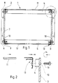
- the subrack shown in simplified form in a vertical section in FIG 1 is used to hold plug-in modules (not shown) which are used for Equipped with electrical and electronic components, one circuit card each have on which sits a front panel.
- the subrack 1 has two parallel side walls 2 and 3 Aluminum sheet and four profiled aluminum rails on top of which the front upper and front lower module rails 4 and 5 can be seen are.
- the side walls 2 and 3 are equipped with fastening flanges 6, have the screw holes with the help of which the rack 1 in one Device cabinet or can be attached to a frame.
- the side walls 2 and 3 are made using (not shown) Screws are screwed to the module rails 4 and 5, for this purpose in the upper and lower edges 8 and 9 of the side walls 2 and 3 rows of holes 10 provided.
- Two cover plates 11 and 12 are used to close the subrack 1, which are detachably attached to the top and bottom.
- Fastening elements are used to fasten the two cover plates 11 and 12 which are attached to the rows of holes 10 and on which the cover plate in question 11 or 12 is held with its edge.
- the fasteners connect the cover plates 11 and 12 both mechanically as electrical with the side walls 2 and 3. With these fasteners it is angular support 13 made of a thin, spring-elastic Sheet steel, preferably made of chrome-nickel steel, by a number in succession following stamping and embossing steps are produced.
- Each angle bracket 13 has - see Figure 3 - a first angle leg 14 and a second angle leg 15. These two angle legs 14, 15 include an angle 16 that is ninety degrees (or slightly more) is.
- the first angle leg 14 has a bevel 17, which for second angle leg 15 is directed and an obtuse angle of about one hundred and seventy-five degrees with the first angle leg 14 includes.
- the first angle leg 14 is between the relevant cover plate 11 or 12 and the adjacent side wall 2 or 3 used. It carries a screw receptacle 18 for a fastening screw 19.
- This fastening screw is from the outside through a hole in the row of holes 10 passed and screwed into the screw receptacle 18 with its thread.
- the screw receptacle 18 is one with two Punched hole with marginal recesses, the edges of which are embossed the shape of two half threads is given - compare FIG. 4, 6 and 7.
- the screw receptacle 18 can also be a flat screw nut.
- the second angle leg 15 has two supports 20 for the cover plate in question 11 and 12, respectively, which are punched out by the second angle leg 15 are manufactured. Together with the second angle leg 15, these two form Pads 20 two U-shaped, resilient brackets 21, which hold the Edge of the relevant, abutting the respective side wall 2 or 3 Cover plates 11 and 12 serve. An insertion bevel 22 facilitates insertion of the cover plate 11, 12 in the brackets 21.
- an angle part 23 is formed, which has two legs 24, 25, which in turn form an angle of ninety Include degrees of angle with each other, the angle can also be somewhat larger than ninety degrees.
- an inward Console 26 which with the other leg 25 is a resilient, U-shaped Receptacle 27 for sliding onto the edge of the cover plate 11 or 12 forms.
- One leg 24 has on its outside a stamped one Contact tip 28 which, when the cover plate 11, 12 is mounted, on the inside the relevant side wall 2 or 3 due to the angular position of the two Leg 24 and 25 of the angle part 23 presses resiliently.
- An impressed predetermined breaking point is between the angle bracket 13 and the angle part 23 29 provided.
- One leg 24 of the angled part 23 points towards the second leg 25 directed turn 30 on.
- angle part 23 there is a further angle part 31 that matches it molded on, which is followed by a further angle bracket 32, which in turn is identical to the angle bracket 13.
- Several angle brackets 13, 32 and several Angle parts 23 and 31 hang, connected to each other via predetermined breaking points 29, to each other.
Landscapes
- Engineering & Computer Science (AREA)
- Microelectronics & Electronic Packaging (AREA)
- Casings For Electric Apparatus (AREA)
- Shielding Devices Or Components To Electric Or Magnetic Fields (AREA)
- Mounting Components In General For Electric Apparatus (AREA)
- Mounting Of Printed Circuit Boards And The Like (AREA)
- Details Of Aerials (AREA)
Applications Claiming Priority (2)
| Application Number | Priority Date | Filing Date | Title |
|---|---|---|---|
| DE19644418A DE19644418C5 (de) | 1996-10-25 | 1996-10-25 | Baugruppenträger |
| DE19644418 | 1996-10-25 |
Publications (3)
| Publication Number | Publication Date |
|---|---|
| EP0838986A2 true EP0838986A2 (fr) | 1998-04-29 |
| EP0838986A3 EP0838986A3 (fr) | 1998-06-10 |
| EP0838986B1 EP0838986B1 (fr) | 1999-12-01 |
Family
ID=7809995
Family Applications (1)
| Application Number | Title | Priority Date | Filing Date |
|---|---|---|---|
| EP97117626A Expired - Lifetime EP0838986B1 (fr) | 1996-10-25 | 1997-10-11 | Baie électronique |
Country Status (12)
| Country | Link |
|---|---|
| EP (1) | EP0838986B1 (fr) |
| JP (1) | JP2866638B2 (fr) |
| KR (1) | KR100286397B1 (fr) |
| AU (1) | AU698965B2 (fr) |
| CA (1) | CA2218441C (fr) |
| CZ (1) | CZ285189B6 (fr) |
| DE (1) | DE19644418C5 (fr) |
| ID (1) | ID18686A (fr) |
| MY (1) | MY132643A (fr) |
| PL (1) | PL183710B1 (fr) |
| SG (1) | SG53108A1 (fr) |
| TW (1) | TW417941U (fr) |
Cited By (1)
| Publication number | Priority date | Publication date | Assignee | Title |
|---|---|---|---|---|
| WO1999051842A1 (fr) | 1998-04-03 | 1999-10-14 | Jozef Cervenko | Element de fixation pour fixer des materiaux plats et procede de fixation desdits materiaux |
Families Citing this family (5)
| Publication number | Priority date | Publication date | Assignee | Title |
|---|---|---|---|---|
| DE19817089C1 (de) * | 1998-04-17 | 1999-08-19 | Schroff Gmbh | Baugruppenträger |
| ATE240631T1 (de) * | 1998-10-01 | 2003-05-15 | Rittal Electronic Systems Gmbh | Vorrichtung zur aufnahme von elektrischen flachbaugruppen, insbesondere baugruppenträger |
| DE29817536U1 (de) * | 1998-10-01 | 1999-11-25 | Siemens AG, 80333 München | Vorrichtung zur Aufnahme von elektrischen Flachbaugruppen, insbesondere Baugruppenträger |
| DE29819941U1 (de) * | 1998-11-07 | 2000-03-23 | AEG Intermas GmbH, 64546 Mörfelden-Walldorf | Baugruppenträger |
| DE102019204704A1 (de) * | 2019-04-02 | 2020-10-08 | Te Connectivity Germany Gmbh | Aufwickelbarer Stanzstreifen mit erhöhter Flexibilität |
Family Cites Families (10)
| Publication number | Priority date | Publication date | Assignee | Title |
|---|---|---|---|---|
| DE9003209U1 (de) * | 1990-03-19 | 1991-07-18 | Siemens Nixdorf Informationssysteme AG, 4790 Paderborn | Kontaktleiste für eine störstrahlungsdichte Verbindung benachbarter metallischer Wandelemente |
| DE59001864D1 (de) * | 1990-04-24 | 1993-07-29 | Loh Kg Rittal Werk | Baugruppentraeger. |
| DE4110800C1 (fr) * | 1991-04-04 | 1992-07-23 | Schroff Gmbh, 7541 Straubenhardt, De | |
| DE9209519U1 (de) * | 1992-07-16 | 1992-08-27 | Schroff Gmbh, 7541 Straubenhardt | HF-dichter Baugruppenträger |
| DE4223322C1 (fr) * | 1992-07-16 | 1993-07-29 | Schroff Gmbh, 7541 Straubenhardt, De | |
| DE4237447A1 (de) * | 1992-11-06 | 1994-05-11 | Licentia Gmbh | Baugruppenträger |
| DE9401533U1 (de) * | 1994-01-27 | 1994-04-07 | Detewe-Deutsche Telephonwerke Ag & Co, 10997 Berlin | Kontaktfeder für die Massekontaktierung zwischen Steckbaugruppen und Baugruppenträger |
| US5506751A (en) * | 1994-10-26 | 1996-04-09 | Chatel; Louis R. | Extruded card cage |
| DE19644419C1 (de) * | 1996-10-25 | 1997-11-27 | Schroff Gmbh | Baugruppenträger |
| EP0986092B1 (fr) * | 1996-11-06 | 2003-02-19 | Hamamatsu Photonics K.K. | Multiplicateur d'electrons |
-
1996
- 1996-10-25 DE DE19644418A patent/DE19644418C5/de not_active Expired - Fee Related
-
1997
- 1997-10-11 EP EP97117626A patent/EP0838986B1/fr not_active Expired - Lifetime
- 1997-10-16 CA CA002218441A patent/CA2218441C/fr not_active Expired - Fee Related
- 1997-10-17 SG SG1997003772A patent/SG53108A1/en unknown
- 1997-10-23 PL PL97322800A patent/PL183710B1/pl not_active IP Right Cessation
- 1997-10-23 ID IDP973504A patent/ID18686A/id unknown
- 1997-10-24 AU AU42850/97A patent/AU698965B2/en not_active Ceased
- 1997-10-24 KR KR1019970054575A patent/KR100286397B1/ko not_active Expired - Fee Related
- 1997-10-24 MY MYPI97005030A patent/MY132643A/en unknown
- 1997-10-24 TW TW088217382U patent/TW417941U/zh not_active IP Right Cessation
- 1997-10-27 JP JP9294402A patent/JP2866638B2/ja not_active Expired - Fee Related
- 1997-10-27 CZ CZ973419A patent/CZ285189B6/cs not_active IP Right Cessation
Cited By (1)
| Publication number | Priority date | Publication date | Assignee | Title |
|---|---|---|---|---|
| WO1999051842A1 (fr) | 1998-04-03 | 1999-10-14 | Jozef Cervenko | Element de fixation pour fixer des materiaux plats et procede de fixation desdits materiaux |
Also Published As
| Publication number | Publication date |
|---|---|
| MY132643A (en) | 2007-10-31 |
| JP2866638B2 (ja) | 1999-03-08 |
| EP0838986B1 (fr) | 1999-12-01 |
| DE19644418C1 (de) | 1998-01-15 |
| AU4285097A (en) | 1998-05-21 |
| DE19644418C5 (de) | 2004-10-28 |
| AU698965B2 (en) | 1998-11-12 |
| ID18686A (id) | 1998-04-30 |
| EP0838986A3 (fr) | 1998-06-10 |
| CA2218441A1 (fr) | 1998-04-25 |
| CZ341997A3 (cs) | 1998-05-13 |
| CZ285189B6 (cs) | 1999-06-16 |
| CA2218441C (fr) | 2001-08-07 |
| KR19980033118A (ko) | 1998-07-25 |
| PL322800A1 (en) | 1998-04-27 |
| TW417941U (en) | 2001-01-01 |
| PL183710B1 (pl) | 2002-07-31 |
| KR100286397B1 (ko) | 2001-04-16 |
| JPH10135662A (ja) | 1998-05-22 |
| SG53108A1 (en) | 1998-09-28 |
Similar Documents
| Publication | Publication Date | Title |
|---|---|---|
| DE4223322C1 (fr) | ||
| EP2683230B1 (fr) | Coffret | |
| EP0109557A1 (fr) | Bâti pour éléments développant de la chaleur | |
| EP0650317A1 (fr) | Rack électronique | |
| EP0838987B1 (fr) | Baie électronique | |
| EP0838986B1 (fr) | Baie électronique | |
| DE19817089C1 (de) | Baugruppenträger | |
| DE4215182C2 (de) | Verfahren zur Herstellung einer elektromagnetisch dichten Halterung von zwei metallischen Bauteilen, und abgeschirmter Baugruppenträger mit derartigen Bauteilen | |
| DE1119920B (de) | Einschubtraeger zur Aufnahme von Bauelemente tragenden Einschueben unterschiedlicher Breite | |
| DE2714562A1 (de) | Baugruppentraeger | |
| DE3144131C2 (fr) | ||
| EP0516986B1 (fr) | Rack électronique | |
| EP0596349B1 (fr) | Support pour installation électrique | |
| DE29618629U1 (de) | Baugruppenträger | |
| DE3624756C2 (fr) | ||
| DE29604597U1 (de) | Elektromagnetisch abgeschirmter Baugruppenträger mit variabler Befestigungsanordnung zwischen Etagenschirmblechen und Seitenwandblechen | |
| EP0062108B1 (fr) | Bâti pour éléments électriques pouvant glisser | |
| DE19523257C1 (de) | Baugruppenträger | |
| DE3531733C2 (fr) | ||
| DE3624682A1 (de) | Geraeteeinsatz der nachrichtentechnik | |
| DE4021972A1 (de) | Baugruppentraeger | |
| DE1089812B (de) | Einschubrahmen zur Aufnahme von Bauelemente tragenden Einschueben | |
| DE10048101A1 (de) | Computergehäuse | |
| DE8300446U1 (de) | Vorrichtung zur Befestigung von Geräteträgern, insbesondere von Gehäusen für elektrische oder elektronische Bauteile, an senkrechten Tragelementen | |
| DE9010410U1 (de) | Baugruppenträger |
Legal Events
| Date | Code | Title | Description |
|---|---|---|---|
| PUAI | Public reference made under article 153(3) epc to a published international application that has entered the european phase |
Free format text: ORIGINAL CODE: 0009012 |
|
| PUAL | Search report despatched |
Free format text: ORIGINAL CODE: 0009013 |
|
| AK | Designated contracting states |
Kind code of ref document: A2 Designated state(s): ES FR GB IT |
|
| AK | Designated contracting states |
Kind code of ref document: A3 Designated state(s): AT BE CH DE DK ES FI FR GB GR IE IT LI LU MC NL PT SE |
|
| 17P | Request for examination filed |
Effective date: 19980703 |
|
| AKX | Designation fees paid |
Free format text: ES FR GB IT |
|
| RBV | Designated contracting states (corrected) |
Designated state(s): ES FR GB IT |
|
| GRAG | Despatch of communication of intention to grant |
Free format text: ORIGINAL CODE: EPIDOS AGRA |
|
| REG | Reference to a national code |
Ref country code: DE Ref legal event code: 8566 |
|
| GRAG | Despatch of communication of intention to grant |
Free format text: ORIGINAL CODE: EPIDOS AGRA |
|
| GRAH | Despatch of communication of intention to grant a patent |
Free format text: ORIGINAL CODE: EPIDOS IGRA |
|
| 17Q | First examination report despatched |
Effective date: 19990324 |
|
| GRAH | Despatch of communication of intention to grant a patent |
Free format text: ORIGINAL CODE: EPIDOS IGRA |
|
| GRAA | (expected) grant |
Free format text: ORIGINAL CODE: 0009210 |
|
| AK | Designated contracting states |
Kind code of ref document: B1 Designated state(s): ES FR GB IT |
|
| PG25 | Lapsed in a contracting state [announced via postgrant information from national office to epo] |
Ref country code: ES Free format text: THE PATENT HAS BEEN ANNULLED BY A DECISION OF A NATIONAL AUTHORITY Effective date: 19991201 |
|
| ITF | It: translation for a ep patent filed | ||
| GBT | Gb: translation of ep patent filed (gb section 77(6)(a)/1977) |
Effective date: 19991206 |
|
| ET | Fr: translation filed | ||
| PLBE | No opposition filed within time limit |
Free format text: ORIGINAL CODE: 0009261 |
|
| STAA | Information on the status of an ep patent application or granted ep patent |
Free format text: STATUS: NO OPPOSITION FILED WITHIN TIME LIMIT |
|
| 26N | No opposition filed | ||
| REG | Reference to a national code |
Ref country code: GB Ref legal event code: IF02 |
|
| PGFP | Annual fee paid to national office [announced via postgrant information from national office to epo] |
Ref country code: IT Payment date: 20091023 Year of fee payment: 13 Ref country code: GB Payment date: 20091023 Year of fee payment: 13 Ref country code: FR Payment date: 20091110 Year of fee payment: 13 |
|
| GBPC | Gb: european patent ceased through non-payment of renewal fee |
Effective date: 20101011 |
|
| PG25 | Lapsed in a contracting state [announced via postgrant information from national office to epo] |
Ref country code: FR Free format text: LAPSE BECAUSE OF NON-PAYMENT OF DUE FEES Effective date: 20101102 |
|
| REG | Reference to a national code |
Ref country code: FR Ref legal event code: ST Effective date: 20110630 |
|
| PG25 | Lapsed in a contracting state [announced via postgrant information from national office to epo] |
Ref country code: GB Free format text: LAPSE BECAUSE OF NON-PAYMENT OF DUE FEES Effective date: 20101011 |
|
| PG25 | Lapsed in a contracting state [announced via postgrant information from national office to epo] |
Ref country code: IT Free format text: LAPSE BECAUSE OF NON-PAYMENT OF DUE FEES Effective date: 20101011 |