EP0839634A2 - Laserschweissen von Angioplastic Ballonkatheter - Google Patents
Laserschweissen von Angioplastic Ballonkatheter Download PDFInfo
- Publication number
- EP0839634A2 EP0839634A2 EP98200064A EP98200064A EP0839634A2 EP 0839634 A2 EP0839634 A2 EP 0839634A2 EP 98200064 A EP98200064 A EP 98200064A EP 98200064 A EP98200064 A EP 98200064A EP 0839634 A2 EP0839634 A2 EP 0839634A2
- Authority
- EP
- European Patent Office
- Prior art keywords
- dilatation member
- dilatation
- energy
- polymeric
- catheter
- Prior art date
- Legal status (The legal status is an assumption and is not a legal conclusion. Google has not performed a legal analysis and makes no representation as to the accuracy of the status listed.)
- Granted
Links
- 238000002399 angioplasty Methods 0.000 title description 5
- 239000000463 material Substances 0.000 claims abstract description 39
- 238000000034 method Methods 0.000 claims abstract description 31
- 230000004927 fusion Effects 0.000 claims abstract description 20
- 239000012530 fluid Substances 0.000 claims abstract description 13
- 238000010521 absorption reaction Methods 0.000 claims abstract description 9
- 239000012141 concentrate Substances 0.000 claims abstract description 4
- 230000003595 spectral effect Effects 0.000 claims abstract description 4
- 239000011248 coating agent Substances 0.000 claims description 2
- 238000000576 coating method Methods 0.000 claims description 2
- 239000000969 carrier Substances 0.000 claims 2
- 230000003287 optical effect Effects 0.000 claims 2
- 238000002425 crystallisation Methods 0.000 description 20
- 230000008025 crystallization Effects 0.000 description 20
- 238000013459 approach Methods 0.000 description 9
- RYGMFSIKBFXOCR-UHFFFAOYSA-N Copper Chemical compound [Cu] RYGMFSIKBFXOCR-UHFFFAOYSA-N 0.000 description 6
- 229910052802 copper Inorganic materials 0.000 description 6
- 239000010949 copper Substances 0.000 description 6
- 239000013307 optical fiber Substances 0.000 description 6
- 210000001367 artery Anatomy 0.000 description 5
- 230000008901 benefit Effects 0.000 description 4
- 229920000728 polyester Polymers 0.000 description 4
- -1 polyethylene terephthalate Polymers 0.000 description 4
- 229920000139 polyethylene terephthalate Polymers 0.000 description 4
- 239000005020 polyethylene terephthalate Substances 0.000 description 4
- 229920000642 polymer Polymers 0.000 description 4
- 238000010276 construction Methods 0.000 description 3
- 238000009826 distribution Methods 0.000 description 3
- 230000001965 increasing effect Effects 0.000 description 3
- 208000014674 injury Diseases 0.000 description 3
- 238000004519 manufacturing process Methods 0.000 description 3
- 229920000098 polyolefin Polymers 0.000 description 3
- 230000035939 shock Effects 0.000 description 3
- 238000000862 absorption spectrum Methods 0.000 description 2
- 239000000853 adhesive Substances 0.000 description 2
- 230000001070 adhesive effect Effects 0.000 description 2
- 229920001577 copolymer Polymers 0.000 description 2
- 238000005520 cutting process Methods 0.000 description 2
- 238000010438 heat treatment Methods 0.000 description 2
- 238000002329 infrared spectrum Methods 0.000 description 2
- 230000005855 radiation Effects 0.000 description 2
- 238000012360 testing method Methods 0.000 description 2
- 230000008733 trauma Effects 0.000 description 2
- 239000004677 Nylon Substances 0.000 description 1
- 239000004952 Polyamide Substances 0.000 description 1
- 239000004698 Polyethylene Substances 0.000 description 1
- 239000004743 Polypropylene Substances 0.000 description 1
- 239000004433 Thermoplastic polyurethane Substances 0.000 description 1
- 208000027418 Wounds and injury Diseases 0.000 description 1
- 239000012790 adhesive layer Substances 0.000 description 1
- 230000004323 axial length Effects 0.000 description 1
- 230000015572 biosynthetic process Effects 0.000 description 1
- 210000004204 blood vessel Anatomy 0.000 description 1
- 238000006664 bond formation reaction Methods 0.000 description 1
- 238000007887 coronary angioplasty Methods 0.000 description 1
- 230000006378 damage Effects 0.000 description 1
- 239000003814 drug Substances 0.000 description 1
- 229940079593 drug Drugs 0.000 description 1
- 230000002708 enhancing effect Effects 0.000 description 1
- 239000000835 fiber Substances 0.000 description 1
- 238000003780 insertion Methods 0.000 description 1
- 230000037431 insertion Effects 0.000 description 1
- 239000000178 monomer Substances 0.000 description 1
- 229920001778 nylon Polymers 0.000 description 1
- 238000004806 packaging method and process Methods 0.000 description 1
- 229920002647 polyamide Polymers 0.000 description 1
- 229920000573 polyethylene Polymers 0.000 description 1
- 229920001155 polypropylene Polymers 0.000 description 1
- 238000011160 research Methods 0.000 description 1
- 238000007789 sealing Methods 0.000 description 1
- 238000001228 spectrum Methods 0.000 description 1
- 229910001220 stainless steel Inorganic materials 0.000 description 1
- 239000010935 stainless steel Substances 0.000 description 1
- 229920001169 thermoplastic Polymers 0.000 description 1
- 229920002803 thermoplastic polyurethane Polymers 0.000 description 1
- 239000004416 thermosoftening plastic Substances 0.000 description 1
- 238000012546 transfer Methods 0.000 description 1
- 238000001429 visible spectrum Methods 0.000 description 1
Images

Classifications
-
- A—HUMAN NECESSITIES
- A61—MEDICAL OR VETERINARY SCIENCE; HYGIENE
- A61M—DEVICES FOR INTRODUCING MEDIA INTO, OR ONTO, THE BODY; DEVICES FOR TRANSDUCING BODY MEDIA OR FOR TAKING MEDIA FROM THE BODY; DEVICES FOR PRODUCING OR ENDING SLEEP OR STUPOR
- A61M25/00—Catheters; Hollow probes
- A61M25/10—Balloon catheters
- A61M25/1027—Making of balloon catheters
- A61M25/1034—Joining of shaft and balloon
-
- B—PERFORMING OPERATIONS; TRANSPORTING
- B29—WORKING OF PLASTICS; WORKING OF SUBSTANCES IN A PLASTIC STATE IN GENERAL
- B29C—SHAPING OR JOINING OF PLASTICS; SHAPING OF MATERIAL IN A PLASTIC STATE, NOT OTHERWISE PROVIDED FOR; AFTER-TREATMENT OF THE SHAPED PRODUCTS, e.g. REPAIRING
- B29C65/00—Joining or sealing of preformed parts, e.g. welding of plastics materials; Apparatus therefor
- B29C65/02—Joining or sealing of preformed parts, e.g. welding of plastics materials; Apparatus therefor by heating, with or without pressure
- B29C65/14—Joining or sealing of preformed parts, e.g. welding of plastics materials; Apparatus therefor by heating, with or without pressure using wave energy, i.e. electromagnetic radiation, or particle radiation
- B29C65/16—Laser beams
- B29C65/1603—Laser beams characterised by the type of electromagnetic radiation
- B29C65/1612—Infrared [IR] radiation, e.g. by infrared lasers
- B29C65/1622—Far infrared radiation [FIR], e.g. by FIR lasers
-
- B—PERFORMING OPERATIONS; TRANSPORTING
- B29—WORKING OF PLASTICS; WORKING OF SUBSTANCES IN A PLASTIC STATE IN GENERAL
- B29C—SHAPING OR JOINING OF PLASTICS; SHAPING OF MATERIAL IN A PLASTIC STATE, NOT OTHERWISE PROVIDED FOR; AFTER-TREATMENT OF THE SHAPED PRODUCTS, e.g. REPAIRING
- B29C65/00—Joining or sealing of preformed parts, e.g. welding of plastics materials; Apparatus therefor
- B29C65/02—Joining or sealing of preformed parts, e.g. welding of plastics materials; Apparatus therefor by heating, with or without pressure
- B29C65/14—Joining or sealing of preformed parts, e.g. welding of plastics materials; Apparatus therefor by heating, with or without pressure using wave energy, i.e. electromagnetic radiation, or particle radiation
- B29C65/16—Laser beams
- B29C65/1629—Laser beams characterised by the way of heating the interface
- B29C65/1635—Laser beams characterised by the way of heating the interface at least passing through one of the parts to be joined, i.e. laser transmission welding
-
- B—PERFORMING OPERATIONS; TRANSPORTING
- B29—WORKING OF PLASTICS; WORKING OF SUBSTANCES IN A PLASTIC STATE IN GENERAL
- B29C—SHAPING OR JOINING OF PLASTICS; SHAPING OF MATERIAL IN A PLASTIC STATE, NOT OTHERWISE PROVIDED FOR; AFTER-TREATMENT OF THE SHAPED PRODUCTS, e.g. REPAIRING
- B29C65/00—Joining or sealing of preformed parts, e.g. welding of plastics materials; Apparatus therefor
- B29C65/02—Joining or sealing of preformed parts, e.g. welding of plastics materials; Apparatus therefor by heating, with or without pressure
- B29C65/14—Joining or sealing of preformed parts, e.g. welding of plastics materials; Apparatus therefor by heating, with or without pressure using wave energy, i.e. electromagnetic radiation, or particle radiation
- B29C65/16—Laser beams
- B29C65/1629—Laser beams characterised by the way of heating the interface
- B29C65/1654—Laser beams characterised by the way of heating the interface scanning at least one of the parts to be joined
-
- B—PERFORMING OPERATIONS; TRANSPORTING
- B29—WORKING OF PLASTICS; WORKING OF SUBSTANCES IN A PLASTIC STATE IN GENERAL
- B29C—SHAPING OR JOINING OF PLASTICS; SHAPING OF MATERIAL IN A PLASTIC STATE, NOT OTHERWISE PROVIDED FOR; AFTER-TREATMENT OF THE SHAPED PRODUCTS, e.g. REPAIRING
- B29C65/00—Joining or sealing of preformed parts, e.g. welding of plastics materials; Apparatus therefor
- B29C65/02—Joining or sealing of preformed parts, e.g. welding of plastics materials; Apparatus therefor by heating, with or without pressure
- B29C65/14—Joining or sealing of preformed parts, e.g. welding of plastics materials; Apparatus therefor by heating, with or without pressure using wave energy, i.e. electromagnetic radiation, or particle radiation
- B29C65/16—Laser beams
- B29C65/1629—Laser beams characterised by the way of heating the interface
- B29C65/1664—Laser beams characterised by the way of heating the interface making use of several radiators
- B29C65/1667—Laser beams characterised by the way of heating the interface making use of several radiators at the same time, i.e. simultaneous laser welding
-
- B—PERFORMING OPERATIONS; TRANSPORTING
- B29—WORKING OF PLASTICS; WORKING OF SUBSTANCES IN A PLASTIC STATE IN GENERAL
- B29C—SHAPING OR JOINING OF PLASTICS; SHAPING OF MATERIAL IN A PLASTIC STATE, NOT OTHERWISE PROVIDED FOR; AFTER-TREATMENT OF THE SHAPED PRODUCTS, e.g. REPAIRING
- B29C65/00—Joining or sealing of preformed parts, e.g. welding of plastics materials; Apparatus therefor
- B29C65/02—Joining or sealing of preformed parts, e.g. welding of plastics materials; Apparatus therefor by heating, with or without pressure
- B29C65/14—Joining or sealing of preformed parts, e.g. welding of plastics materials; Apparatus therefor by heating, with or without pressure using wave energy, i.e. electromagnetic radiation, or particle radiation
- B29C65/16—Laser beams
- B29C65/1677—Laser beams making use of an absorber or impact modifier
- B29C65/1683—Laser beams making use of an absorber or impact modifier coated on the article
-
- B—PERFORMING OPERATIONS; TRANSPORTING
- B29—WORKING OF PLASTICS; WORKING OF SUBSTANCES IN A PLASTIC STATE IN GENERAL
- B29C—SHAPING OR JOINING OF PLASTICS; SHAPING OF MATERIAL IN A PLASTIC STATE, NOT OTHERWISE PROVIDED FOR; AFTER-TREATMENT OF THE SHAPED PRODUCTS, e.g. REPAIRING
- B29C65/00—Joining or sealing of preformed parts, e.g. welding of plastics materials; Apparatus therefor
- B29C65/02—Joining or sealing of preformed parts, e.g. welding of plastics materials; Apparatus therefor by heating, with or without pressure
- B29C65/14—Joining or sealing of preformed parts, e.g. welding of plastics materials; Apparatus therefor by heating, with or without pressure using wave energy, i.e. electromagnetic radiation, or particle radiation
- B29C65/16—Laser beams
- B29C65/1687—Laser beams making use of light guides
-
- B—PERFORMING OPERATIONS; TRANSPORTING
- B29—WORKING OF PLASTICS; WORKING OF SUBSTANCES IN A PLASTIC STATE IN GENERAL
- B29C—SHAPING OR JOINING OF PLASTICS; SHAPING OF MATERIAL IN A PLASTIC STATE, NOT OTHERWISE PROVIDED FOR; AFTER-TREATMENT OF THE SHAPED PRODUCTS, e.g. REPAIRING
- B29C65/00—Joining or sealing of preformed parts, e.g. welding of plastics materials; Apparatus therefor
- B29C65/66—Joining or sealing of preformed parts, e.g. welding of plastics materials; Apparatus therefor by liberation of internal stresses, e.g. shrinking of one of the parts to be joined
- B29C65/68—Joining or sealing of preformed parts, e.g. welding of plastics materials; Apparatus therefor by liberation of internal stresses, e.g. shrinking of one of the parts to be joined using auxiliary shrinkable elements
-
- B—PERFORMING OPERATIONS; TRANSPORTING
- B29—WORKING OF PLASTICS; WORKING OF SUBSTANCES IN A PLASTIC STATE IN GENERAL
- B29C—SHAPING OR JOINING OF PLASTICS; SHAPING OF MATERIAL IN A PLASTIC STATE, NOT OTHERWISE PROVIDED FOR; AFTER-TREATMENT OF THE SHAPED PRODUCTS, e.g. REPAIRING
- B29C66/00—General aspects of processes or apparatus for joining preformed parts
- B29C66/01—General aspects dealing with the joint area or with the area to be joined
- B29C66/05—Particular design of joint configurations
- B29C66/10—Particular design of joint configurations particular design of the joint cross-sections
- B29C66/11—Joint cross-sections comprising a single joint-segment, i.e. one of the parts to be joined comprising a single joint-segment in the joint cross-section
- B29C66/112—Single lapped joints
- B29C66/1122—Single lap to lap joints, i.e. overlap joints
-
- B—PERFORMING OPERATIONS; TRANSPORTING
- B29—WORKING OF PLASTICS; WORKING OF SUBSTANCES IN A PLASTIC STATE IN GENERAL
- B29C—SHAPING OR JOINING OF PLASTICS; SHAPING OF MATERIAL IN A PLASTIC STATE, NOT OTHERWISE PROVIDED FOR; AFTER-TREATMENT OF THE SHAPED PRODUCTS, e.g. REPAIRING
- B29C66/00—General aspects of processes or apparatus for joining preformed parts
- B29C66/01—General aspects dealing with the joint area or with the area to be joined
- B29C66/345—Progressively making the joint, e.g. starting from the middle
- B29C66/3452—Making complete joints by combining partial joints
-
- B—PERFORMING OPERATIONS; TRANSPORTING
- B29—WORKING OF PLASTICS; WORKING OF SUBSTANCES IN A PLASTIC STATE IN GENERAL
- B29C—SHAPING OR JOINING OF PLASTICS; SHAPING OF MATERIAL IN A PLASTIC STATE, NOT OTHERWISE PROVIDED FOR; AFTER-TREATMENT OF THE SHAPED PRODUCTS, e.g. REPAIRING
- B29C66/00—General aspects of processes or apparatus for joining preformed parts
- B29C66/50—General aspects of joining tubular articles; General aspects of joining long products, i.e. bars or profiled elements; General aspects of joining single elements to tubular articles, hollow articles or bars; General aspects of joining several hollow-preforms to form hollow or tubular articles
- B29C66/51—Joining tubular articles, profiled elements or bars; Joining single elements to tubular articles, hollow articles or bars; Joining several hollow-preforms to form hollow or tubular articles
- B29C66/53—Joining single elements to tubular articles, hollow articles or bars
- B29C66/532—Joining single elements to the wall of tubular articles, hollow articles or bars
- B29C66/5324—Joining single elements to the wall of tubular articles, hollow articles or bars said single elements being substantially annular, i.e. of finite length
- B29C66/53241—Joining single elements to the wall of tubular articles, hollow articles or bars said single elements being substantially annular, i.e. of finite length said articles being tubular and said substantially annular single elements being of finite length relative to the infinite length of said tubular articles
-
- B—PERFORMING OPERATIONS; TRANSPORTING
- B29—WORKING OF PLASTICS; WORKING OF SUBSTANCES IN A PLASTIC STATE IN GENERAL
- B29C—SHAPING OR JOINING OF PLASTICS; SHAPING OF MATERIAL IN A PLASTIC STATE, NOT OTHERWISE PROVIDED FOR; AFTER-TREATMENT OF THE SHAPED PRODUCTS, e.g. REPAIRING
- B29C66/00—General aspects of processes or apparatus for joining preformed parts
- B29C66/50—General aspects of joining tubular articles; General aspects of joining long products, i.e. bars or profiled elements; General aspects of joining single elements to tubular articles, hollow articles or bars; General aspects of joining several hollow-preforms to form hollow or tubular articles
- B29C66/51—Joining tubular articles, profiled elements or bars; Joining single elements to tubular articles, hollow articles or bars; Joining several hollow-preforms to form hollow or tubular articles
- B29C66/53—Joining single elements to tubular articles, hollow articles or bars
- B29C66/534—Joining single elements to open ends of tubular or hollow articles or to the ends of bars
- B29C66/5344—Joining single elements to open ends of tubular or hollow articles or to the ends of bars said single elements being substantially annular, i.e. of finite length, e.g. joining flanges to tube ends
-
- B—PERFORMING OPERATIONS; TRANSPORTING
- B29—WORKING OF PLASTICS; WORKING OF SUBSTANCES IN A PLASTIC STATE IN GENERAL
- B29C—SHAPING OR JOINING OF PLASTICS; SHAPING OF MATERIAL IN A PLASTIC STATE, NOT OTHERWISE PROVIDED FOR; AFTER-TREATMENT OF THE SHAPED PRODUCTS, e.g. REPAIRING
- B29C66/00—General aspects of processes or apparatus for joining preformed parts
- B29C66/50—General aspects of joining tubular articles; General aspects of joining long products, i.e. bars or profiled elements; General aspects of joining single elements to tubular articles, hollow articles or bars; General aspects of joining several hollow-preforms to form hollow or tubular articles
- B29C66/61—Joining from or joining on the inside
- B29C66/612—Making circumferential joints
-
- B—PERFORMING OPERATIONS; TRANSPORTING
- B29—WORKING OF PLASTICS; WORKING OF SUBSTANCES IN A PLASTIC STATE IN GENERAL
- B29C—SHAPING OR JOINING OF PLASTICS; SHAPING OF MATERIAL IN A PLASTIC STATE, NOT OTHERWISE PROVIDED FOR; AFTER-TREATMENT OF THE SHAPED PRODUCTS, e.g. REPAIRING
- B29C66/00—General aspects of processes or apparatus for joining preformed parts
- B29C66/50—General aspects of joining tubular articles; General aspects of joining long products, i.e. bars or profiled elements; General aspects of joining single elements to tubular articles, hollow articles or bars; General aspects of joining several hollow-preforms to form hollow or tubular articles
- B29C66/63—Internally supporting the article during joining
-
- B—PERFORMING OPERATIONS; TRANSPORTING
- B29—WORKING OF PLASTICS; WORKING OF SUBSTANCES IN A PLASTIC STATE IN GENERAL
- B29C—SHAPING OR JOINING OF PLASTICS; SHAPING OF MATERIAL IN A PLASTIC STATE, NOT OTHERWISE PROVIDED FOR; AFTER-TREATMENT OF THE SHAPED PRODUCTS, e.g. REPAIRING
- B29C66/00—General aspects of processes or apparatus for joining preformed parts
- B29C66/50—General aspects of joining tubular articles; General aspects of joining long products, i.e. bars or profiled elements; General aspects of joining single elements to tubular articles, hollow articles or bars; General aspects of joining several hollow-preforms to form hollow or tubular articles
- B29C66/65—General aspects of joining tubular articles; General aspects of joining long products, i.e. bars or profiled elements; General aspects of joining single elements to tubular articles, hollow articles or bars; General aspects of joining several hollow-preforms to form hollow or tubular articles with a relative motion between the article and the welding tool
- B29C66/652—General aspects of joining tubular articles; General aspects of joining long products, i.e. bars or profiled elements; General aspects of joining single elements to tubular articles, hollow articles or bars; General aspects of joining several hollow-preforms to form hollow or tubular articles with a relative motion between the article and the welding tool moving the welding tool around the fixed article
-
- B—PERFORMING OPERATIONS; TRANSPORTING
- B29—WORKING OF PLASTICS; WORKING OF SUBSTANCES IN A PLASTIC STATE IN GENERAL
- B29C—SHAPING OR JOINING OF PLASTICS; SHAPING OF MATERIAL IN A PLASTIC STATE, NOT OTHERWISE PROVIDED FOR; AFTER-TREATMENT OF THE SHAPED PRODUCTS, e.g. REPAIRING
- B29C66/00—General aspects of processes or apparatus for joining preformed parts
- B29C66/70—General aspects of processes or apparatus for joining preformed parts characterised by the composition, physical properties or the structure of the material of the parts to be joined; Joining with non-plastics material
- B29C66/73—General aspects of processes or apparatus for joining preformed parts characterised by the composition, physical properties or the structure of the material of the parts to be joined; Joining with non-plastics material characterised by the intensive physical properties of the material of the parts to be joined, by the optical properties of the material of the parts to be joined, by the extensive physical properties of the parts to be joined, by the state of the material of the parts to be joined or by the material of the parts to be joined being a thermoplastic or a thermoset
- B29C66/739—General aspects of processes or apparatus for joining preformed parts characterised by the composition, physical properties or the structure of the material of the parts to be joined; Joining with non-plastics material characterised by the intensive physical properties of the material of the parts to be joined, by the optical properties of the material of the parts to be joined, by the extensive physical properties of the parts to be joined, by the state of the material of the parts to be joined or by the material of the parts to be joined being a thermoplastic or a thermoset characterised by the material of the parts to be joined being a thermoplastic or a thermoset
- B29C66/7392—General aspects of processes or apparatus for joining preformed parts characterised by the composition, physical properties or the structure of the material of the parts to be joined; Joining with non-plastics material characterised by the intensive physical properties of the material of the parts to be joined, by the optical properties of the material of the parts to be joined, by the extensive physical properties of the parts to be joined, by the state of the material of the parts to be joined or by the material of the parts to be joined being a thermoplastic or a thermoset characterised by the material of the parts to be joined being a thermoplastic or a thermoset characterised by the material of at least one of the parts being a thermoplastic
- B29C66/73921—General aspects of processes or apparatus for joining preformed parts characterised by the composition, physical properties or the structure of the material of the parts to be joined; Joining with non-plastics material characterised by the intensive physical properties of the material of the parts to be joined, by the optical properties of the material of the parts to be joined, by the extensive physical properties of the parts to be joined, by the state of the material of the parts to be joined or by the material of the parts to be joined being a thermoplastic or a thermoset characterised by the material of the parts to be joined being a thermoplastic or a thermoset characterised by the material of at least one of the parts being a thermoplastic characterised by the materials of both parts being thermoplastics
-
- B—PERFORMING OPERATIONS; TRANSPORTING
- B29—WORKING OF PLASTICS; WORKING OF SUBSTANCES IN A PLASTIC STATE IN GENERAL
- B29C—SHAPING OR JOINING OF PLASTICS; SHAPING OF MATERIAL IN A PLASTIC STATE, NOT OTHERWISE PROVIDED FOR; AFTER-TREATMENT OF THE SHAPED PRODUCTS, e.g. REPAIRING
- B29C66/00—General aspects of processes or apparatus for joining preformed parts
- B29C66/80—General aspects of machine operations or constructions and parts thereof
-
- A—HUMAN NECESSITIES
- A61—MEDICAL OR VETERINARY SCIENCE; HYGIENE
- A61M—DEVICES FOR INTRODUCING MEDIA INTO, OR ONTO, THE BODY; DEVICES FOR TRANSDUCING BODY MEDIA OR FOR TAKING MEDIA FROM THE BODY; DEVICES FOR PRODUCING OR ENDING SLEEP OR STUPOR
- A61M25/00—Catheters; Hollow probes
- A61M25/10—Balloon catheters
- A61M25/1027—Making of balloon catheters
- A61M25/1029—Production methods of the balloon members, e.g. blow-moulding, extruding, deposition or by wrapping a plurality of layers of balloon material around a mandril
- A61M2025/1031—Surface processing of balloon members, e.g. coating or deposition; Mounting additional parts onto the balloon member's surface
-
- A—HUMAN NECESSITIES
- A61—MEDICAL OR VETERINARY SCIENCE; HYGIENE
- A61M—DEVICES FOR INTRODUCING MEDIA INTO, OR ONTO, THE BODY; DEVICES FOR TRANSDUCING BODY MEDIA OR FOR TAKING MEDIA FROM THE BODY; DEVICES FOR PRODUCING OR ENDING SLEEP OR STUPOR
- A61M25/00—Catheters; Hollow probes
- A61M25/0009—Making of catheters or other medical or surgical tubes
-
- B—PERFORMING OPERATIONS; TRANSPORTING
- B29—WORKING OF PLASTICS; WORKING OF SUBSTANCES IN A PLASTIC STATE IN GENERAL
- B29C—SHAPING OR JOINING OF PLASTICS; SHAPING OF MATERIAL IN A PLASTIC STATE, NOT OTHERWISE PROVIDED FOR; AFTER-TREATMENT OF THE SHAPED PRODUCTS, e.g. REPAIRING
- B29C35/00—Heating, cooling or curing, e.g. crosslinking or vulcanising; Apparatus therefor
- B29C35/02—Heating or curing, e.g. crosslinking or vulcanizing during moulding, e.g. in a mould
- B29C35/08—Heating or curing, e.g. crosslinking or vulcanizing during moulding, e.g. in a mould by wave energy or particle radiation
- B29C35/0805—Heating or curing, e.g. crosslinking or vulcanizing during moulding, e.g. in a mould by wave energy or particle radiation using electromagnetic radiation
- B29C2035/0822—Heating or curing, e.g. crosslinking or vulcanizing during moulding, e.g. in a mould by wave energy or particle radiation using electromagnetic radiation using IR radiation
-
- B—PERFORMING OPERATIONS; TRANSPORTING
- B29—WORKING OF PLASTICS; WORKING OF SUBSTANCES IN A PLASTIC STATE IN GENERAL
- B29C—SHAPING OR JOINING OF PLASTICS; SHAPING OF MATERIAL IN A PLASTIC STATE, NOT OTHERWISE PROVIDED FOR; AFTER-TREATMENT OF THE SHAPED PRODUCTS, e.g. REPAIRING
- B29C65/00—Joining or sealing of preformed parts, e.g. welding of plastics materials; Apparatus therefor
- B29C65/02—Joining or sealing of preformed parts, e.g. welding of plastics materials; Apparatus therefor by heating, with or without pressure
- B29C65/14—Joining or sealing of preformed parts, e.g. welding of plastics materials; Apparatus therefor by heating, with or without pressure using wave energy, i.e. electromagnetic radiation, or particle radiation
- B29C65/16—Laser beams
- B29C65/1603—Laser beams characterised by the type of electromagnetic radiation
- B29C65/1612—Infrared [IR] radiation, e.g. by infrared lasers
- B29C65/1616—Near infrared radiation [NIR], e.g. by YAG lasers
-
- B—PERFORMING OPERATIONS; TRANSPORTING
- B29—WORKING OF PLASTICS; WORKING OF SUBSTANCES IN A PLASTIC STATE IN GENERAL
- B29C—SHAPING OR JOINING OF PLASTICS; SHAPING OF MATERIAL IN A PLASTIC STATE, NOT OTHERWISE PROVIDED FOR; AFTER-TREATMENT OF THE SHAPED PRODUCTS, e.g. REPAIRING
- B29C65/00—Joining or sealing of preformed parts, e.g. welding of plastics materials; Apparatus therefor
- B29C65/02—Joining or sealing of preformed parts, e.g. welding of plastics materials; Apparatus therefor by heating, with or without pressure
- B29C65/14—Joining or sealing of preformed parts, e.g. welding of plastics materials; Apparatus therefor by heating, with or without pressure using wave energy, i.e. electromagnetic radiation, or particle radiation
- B29C65/16—Laser beams
- B29C65/1603—Laser beams characterised by the type of electromagnetic radiation
- B29C65/1612—Infrared [IR] radiation, e.g. by infrared lasers
- B29C65/1619—Mid infrared radiation [MIR], e.g. by CO or CO2 lasers
-
- B—PERFORMING OPERATIONS; TRANSPORTING
- B29—WORKING OF PLASTICS; WORKING OF SUBSTANCES IN A PLASTIC STATE IN GENERAL
- B29C—SHAPING OR JOINING OF PLASTICS; SHAPING OF MATERIAL IN A PLASTIC STATE, NOT OTHERWISE PROVIDED FOR; AFTER-TREATMENT OF THE SHAPED PRODUCTS, e.g. REPAIRING
- B29C65/00—Joining or sealing of preformed parts, e.g. welding of plastics materials; Apparatus therefor
- B29C65/02—Joining or sealing of preformed parts, e.g. welding of plastics materials; Apparatus therefor by heating, with or without pressure
- B29C65/14—Joining or sealing of preformed parts, e.g. welding of plastics materials; Apparatus therefor by heating, with or without pressure using wave energy, i.e. electromagnetic radiation, or particle radiation
- B29C65/16—Laser beams
- B29C65/1629—Laser beams characterised by the way of heating the interface
- B29C65/1654—Laser beams characterised by the way of heating the interface scanning at least one of the parts to be joined
- B29C65/1661—Laser beams characterised by the way of heating the interface scanning at least one of the parts to be joined scanning repeatedly, e.g. quasi-simultaneous laser welding
-
- B—PERFORMING OPERATIONS; TRANSPORTING
- B29—WORKING OF PLASTICS; WORKING OF SUBSTANCES IN A PLASTIC STATE IN GENERAL
- B29C—SHAPING OR JOINING OF PLASTICS; SHAPING OF MATERIAL IN A PLASTIC STATE, NOT OTHERWISE PROVIDED FOR; AFTER-TREATMENT OF THE SHAPED PRODUCTS, e.g. REPAIRING
- B29C66/00—General aspects of processes or apparatus for joining preformed parts
- B29C66/70—General aspects of processes or apparatus for joining preformed parts characterised by the composition, physical properties or the structure of the material of the parts to be joined; Joining with non-plastics material
- B29C66/71—General aspects of processes or apparatus for joining preformed parts characterised by the composition, physical properties or the structure of the material of the parts to be joined; Joining with non-plastics material characterised by the composition of the plastics material of the parts to be joined
-
- B—PERFORMING OPERATIONS; TRANSPORTING
- B29—WORKING OF PLASTICS; WORKING OF SUBSTANCES IN A PLASTIC STATE IN GENERAL
- B29K—INDEXING SCHEME ASSOCIATED WITH SUBCLASSES B29B, B29C OR B29D, RELATING TO MOULDING MATERIALS OR TO MATERIALS FOR MOULDS, REINFORCEMENTS, FILLERS OR PREFORMED PARTS, e.g. INSERTS
- B29K2995/00—Properties of moulding materials, reinforcements, fillers, preformed parts or moulds
- B29K2995/0037—Other properties
- B29K2995/0049—Heat shrinkable
-
- B—PERFORMING OPERATIONS; TRANSPORTING
- B29—WORKING OF PLASTICS; WORKING OF SUBSTANCES IN A PLASTIC STATE IN GENERAL
- B29K—INDEXING SCHEME ASSOCIATED WITH SUBCLASSES B29B, B29C OR B29D, RELATING TO MOULDING MATERIALS OR TO MATERIALS FOR MOULDS, REINFORCEMENTS, FILLERS OR PREFORMED PARTS, e.g. INSERTS
- B29K2995/00—Properties of moulding materials, reinforcements, fillers, preformed parts or moulds
- B29K2995/0037—Other properties
- B29K2995/0068—Permeability to liquids; Adsorption
- B29K2995/0069—Permeability to liquids; Adsorption non-permeable
-
- B—PERFORMING OPERATIONS; TRANSPORTING
- B29—WORKING OF PLASTICS; WORKING OF SUBSTANCES IN A PLASTIC STATE IN GENERAL
- B29L—INDEXING SCHEME ASSOCIATED WITH SUBCLASS B29C, RELATING TO PARTICULAR ARTICLES
- B29L2022/00—Hollow articles
- B29L2022/02—Inflatable articles
- B29L2022/022—Balloons
-
- B—PERFORMING OPERATIONS; TRANSPORTING
- B29—WORKING OF PLASTICS; WORKING OF SUBSTANCES IN A PLASTIC STATE IN GENERAL
- B29L—INDEXING SCHEME ASSOCIATED WITH SUBCLASS B29C, RELATING TO PARTICULAR ARTICLES
- B29L2031/00—Other particular articles
- B29L2031/753—Medical equipment; Accessories therefor
- B29L2031/7542—Catheters
- B29L2031/7543—Balloon catheters
Definitions
- the present invention relates to dilatation balloon catheters employed in percutaneous transluminal angioplasty (PTA) and percutaneous transluminal coronary angioplasty (PTCA) procedures, and more particularly to the means for forming fluid tight seals between these catheters and their associated dilatation balloons.
- PTA percutaneous transluminal angioplasty
- PTCA percutaneous transluminal coronary angioplasty
- Balloon catheters are well known for their utility in treating certain types of obstructions or occlusions in blood vessels, such as plaque build up.
- Angioplasty catheterization typically involves aligning a balloon catheter within the vessel to position its dilatation balloon at or along the obstruction. Then, fluid under pressure is supplied to the balloon through a balloon inflation lumen in the catheter, expanding the balloon against the obstruction.
- the dilatation balloon is mounted along the distal end region of the catheter and surrounds the catheter.
- a main body portion or media region of the balloon has a diameter substantially larger than that of the catheter, with proximal and distal shafts or neck regions of the balloon having inner diameters substantially equal to the outer diameter of the catheter.
- Proximal and distal tapered portions, or cones join the medal region to the proximal and distal shafts, respectively, with each cone diverging in the direction toward the medial region.
- the bonds between the balloon and catheter are formed along the proximal and distal shafts.
- One known bonding approach for heat fusible materials involves the resistance heating of copper jaws, while the jaws press the respective balloon shafts onto and against the catheter.
- One result of the deformation of the balloon and catheter material is the formation of small, random channels at the balloon/catheter interface, giving rise to variations in the strength of different bonds.
- bonds are given a sufficient length to provide the requisite burst strength, typically axial dimensions in the range of about 0.070-0.150 inches (0.178-0.381 cm).
- the copper jaws heat the balloon shafts and catheter primarily by conduction but also by radiation. The heat causes crystallization and stiffening of the balloon and catheter material, not only at the bond site, but also in both directions axially of the bond, due to heat conduction through the balloon and the catheter, and heat radiation from the jaws.
- Crystallization at the cones can be reduced or avoided by sufficient axial spacing between each of the balloon cones and its associated bond.
- this approach further increases the minimum required length of the distal balloon shaft. More particularly, it has been found that a gap of at least .030 inches (0.0762 cm) between the bond and balloon cone is required, to satisfactorily reduce crystallization in the cone.
- U.S. Patent No. 4,251,305 (Becker et al) discloses a non-contact method for heat sealing a balloon onto a catheter. A length of thin tubing is slid over an elongated shaft of the catheter. Shrink tubing is installed over the thin walled tubing at its ends, and overlapping the shaft, and partially shrunk. Then, lamps provide further radiant energy to form gradually tapering thermoplastic joints that bond the tubing and shaft.
- the device employed for bonding utilizes three lamps that emit energy along the visible and infrared spectra. Each lamp is situated near an elliptical reflector, at one of the foci of the ellipse. The bond or treatment area is near the other focus. While this approach avoids the problems arising from mechanical squeezing from the copper jaws, the undesirable axial conductive heat transfer remains a problem.
- Adhesives can be employed as an alternative to fusion bonding.
- the adhesive layers add to the thickness of the catheter and increase its rigidity at the region of the bonds.
- adhesive bonds are known to be generally inferior to fusion bonds.
- Another object of the invention is to bond dilatation balloons to catheters in a manner to reduce thermal shock to the balloon cones, resulting in softer, more flexible dilatation balloons.
- a further object is to provide balloon catheters with proximal and distal fusion bonds that are narrow, yet able to withstand high burst pressures.
- Yet another object is to provide a balloon catheter more maneuverable along arteries and at reduced risk of trauma to the arteries.
- a balloon catheter including an elongate pliable length of catheter tubing formed of a polymeric material and having a proximal end and a distal end.
- the balloon catheter further includes a polymeric dilatation balloon mounted to the catheter tubing near the distal end and in surrounding relation to the catheter tubing.
- the balloon includes a media region, and proximal and distal shaft regions. Each shaft region is substantially smaller in diameter than the medial region.
- the balloon further includes proximal and distal tapered regions between the medial region and the proximal and distal neck regions, respectively. Each tapered region diverges in the direction from its associated shaft region to the media region.
- Annular proximal and distal fluid tight fusion bonds are formed between the catheter tubing and the proximal and distal shaft regions, respectively.
- Each of the proximal and distal fusion bonds is within .030 inches (0.0762 cm) of its associated one of the proximal and distal tapered regions.
- each of the distal tapered regions is substantially free of crystallization.
- the axial dimension of the distal fusion bond is at most .030 inches (0.0762 cm), and is less than .030 inches (0.0762 cm) from the distal tapered region. This facilitates construction of a balloon catheter having a distal tip length of less than 0.06 inches (0.152 cm), and more preferably less than 0.03 inches (0.0762 cm).
- the shorter distal tip in combination with the virtual absence of crystallization or stiffening of the adjacent balloon tapered region, results in substantially improved catheter maneuverability through convoluted vessels, during catheter insertion and also during catheter withdrawal.
- the catheter may be inserted into and used in vessels heretofore deemed inaccessible, and at substantially less risk of injury to the intima.
- the reduced length distal tip is achieved while maintaining the integrity of the bond, due to a unique process for forming a fluid tight seal between a polymeric body and a polymeric dilatation member surrounding the body.
- the process includes the following steps:
- a preferred process employs a round body and an annular dilatation member, whereby the interface of the first and second surfaces is annular.
- a beam of the monochromatic energy is focused, with the focal area of the beam substantially at the interface.
- the focal area is moved in a annular path along the interface, relative to the body and the dilatation member. This is readily accomplished by mounting the body and dilatation member substantially concentrically on an axis, and rotating the body and dilatation member about the axis while maintaining the beam stationary. Alternatively, the body and dilatation member are maintained stationary, while optomechanical means are employed to rotate the beam about the axis.
- the preferred monochromatic energy is laser energy having a wavelength in the far infrared range, most preferably about 10.6 microns.
- Preferred polymeric materials e.g. Hytrel, (polyester) for the catheter tubing and polyethylene terephthalate for the balloon, are highly absorptive of energy at this wavelength. The high absorption prevents any substantial conduction of heat from the bond site in either direction axially of the catheter. This reduces the energy required to form the fusion bond, and prevents any substantial crystallization and hardening of material in either direction from the bond site.
- a CO 2 laser is used to provide a radiant energy beam at the preferred wavelength, and preferably operated in the tem 00 mode.
- the focal area of the beam has a Gaussian distribution, further enhancing the concentration of heat at the bond site.
- consistent and reliable fusion bonds are formed between catheters and dilatation balloons.
- the bonds are narrow in axial dimension, with relatively slight thermal shock and stiffening to the material near the bond site, in particular the cones or tapered regions of the dilatation balloon.
- the result is a balloon catheter that is more maneuverable, more pliable for a more complete evacuation of radiopaque dye, and more able to withstand high burst pressures.
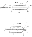
- the balloon catheter includes an elongate and pliable length of catheter tubing 18 constructed of a body compatible polymeric material, preferably a polyester such as that sold under the brand name Hytrel. Other suitable materials include polyolefins, polyamides and thermoplastic polyurethanes, and copolymers of these materials.
- a dilatation balloon 20 surrounds catheter tubing 18 along the distal end region. The dilatation balloon is shown in its fully expanded or dilated configuration, as when the balloon contains a fluid, supplied under pressure to the balloon interior through a balloon inflation lumen (not shown) open to the proximal end of catheter tubing 18 and to the balloon interior.
- dilatation balloon 20 When fully expanded, dilatation balloon 20 includes a main body or medal region 22, essentially an axially extended cylinder substantially concentric about the catheter tubing, and with a diameter substantially larger than that of the tubing, for example .060-.13 inches (0.152-0.330 cm) as compared to an outside diameter in the range of.040-.055 inches (0.102-0.139 cm) for catheter tubing 18.
- the appropriate balloon and catheter tubing diameters vary, depending upon factors such as the size of the vessel or other body cavity, and the procedure involved.
- proximal tapered region or cone 24 At opposite ends of the medal region are a proximal tapered region or cone 24, and a distal tapered region or cone 26.
- the proximal cone converges in the direction away from the medial region toward an annular proximal neck region or shaft 28.
- the inner diameter of shaft 28 is substantially equal to the outer diameter of catheter tubing 18 in the region of the shaft, to provide an annular interface region along which the interior surface of shaft 28 and the exterior surface of tubing 18 confront one another and are contiguous.
- distal cone 26 converges in the distal direction from medial region 22 to a distal neck region or shaft 30.
- the distal shaft has an inner diameter substantially equal to the outer diameter of catheter tubing 18 in the region of the distal shaft. Consequently, the diameter of distal shaft 30 typically is less than the inner diameter of proximal shaft 28, because the catheter tubing is narrower along the distal shaft, e.g. due to the termination of the balloon inflation lumen proximally of shaft 30.
- Dilatation balloon 20 preferably is constructed of a polymeric material that is sufficiently pliable or formable to readily achieve the enlarged configuration, yet is relatively inexpansible, i.e. tending to maintain the configuration shown in Figure 1 under increased fluid pressure within the balloon.
- Polyethylene terephthalate (PET) is a preferred material for dilatation balloon 20.
- PET polyethylene terephthalate
- catheter tubing 18 has a central lumen 32 to accommodate a guide wire (not shown) and, if desired, to provide a path for supplying drugs from the proximal end of the catheter tubing to a treatment site.
- a broken line at 34 indicates the proximal boundary of a fusion bond 36 between catheter tubing 18 and distal shaft 30.
- Fusion bond 36 is annular, and is located along the interface between the distal shaft and the catheter tubing. More particularly, the polymeric material along the inside surface of shaft 30 and the polymeric material along the exterior surface of tubing 18 become fused and form the bond as they cool and solidity, to provide a fluid tight seal between the catheter tubing and the dilatation balloon.
- bond 36 has an axial dimension of at most .030 inches (0.0762 cm), and is within .030 inches (0.0762 cm) of distal cone 26, for a length of the catheter distal tip (including distal shaft 30 and the distal end of catheter tubing 18) of at most .060 inches (0.152 cm). More preferably, the axial dimension of the bond is about .020 inches (0.0508 cm), and the bond is within .010 inches (0.0254 cm) of cone 26. Further, the distal cone is substantially free of the crystallization that results from thermal shock from the heat of bond formation. One sign of crystallization is tactile, namely a hardness or stiffness in the cones when crystallized.
- a related indication can be observed in connection with tracking fixtures for testing the ability of a catheter to negotiate serpentine channels formed in the fixtures.
- crystallized cones as compared to cones free of crystallization, have a substantially more pronounced tendency to warp or form asymmetrically.
- Crystallization imparts an undesirable stiffness to the polymeric material, increasing the difficulty in maneuvering the balloon catheter through convoluted arteries.
- Such stiffness in the balloon also interferes with a complete evacuation of radiopaque dye or other fluid from the balloon following dilatation.
- An incompletely evacuated dilatation balloon is more difficult to withdraw after an angioplasty procedure.
- freedom from crystallization and stiffness, and a shorter distal tip provide substantially improved catheter manoeuverability.
- balloon catheters manufactured according to the conventional approach with heated copper jaws require distal tips in which the bond, alone, has an axial length of at least .070 inches (0.178 cm), and further must be spaced apart from the distal cone at least .030 inches (0.0762 cm) due to the undesirable crystallization and stiffening of the balloon.
- the heated jaws cause substantial crystallization in the distal cone, in spite of the .030 inch (0.0762 cm) spacing.
- fusion bonds between the catheter tubing and dilatation balloon are formed by a noncontact process, resulting in bonds that are much narrower yet withstand burst pressure to the same degree as conventional bonds.
- bonds formed according to the present invention can be positioned substantially closer to the cones of the dilatation balloon, without the crystallization or attendant stiffening.
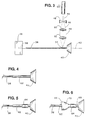
- the apparatus includes an elongate mandril 38 formed of stainless steel.
- the outside diameter of mandril 38 is approximately equal to the diameter of central lumen 32, so that the mandril receives catheter tubing 18 in sliding or slip fit fashion.
- the mandril is removably clamped within a jig or chuck 40, rotatable to rotate the mandril about a horizontal axis 42.
- a system for directing monochromatic energy onto the mandril includes a laser source 44 generating a laser beam 46 with a wavelength in the far infrared range.
- the laser is a CO 2 laser, in which case the wavelength of beam 46 is about 10.6 microns.
- the beam is directed through a concave-concave lens 48 which expands the beam, and then to a convex-convex lens 50 which collimates the beam.
- the collimated beam is directed through a convex-convex lens 52, which focuses the beam at a focal point or area 54 slightly radially outwardly of the mandril exterior surface.
- mandril guide 56 Near the free end of mandril 38 is a mandril guide 56 having an opening 58 slightly larger in diameter than the mandril.
- Guide 56 is movable axially of the mandril, between the location illustrated in which it is completely removed from mandril 38, and a support position in which the free end of the mandril is captured within opening 58, thus to stabilize the mandril rotation.
- the assembly of a balloon catheter 60 begins with the placement of a length of catheter tubing 62 onto the mandril, whereupon the catheter tubing is slid along the mandril to the right as viewed in Figure 3, until the distal end of the catheter tubing abuts jig 40 as shown in Figure 4.
- a relatively short (.030 inches (0.0762 cm)) length of heat shrink tubing 64 preferably constructed of a polyolefin, is positioned at least near the jig, surrounding the catheter tubing as shown in Figure 5.
- a dilatation balloon 66 is fitted onto and about the catheter tubing, and moved slidably until a distal shaft 68 of balloon 66 abuts jig 40.
- heat shrink tubing 64 surrounds distal shaft 68, with a proximal portion of the heat shrink tubing overlapping the distal end region of a distal cone 70. If desired, heat shrink tubing 64 can be of a sufficient length to abut jig 40 when in the position shown.
- laser source 44 and the accompanying optics are movable axially of the mandril relative to jig 40, to selectively align the laser system with respect to the jig.
- the laser system is positioned relative to the jig such that beam 46 is aligned on the intended center of the bond relative to the distal cone, i.e. at .025 inches (0.0635 cm) from the cone.
- laser source 44 is fired to generate beam 46 while mandril 38 is rotated.
- Lens 52 focuses beam 46 to position focal area 54 as illustrated in Figure 8, i.e. at the interface of catheter tubing 62 and distal shaft 68 of the dilatation balloon. Accordingly, the laser energy is concentrated along an annular bond site 72, defined by the rotation of the mandril, catheter tubing and balloon shaft relative to beam 46.
- Laser source 44 preferably is operated in the tem 00 mode, which results in a focal area having a Gaussian energy distribution, with maximum energy at the center of the focal area.
- the wavelength of the laser energy and the polymeric materials of dilatation balloon 66 and catheter tubing 62 are matched, in the sense that both the PET and the Hytrel polyester have a high absorptivity for energy at the selected wavelength of 10.6 microns.
- Polyesters exhibit a band of absorption ranging from about 7-11 microns, a range that encompasses the 10.6 micron wavelength of laser beam 46.
- the tendency in polymers to exhibit wavelength-selective absorption is observed not only in connection with infrared energy, but throughout the electromagnetic spectrum.
- heat shrink tubing 64 is removed.
- catheter balloons assembled according to the above described process can have substantially shorter distal tips and softer distal cones, for enhanced maneuverability in narrow, convoluted arteries.
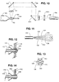
- Figure 9 illustrates a further step in the process, in which the distal bond is formed with an axial dimension larger than intended for the finished catheter, but with a controlled spacing from the distal cone.
- the steps discussed above are repeated without any substantial change.
- the completed balloon catheter is inserted by its distal tip into a cutting fixture 78 ( Figure 9) with the distal tip contained in an opening 80 through the fixture.
- a cutting fixture 78 Figure 9
- an excess length portion 82 of the distal tip extends beyond an end wall 84 of the fixture, and is conveniently cut away from the remainder of the catheter with a blade 86 movable along the end wall.
- Figure 10 illustrates an alternative means for concentrating the laser energy at an annular bond site.
- a length of catheter tubing 88, a dilatation balloon 90 and heat shrink tubing 92 are supported on an elongate stationary pin 94.
- a laser source 96 also stationary, generates a beam 98 of the preferred wavelength of 10.6 microns. Beam 98 is directed through a concave-concave diverging lens 100, and then through a convex-convex lens 102 to collimate the beam.
- the collimated beam is diverted by a series of planar reflectors at 104, 106 and 108, and finally through a convex-convex focusing lens 110, which locates the beam at the interface between catheter tubing 88 and dilatation balloon 90.
- planar reflectors 104, 106 and 108 and lens 110 are mounted integrally with respect to each other, but rotatable relative to pin 94.
- Figures 11-13 illustrate an alternative approach to forming the fusion bond, in which a length of catheter tubing 112, a dilatation balloon 114 and heat shrink tubing 116 are positioned within a bonding fixture 118 for directing multiple beams of laser energy onto the bond site.
- Fixture 118 includes a central opening 120 for receiving the tubing and balloon shaft, and further includes six radial openings for accommodating six optical fibers 122-132.
- the optical fibers are connected in common to a laser energy source 134.
- a single beam is effectively split into six identical beams, distributed uniformly about the bond area and slightly overlapping one another along the annular bond site to insure substantially even energy distribution.
- the near infrared wavelength is not as well matched to the absorption spectra of the polymeric materials forming the dilatation balloon and catheter tubing. Consequently, a coating of a dark ink or polymeric film is applied to the exterior of catheter tubing 112 at the bond site, and thus provides enhanced energy absorption at the interface, as is best seen at 136 in Figure 12.
- the system in Figures 11-13 forms satisfactory bonds without focusing optics, so long as sufficient power (less than 10 watts) is provided in laser source 134 and the optical fiber terminations are positioned sufficiently close to the dilatation balloon and tubing. If desired, however, the laser energy can be more effectively concentrated at the bond site with focusing optics, e.g. a planar-convex lens at the tip of each optical fiber near the bond site, as shown at 138 in connection with an optical fiber 140 in a fixture 142 similar to fixture 118. Lens 138 of course is selected to focus the beam at the interface between a length of catheter tubing 144 and a dilatation balloon 146 along the bond site.
- focusing optics e.g. a planar-convex lens at the tip of each optical fiber near the bond site
- One apparent advantage of the bonding approach shown in Figures 11-14 is the ability to maintain the fixture, beams, and polymeric components stationary as the bond is formed.
- a further advantage is that multiple beam fixtures can be fashioned to accommodate noncircular bonds, e.g. for catheter tubing having the cross section of an oval or ellipse in the bond region.
- proximal and distal bonds formed according to the present invention have been found to withstand substantial burst pressures, specifically in the range of about 425 pounds per square inch (2.930 megapascal). In fact, under testing the dilatation balloon itself tends to burst, prior to the failure of either fusion bond, even with the axial dimension of the distal fusion bond as low as .020 inches (0.0508 cm).
- the preferred embodiment balloon catheter 16 is of coaxial construction. It is to be understood that alternative catheter constructions, for example multilumen catheters, can be manufactured according to the process described above, within the scope of the present invention.
Landscapes
- Physics & Mathematics (AREA)
- Engineering & Computer Science (AREA)
- Mechanical Engineering (AREA)
- Health & Medical Sciences (AREA)
- Optics & Photonics (AREA)
- Toxicology (AREA)
- Electromagnetism (AREA)
- Life Sciences & Earth Sciences (AREA)
- Heart & Thoracic Surgery (AREA)
- Biophysics (AREA)
- General Health & Medical Sciences (AREA)
- Pulmonology (AREA)
- Anesthesiology (AREA)
- Biomedical Technology (AREA)
- Hematology (AREA)
- Animal Behavior & Ethology (AREA)
- Child & Adolescent Psychology (AREA)
- Public Health (AREA)
- Veterinary Medicine (AREA)
- Media Introduction/Drainage Providing Device (AREA)
- Materials For Medical Uses (AREA)
- Laser Surgery Devices (AREA)
- Lining Or Joining Of Plastics Or The Like (AREA)
Applications Claiming Priority (3)
| Application Number | Priority Date | Filing Date | Title |
|---|---|---|---|
| US800201 | 1991-11-29 | ||
| US07/800,201 US5267959A (en) | 1991-11-29 | 1991-11-29 | Laser bonding of angioplasty balloon catheters |
| EP92920127A EP0618861B1 (de) | 1991-11-29 | 1992-09-04 | Laserschweissen von angioplastie ballonkathetern |
Related Parent Applications (1)
| Application Number | Title | Priority Date | Filing Date |
|---|---|---|---|
| EP92920127.5 Division | 1993-06-21 |
Publications (3)
| Publication Number | Publication Date |
|---|---|
| EP0839634A2 true EP0839634A2 (de) | 1998-05-06 |
| EP0839634A3 EP0839634A3 (de) | 2001-02-14 |
| EP0839634B1 EP0839634B1 (de) | 2003-11-05 |
Family
ID=25177744
Family Applications (2)
| Application Number | Title | Priority Date | Filing Date |
|---|---|---|---|
| EP92920127A Expired - Lifetime EP0618861B1 (de) | 1991-11-29 | 1992-09-04 | Laserschweissen von angioplastie ballonkathetern |
| EP98200064A Expired - Lifetime EP0839634B1 (de) | 1991-11-29 | 1992-09-04 | Laserschweissen von Angioplastie-Ballonkathetern |
Family Applications Before (1)
| Application Number | Title | Priority Date | Filing Date |
|---|---|---|---|
| EP92920127A Expired - Lifetime EP0618861B1 (de) | 1991-11-29 | 1992-09-04 | Laserschweissen von angioplastie ballonkathetern |
Country Status (9)
| Country | Link |
|---|---|
| US (2) | US5267959A (de) |
| EP (2) | EP0618861B1 (de) |
| JP (3) | JP2511643B2 (de) |
| AT (2) | ATE187120T1 (de) |
| AU (1) | AU659494B2 (de) |
| CA (1) | CA2121495C (de) |
| DE (3) | DE69230377T2 (de) |
| ES (1) | ES2205372T3 (de) |
| WO (1) | WO1993010961A1 (de) |
Cited By (11)
| Publication number | Priority date | Publication date | Assignee | Title |
|---|---|---|---|---|
| WO1999002330A1 (de) * | 1997-07-11 | 1999-01-21 | Iwka Pacunion Gmbh | Verfahren und vorrichtung zum verschweissen der enden von rohrartigen behältern, insbesondere von tuben |
| FR2812372A1 (fr) * | 2000-07-26 | 2002-02-01 | Coutier Moulage Gen Ind | Procede de connexion de deux pieces tubulaires realisees en matieres plastiques |
| EP1048439A3 (de) * | 1999-04-29 | 2002-03-06 | BIELOMATIK LEUZE GmbH + Co. | Verfahren und Vorrichtung zum Schweissen |
| WO2003008009A1 (en) * | 2001-07-18 | 2003-01-30 | Scimed Life Systems, Inc. | Light emitting markers for use with substrates |
| WO2003011574A1 (de) * | 2001-07-28 | 2003-02-13 | Boehringer Ingelheim Pharma Gmbh & Co. Kg | Verfahren zum stoffschlüssigen verschweissen von medizinischen kapseln für die inhalation und apparat zum verschweissen |
| WO2004007180A1 (en) * | 2002-07-12 | 2004-01-22 | E. I. Du Pont De Nemours And Company | A process for laser welding together articles of polyester resin compositions and related products |
| EP1403030A1 (de) * | 2002-09-27 | 2004-03-31 | Degussa AG | Rohrverbindung |
| US6949154B2 (en) | 2001-07-28 | 2005-09-27 | Boehringer Ingelheim Pharma Kg | Method and apparatus for sealing medicinal capsules |
| WO2005080067A3 (en) * | 2004-02-19 | 2005-11-10 | Baxter Int | Solventless plastic bonding of medical devices and container components through infrared heating |
| US7279521B2 (en) | 1999-11-10 | 2007-10-09 | Foster Corporation | Nylon nanocomposites |
| EP2301620A1 (de) * | 2002-01-31 | 2011-03-30 | Baxter International Inc. | Laserschweissapparat zum Verbinden der Enden von zwei flexiblen Röhren |
Families Citing this family (116)
| Publication number | Priority date | Publication date | Assignee | Title |
|---|---|---|---|---|
| US5267959A (en) | 1991-11-29 | 1993-12-07 | Schneider, Inc. | Laser bonding of angioplasty balloon catheters |
| US6896842B1 (en) | 1993-10-01 | 2005-05-24 | Boston Scientific Corporation | Medical device balloons containing thermoplastic elastomers |
| JP3577082B2 (ja) | 1993-10-01 | 2004-10-13 | ボストン・サイエンティフィック・コーポレーション | 熱可塑性エラストマーから成る医療装置用バルーン |
| ATE184799T1 (de) * | 1993-10-27 | 1999-10-15 | Schneider Europ Gmbh | Eingriffskatheter |
| US6659977B2 (en) | 1993-10-27 | 2003-12-09 | Schneider (Europe) A.G. | Multilayer interventional catheter |
| US5961765A (en) * | 1994-09-20 | 1999-10-05 | Schneider (Europe) A. G. | Method of making a catheter |
| GB2286147B (en) * | 1994-02-08 | 1998-01-07 | Uponor Aldyl Ltd | Method of joining elongate hollow members |
| US5415636A (en) * | 1994-04-13 | 1995-05-16 | Schneider (Usa) Inc | Dilation-drug delivery catheter |
| US5549557A (en) * | 1994-08-05 | 1996-08-27 | Medtronic, Inc. | Catheter balloon proximal heat bond on extended shaft |
| US5514092A (en) * | 1994-08-08 | 1996-05-07 | Schneider (Usa) Inc. | Drug delivery and dilatation-drug delivery catheters in a rapid exchange configuration |
| US5667493A (en) * | 1994-12-30 | 1997-09-16 | Janacek; Jaroslav | Dilation catheter |
| ATE197760T1 (de) | 1995-06-29 | 2000-12-15 | Schneider Europ Gmbh | Medizinisches gerät für druckmessung in einem blutgefäss |
| US5865801A (en) * | 1995-07-18 | 1999-02-02 | Houser; Russell A. | Multiple compartmented balloon catheter with external pressure sensing |
| US5733301A (en) * | 1996-01-11 | 1998-03-31 | Schneider (Usa) Inc. | Laser ablation of angioplasty catheters and balloons |
| DE69732836T2 (de) * | 1996-01-16 | 2006-04-13 | Advanced Cardiovascular Systems, Inc., Santa Clara | Gleitfähiger leicht haftbarer katheterschaft |
| US6217547B1 (en) * | 1996-01-16 | 2001-04-17 | Advanced Cardiovascular Systems, Inc. | Lubricous and readily bondable catheter shaft |
| DE69625329T3 (de) | 1996-04-26 | 2012-05-10 | Schneider (Europe) Gmbh | Eingriffkatheter |
| GB9616267D0 (en) * | 1996-08-02 | 1996-09-11 | Ranier Ltd | Balloon catheter |
| US7252650B1 (en) | 1996-08-02 | 2007-08-07 | Ranier Limited | Balloon catheter |
| EP0835673A3 (de) | 1996-10-10 | 1998-09-23 | Schneider (Usa) Inc. | Katheter für Gewebedilatation und Arzneimittelverabreichung |
| US5876376A (en) * | 1996-12-09 | 1999-03-02 | Medtronic, Inc | Catheter balloon bonding stopper |
| US6165166A (en) * | 1997-04-25 | 2000-12-26 | Schneider (Usa) Inc. | Trilayer, extruded medical tubing and medical devices incorporating such tubing |
| US6139525A (en) | 1997-07-08 | 2000-10-31 | Advanced Cardiovascular Systems, Inc. | Fusion bonding of catheter components |
| DE19750263A1 (de) * | 1997-11-13 | 1999-05-20 | Iwk Verpackungstechnik Gmbh | Verfahren und Vorrichtung zum Verschließen einer Kunststoff-Tube in einer Tubenfüllmaschine |
| NL1008178C2 (nl) * | 1998-02-02 | 1999-08-04 | Cordis Europ | Katheter en werkwijze voor het vervaardigen hiervan. |
| US20020007145A1 (en) | 1998-10-23 | 2002-01-17 | Timothy Stivland | Catheter having improved bonding region |
| US20030029040A1 (en) | 1999-03-08 | 2003-02-13 | Cesaroni Anthony Joseph | Laser bonding of heat exchanger tubes |
| DE19919428C2 (de) | 1999-04-28 | 2001-12-06 | Tyco Electronics Logistics Ag | Kunststoff-Ferrule für einen Lichtwellenleiter und Verfahren zum Befestigen einer Ferrule an einem Lichtwellenleiter |
| DE19933279A1 (de) * | 1999-07-14 | 2001-03-01 | Biotronik Mess & Therapieg | Polymerwerkstoff |
| US6605031B1 (en) | 1999-09-22 | 2003-08-12 | Advanced Cardiovascular Systems, Inc. | Stepped centering balloon for optimal radiation delivery |
| US6582417B1 (en) * | 1999-09-22 | 2003-06-24 | Advanced Cardiovascular Systems, Inc. | Methods and apparatuses for radiation treatment |
| US6746424B2 (en) * | 1999-12-11 | 2004-06-08 | Advanced Cardiovascular Systems, Inc. | Shaftless balloon |
| US6368301B1 (en) | 1999-12-21 | 2002-04-09 | Advanced Cardiovascular Systems, Inc. | Catheter having a soft distal tip |
| US6994687B1 (en) * | 2000-01-19 | 2006-02-07 | Cordis Neurovascular, Inc. | Inflatable balloon catheter with purge mechanism and method |
| US6723113B1 (en) * | 2000-01-19 | 2004-04-20 | Cordis Neurovascular, Inc. | Inflatable balloon catheter seal and method |
| US7163504B1 (en) | 2000-02-16 | 2007-01-16 | Advanced Cardiovascular Systems, Inc. | Multi-lumen fluted balloon radiation centering catheter |
| US7994449B2 (en) * | 2000-02-16 | 2011-08-09 | Advanced Cardiovascular Systems, Inc. | Square-wave laser bonding |
| US6548010B1 (en) * | 2000-03-23 | 2003-04-15 | Scimed Life Systems, Inc. | Transition region for an intravascular catheter |
| US6585687B1 (en) | 2000-03-27 | 2003-07-01 | Cordis Corporation | Inflatable balloon catheter body construction |
| US6860960B1 (en) * | 2000-09-05 | 2005-03-01 | Scimed Life Systems, Inc. | Method of applying a laser beam around the circumference of a catheter |
| US6461326B1 (en) | 2000-10-26 | 2002-10-08 | Scimed Life Systems, Inc. | Fluorescent dyed adhesive for bonding various components in a medical device |
| EP1341668A2 (de) * | 2000-11-10 | 2003-09-10 | Gentex Corporation | Durchsichtige farbstoffe zum laser-durchstrahlschweissen |
| US6893456B2 (en) * | 2000-12-22 | 2005-05-17 | Advanced Cardiovascular Systems, Inc. | Catheter and method for making the same |
| US6740191B2 (en) | 2001-02-22 | 2004-05-25 | Medtronic Ave, Inc. | Through-transmission welding of catheter components |
| US6893416B2 (en) | 2001-06-12 | 2005-05-17 | Medtronic Vascular, Inc. | Tip seal tip attach |
| JP2003019205A (ja) * | 2001-07-09 | 2003-01-21 | Asahi Intecc Co Ltd | カテーテルチューブおよびその製造方法 |
| US6692461B2 (en) | 2001-08-07 | 2004-02-17 | Advanced Cardiovascular Systems, Inc. | Catheter tip |
| US6752893B2 (en) * | 2001-09-28 | 2004-06-22 | Gentex Corporation | Rimless spectacles and method for making the same |
| US6918920B1 (en) * | 2001-11-01 | 2005-07-19 | Advanced Cardiovascular Systems, Inc. | Catheter having an improved distal tip |
| CN100389019C (zh) * | 2001-11-07 | 2008-05-21 | 黑﨑晏夫 | 热塑性树脂铸件的焊接方法 |
| US6923787B2 (en) * | 2001-12-20 | 2005-08-02 | Scimed Life Systems, Inc. | Catheter having an improved balloon-to-catheter bond |
| US7914486B2 (en) * | 2001-12-20 | 2011-03-29 | Boston Scientific Scimed, Inc. | Catheter having an improved balloon-to-catheter bond |
| US7201963B2 (en) * | 2002-01-15 | 2007-04-10 | Gentex Corporation | Pre-processed workpiece having a surface deposition of absorber dye rendering the workpiece weld-enabled |
| US20030135231A1 (en) * | 2002-01-17 | 2003-07-17 | Goodin Richardf L. | Catheter bond configuration |
| US6858104B2 (en) * | 2002-01-28 | 2005-02-22 | Scimed Life Systems, Inc. | Apparatus and method for closed-loop control of laser welder for welding polymeric catheter components |
| US7785340B2 (en) * | 2002-02-04 | 2010-08-31 | Boston Scientific Scimed, Inc. | Bonding sleeve for medical device |
| US20030201059A1 (en) * | 2002-04-24 | 2003-10-30 | Holman Thomas J. | Selective manipulation of material for medical devices and methods and devices made therefrom |
| US6858083B2 (en) * | 2002-06-05 | 2005-02-22 | Scimed Lifesystems, Inc. | Apparatus and method for closed-loop control of RF generator for welding polymeric catheter components |
| US20040086674A1 (en) * | 2002-11-01 | 2004-05-06 | Holman Thomas J. | Laser sintering process and devices made therefrom |
| DE50209306D1 (de) | 2002-12-31 | 2007-03-08 | Abbott Lab Vascular Entpr Ltd | Katheter mit einem flexibleren Bereich zwischen Schaft und Spitze sowie Verfahren zu seiner Herstellung |
| ATE291458T1 (de) * | 2002-12-31 | 2005-04-15 | Abbott Lab Vascular Entpr Ltd | Verfahren zum verbinden eines ballons mit einem schaft eines ballonkatheters |
| US7331933B2 (en) * | 2002-12-31 | 2008-02-19 | Advanced Cardiovascular Systems, Inc. | Balloon catheter with a compression member for balloon bonding |
| US20080269846A1 (en) * | 2003-03-14 | 2008-10-30 | Light Sciences Oncology, Inc. | Device for treatment of blood vessels using light |
| WO2004082736A2 (en) * | 2003-03-14 | 2004-09-30 | Light Sciences Corporation | Light generating device to intravascular use |
| US10376711B2 (en) | 2003-03-14 | 2019-08-13 | Light Sciences Oncology Inc. | Light generating guide wire for intravascular use |
| CN2885311Y (zh) | 2006-01-18 | 2007-04-04 | 郑成福 | 经尿道光动力疗法前列腺治疗仪 |
| US7261936B2 (en) * | 2003-05-28 | 2007-08-28 | Albany International Corp. | Synthetic blown insulation |
| CA2537235A1 (en) * | 2003-07-09 | 2005-01-27 | Light Sciences Corporation | Device for distal protection and treatment of blood vessels |
| EP1698446B1 (de) * | 2003-12-26 | 2014-09-17 | Kuraray Co., Ltd., Kurashiki Plant | Verfahren zur herstellung eines röhrenförmigen artikels |
| US7722733B2 (en) * | 2004-03-29 | 2010-05-25 | Baxter International Inc. | Method for sterile connection of tubing |
| US20050228428A1 (en) * | 2004-04-07 | 2005-10-13 | Afsar Ali | Balloon catheters and methods for manufacturing balloons for balloon catheters |
| US7345256B2 (en) * | 2004-04-08 | 2008-03-18 | Ziyun Chen | Methods and apparatus for delivering laser energy for joining parts |
| US7815624B2 (en) * | 2004-05-18 | 2010-10-19 | Boston Scientific Scimed, Inc. | Medical devices and methods of making the same |
| US20080135170A1 (en) * | 2004-05-21 | 2008-06-12 | Fugui He | Systems and Methods for Laser Bonding Catheter Components |
| WO2005113049A1 (en) * | 2004-05-21 | 2005-12-01 | Cordis Corporation | Systems and methods for laser bonding catheter components |
| US7785439B2 (en) * | 2004-09-29 | 2010-08-31 | Abbott Laboratories Vascular Enterprises Limited | Method for connecting a catheter balloon with a catheter shaft of a balloon catheter |
| US7261850B2 (en) * | 2004-06-30 | 2007-08-28 | Cordis Corporation | Methods of making balloon catheter tip |
| US7820936B2 (en) * | 2004-07-02 | 2010-10-26 | Boston Scientific Scimed, Inc. | Method and apparatus for controlling and adjusting the intensity profile of a laser beam employed in a laser welder for welding polymeric and metallic components |
| US7820937B2 (en) * | 2004-10-27 | 2010-10-26 | Boston Scientific Scimed, Inc. | Method of applying one or more electromagnetic beams to form a fusion bond on a workpiece such as a medical device |
| FR2878185B1 (fr) * | 2004-11-22 | 2008-11-07 | Sidel Sas | Procede de fabrication de recipients comprenant une etape de chauffe au moyen d'un faisceau de rayonnement electromagnetique coherent |
| US8298179B2 (en) * | 2004-12-22 | 2012-10-30 | Boston Scientific Scimed, Inc. | Catheter assembly with tapered joints and method of manufacture |
| US8202245B2 (en) * | 2005-01-26 | 2012-06-19 | Boston Scientific Scimed, Inc. | Medical devices and methods of making the same |
| CA2538761A1 (en) * | 2005-03-08 | 2006-09-08 | Anthony Joseph Cesaroni | Method for sealing heat exchanger tubes |
| US9352133B2 (en) | 2005-06-09 | 2016-05-31 | Boston Scientific Scimed, Inc. | Balloon catheters with increased column strength |
| EP1917062B1 (de) * | 2005-08-19 | 2009-10-21 | Abbott Laboratories Vascular Enterprises Limited | Verfahren zur herstellung eines ballons eines ballonkatheters und ballon |
| CN1992461B (zh) * | 2005-12-30 | 2010-05-05 | 鸿富锦精密工业(深圳)有限公司 | 电线绝缘层切割装置 |
| US7678223B2 (en) * | 2006-04-17 | 2010-03-16 | Boston Scientific Scimed, Inc. | Catheter having a multi-section tubular member and method of making the same |
| JP4855145B2 (ja) * | 2006-05-24 | 2012-01-18 | テルモ株式会社 | 医療器の製造方法 |
| US20080023453A1 (en) * | 2006-07-17 | 2008-01-31 | Zhang Ping Y | Methods and apparatus for delivering laser energy for joining parts |
| US8043296B2 (en) * | 2006-08-25 | 2011-10-25 | Kyphon Sarl | Apparatus and methods for use of expandable members in surgical applications |
| US8382709B2 (en) * | 2006-09-25 | 2013-02-26 | Boston Scientific Scimed, Inc. | Designs for balloon welds |
| FR2906503A1 (fr) * | 2006-09-28 | 2008-04-04 | Inergy Automotive Systems Res | Dispositif de fixation d'un film sur un reservoir en matiere plastique |
| US7857786B2 (en) * | 2006-11-03 | 2010-12-28 | Cook Incorporated | Balloon catheter having improved balloon folding capability |
| US8845581B2 (en) * | 2006-11-14 | 2014-09-30 | Boston Scientific Scimed, Inc. | Medical balloon deflation |
| FR2913210B1 (fr) * | 2007-03-02 | 2009-05-29 | Sidel Participations | Perfectionnements a la chauffe des matieres plastiques par rayonnement infrarouge |
| US7549975B2 (en) * | 2007-04-20 | 2009-06-23 | Abbott Cardiovascular Systems, Inc. | Catheter having a readily bondable multilayer soft tip |
| FR2917005B1 (fr) * | 2007-06-11 | 2009-08-28 | Sidel Participations | Installation de chauffage des corps de preformes pour le soufflage de recipients |
| US8088256B2 (en) * | 2007-09-05 | 2012-01-03 | Albany International Corp. | Process for producing papermaker's and industrial fabric seam and seam produced by that method |
| ES2819283T3 (es) * | 2007-09-05 | 2021-04-15 | Albany Int Corp | Proceso para la producción de costura para tela de papelería e industrial y costura producida por ese método |
| US7794555B2 (en) * | 2007-09-05 | 2010-09-14 | Albany International Corp. | Formation of a fabric seam by ultrasonic gap welding of a flat woven fabric |
| US7897018B2 (en) * | 2007-09-05 | 2011-03-01 | Albany International Corp. | Process for producing papermaker's and industrial fabrics |
| US20090069748A1 (en) * | 2007-09-12 | 2009-03-12 | Cook Incorporated | Pushable balloon catheter assembly |
| FR2929549B1 (fr) * | 2008-04-08 | 2012-04-20 | Monnier Marc Le | Procede de fabrication d'une structure alveolaire,structure alveolaire et installation correspondantes |
| US8216498B2 (en) | 2008-09-10 | 2012-07-10 | Boston Scientific Scimed, Inc. | Catheter having a coextruded fluoropolymer layer |
| JP4845158B2 (ja) | 2010-04-01 | 2011-12-28 | 精電舎電子工業株式会社 | バルーンカテーテル製造装置、バルーンカテーテル製造方法、カテーテル接続装置、及びカテーテルの接続方法 |
| WO2011155016A1 (ja) * | 2010-06-07 | 2011-12-15 | 浜松ホトニクス株式会社 | 樹脂溶着方法 |
| US9554840B2 (en) | 2011-04-08 | 2017-01-31 | Kyphon SÀRL | Low cost low profile inflatable bone tamp |
| JP5668242B2 (ja) * | 2011-09-30 | 2015-02-12 | 精電舎電子工業株式会社 | バルーンカテーテル製造装置、バルーンカテーテル製造方法、カテーテル接続装置、カテーテルの接続方法 |
| US20160023402A1 (en) * | 2014-07-28 | 2016-01-28 | Cook Medical Technologies Llc | Plastic welding system and method of making medical device |
| EP3374152B1 (de) * | 2015-11-13 | 2020-09-30 | Airopack Technology Group B.V. | System und verfahren zum zusammenbau einer druckeinheit mit einem behälter |
| US10794523B2 (en) | 2015-12-14 | 2020-10-06 | Wilmarc Holdings, Llc | Laser induced sealing of concentrically layered materials |
| US11191930B2 (en) * | 2016-04-12 | 2021-12-07 | Boston Scientific Scimed, Inc. | Medical balloon |
| US11051407B2 (en) | 2018-10-23 | 2021-06-29 | International Business Machines Corporation | Facilitating filling a plated through-hole of a circuit board with solder |
| US11992635B2 (en) | 2019-02-25 | 2024-05-28 | Medtronic Vascular, Inc. | Medical balloon assembly |
| US10729016B1 (en) | 2019-03-13 | 2020-07-28 | International Business Machines Corporation | Shape-memory alloy connector for plated through-hole |
| CN116419837A (zh) * | 2020-10-23 | 2023-07-11 | 美敦力公司 | 使用纤维激光器的用于医疗装置的部件的焊接方法 |
Family Cites Families (28)
| Publication number | Priority date | Publication date | Assignee | Title |
|---|---|---|---|---|
| US3560291A (en) * | 1964-03-27 | 1971-02-02 | Mobil Oil Corp | Bonding thermoplastic resin films by means of radiation from a laser source |
| AT289377B (de) * | 1965-08-20 | 1971-04-26 | Windmoeller & Hoelscher | Strahlungsschweißeinrichtung |
| DE1479239A1 (de) * | 1965-12-27 | 1969-06-04 | Hoechst Ag | Verfahren zum Verbinden von Gebilden aus thermoplastischen Kunststoffen unter Waermeeinfluss |
| US3528867A (en) * | 1966-08-15 | 1970-09-15 | Heller William C Jun | Method for selective heat sealing or joining of materials |
| US3528869A (en) * | 1968-02-28 | 1970-09-15 | Davol Inc | Manufacture of plastic catheter |
| BE792903A (nl) * | 1971-12-30 | 1973-06-18 | American Can Co | Laserstraal-lassen van kunststoffen buizen |
| US3953706A (en) * | 1974-03-29 | 1976-04-27 | Martin Marietta Corporation | Laser bent beam controlled dwell wire stripper |
| US3974016A (en) * | 1974-11-04 | 1976-08-10 | Bell Telephone Laboratories, Incorporated | Bonding of thermoplastic coated cylinders |
| US3989778A (en) * | 1975-12-17 | 1976-11-02 | W. R. Grace & Co. | Method of heat sealing thermoplastic sheets together using a split laser beam |
| US4069080A (en) * | 1976-06-11 | 1978-01-17 | W. R. Grace & Co. | Method and apparatus of bonding superposed sheets of polymeric material in a linear weld |
| US4251305A (en) * | 1978-11-01 | 1981-02-17 | Baxter Travenol Laboratories, Inc. | Method of radiant heat sealing of a balloon onto a catheter employing tinted shrink tubing |
| US4276874A (en) * | 1978-11-15 | 1981-07-07 | Datascope Corp. | Elongatable balloon catheter |
| SE434480B (sv) * | 1982-02-18 | 1984-07-30 | Optik Innovation Ab Oiab | Anordning for bearbetning av ett utvendigt omkretsomrade av en artikel medelst stralningsenergi, speciellt for utvendig forsegling av en rorformig termoplastfolie medelst en laserstrale |
| JPS58166168A (ja) * | 1982-03-29 | 1983-10-01 | Toshiba Corp | ベロ−ズ |
| US4550238A (en) * | 1982-11-05 | 1985-10-29 | Warner-Lambert Company | Apparatus and method for sealing capsules |
| DE3325930C2 (de) * | 1983-07-19 | 1986-07-03 | Gebr. Bindler Maschinenfabrik GmbH & Co KG, 5275 Bergneustadt | Vorrichtung zum Erwärmen miteinander zu verbindender, abgegrenzter Bereiche eines mehrteiligen Gegenstandes |
| JPS61103688A (ja) * | 1984-10-26 | 1986-05-22 | Fujitsu Ltd | レ−ザと光フアイバを用いた加工方法 |
| US4777951A (en) * | 1986-09-19 | 1988-10-18 | Mansfield Scientific, Inc. | Procedure and catheter instrument for treating patients for aortic stenosis |
| US4733047A (en) * | 1987-02-20 | 1988-03-22 | American Telephone And Telegraph Company | Spot welding technique |
| US4958634A (en) * | 1987-05-06 | 1990-09-25 | Jang G David | Limacon geometry balloon angioplasty catheter systems and method of making same |
| US4963313A (en) * | 1987-11-30 | 1990-10-16 | Boston Scientific Corporation | Balloon catheter |
| US4950239A (en) * | 1988-08-09 | 1990-08-21 | Worldwide Medical Plastics Inc. | Angioplasty balloons and balloon catheters |
| US5108415A (en) * | 1988-10-04 | 1992-04-28 | Cordis Corporation | Balloons for medical devices and fabrication thereof |
| JPH084628B2 (ja) * | 1988-10-20 | 1996-01-24 | テルモ株式会社 | 拡張体付カテーテル |
| US4941877A (en) * | 1989-01-26 | 1990-07-17 | Cordis Corporation | Balloon catheter |
| NL8901257A (nl) * | 1989-05-19 | 1990-12-17 | Leeuwarder Papier | Werkwijze voor het aanbrengen van verzwakkingslijnen in resp. het graveren van kunststofmateriaal, in het bijzonder verpakkingsmateriaal. |
| US5279693A (en) * | 1990-05-09 | 1994-01-18 | Lps Industries, Inc. | Welding thermoplastic material with a laser |
| US5267959A (en) | 1991-11-29 | 1993-12-07 | Schneider, Inc. | Laser bonding of angioplasty balloon catheters |
-
1991
- 1991-11-29 US US07/800,201 patent/US5267959A/en not_active Expired - Lifetime
-
1992
- 1992-09-04 CA CA002121495A patent/CA2121495C/en not_active Expired - Fee Related
- 1992-09-04 EP EP92920127A patent/EP0618861B1/de not_active Expired - Lifetime
- 1992-09-04 AT AT92920127T patent/ATE187120T1/de not_active IP Right Cessation
- 1992-09-04 ES ES98200064T patent/ES2205372T3/es not_active Expired - Lifetime
- 1992-09-04 DE DE69230377T patent/DE69230377T2/de not_active Expired - Lifetime
- 1992-09-04 AT AT98200064T patent/ATE253447T1/de not_active IP Right Cessation
- 1992-09-04 JP JP51007793A patent/JP2511643B2/ja not_active Expired - Lifetime
- 1992-09-04 WO PCT/US1992/007340 patent/WO1993010961A1/en not_active Ceased
- 1992-09-04 AU AU25729/92A patent/AU659494B2/en not_active Expired
- 1992-09-04 EP EP98200064A patent/EP0839634B1/de not_active Expired - Lifetime
- 1992-09-04 DE DE1992633247 patent/DE69233247T2/de not_active Expired - Lifetime
- 1992-09-04 DE DE9290143U patent/DE9290143U1/de not_active Expired - Lifetime
-
1994
- 1994-09-12 US US08/304,413 patent/US5501759A/en not_active Expired - Lifetime
-
1995
- 1995-11-30 JP JP31188495A patent/JP2840575B2/ja not_active Expired - Lifetime
-
1998
- 1998-05-22 JP JP14140698A patent/JP3234809B2/ja not_active Expired - Lifetime
Cited By (14)
| Publication number | Priority date | Publication date | Assignee | Title |
|---|---|---|---|---|
| US6417483B1 (en) * | 1997-07-11 | 2002-07-09 | Iwka Pacunion Gmbh | Method and device for soldering the ends of tubular containers, specially tubes |
| WO1999002330A1 (de) * | 1997-07-11 | 1999-01-21 | Iwka Pacunion Gmbh | Verfahren und vorrichtung zum verschweissen der enden von rohrartigen behältern, insbesondere von tuben |
| EP1048439A3 (de) * | 1999-04-29 | 2002-03-06 | BIELOMATIK LEUZE GmbH + Co. | Verfahren und Vorrichtung zum Schweissen |
| US7279521B2 (en) | 1999-11-10 | 2007-10-09 | Foster Corporation | Nylon nanocomposites |
| FR2812372A1 (fr) * | 2000-07-26 | 2002-02-01 | Coutier Moulage Gen Ind | Procede de connexion de deux pieces tubulaires realisees en matieres plastiques |
| US6764710B2 (en) | 2001-07-18 | 2004-07-20 | Scimed Life Systems, Inc. | Light emitting markers for use with substrates |
| WO2003008009A1 (en) * | 2001-07-18 | 2003-01-30 | Scimed Life Systems, Inc. | Light emitting markers for use with substrates |
| US6949154B2 (en) | 2001-07-28 | 2005-09-27 | Boehringer Ingelheim Pharma Kg | Method and apparatus for sealing medicinal capsules |
| EP1792705A1 (de) * | 2001-07-28 | 2007-06-06 | Boehringer Ingelheim Pharma GmbH & Co. KG | Verfahren zum stoffschlüssigen Verschweissen von medizinischen Kapseln für die Inhalation und Apparat zum Verschweissen |
| WO2003011574A1 (de) * | 2001-07-28 | 2003-02-13 | Boehringer Ingelheim Pharma Gmbh & Co. Kg | Verfahren zum stoffschlüssigen verschweissen von medizinischen kapseln für die inhalation und apparat zum verschweissen |
| EP2301620A1 (de) * | 2002-01-31 | 2011-03-30 | Baxter International Inc. | Laserschweissapparat zum Verbinden der Enden von zwei flexiblen Röhren |
| WO2004007180A1 (en) * | 2002-07-12 | 2004-01-22 | E. I. Du Pont De Nemours And Company | A process for laser welding together articles of polyester resin compositions and related products |
| EP1403030A1 (de) * | 2002-09-27 | 2004-03-31 | Degussa AG | Rohrverbindung |
| WO2005080067A3 (en) * | 2004-02-19 | 2005-11-10 | Baxter Int | Solventless plastic bonding of medical devices and container components through infrared heating |
Also Published As
| Publication number | Publication date |
|---|---|
| EP0618861A1 (de) | 1994-10-12 |
| DE69233247D1 (de) | 2003-12-11 |
| US5501759A (en) | 1996-03-26 |
| EP0618861B1 (de) | 1999-12-01 |
| EP0839634A3 (de) | 2001-02-14 |
| CA2121495C (en) | 1998-04-14 |
| AU2572992A (en) | 1993-06-28 |
| JPH09182796A (ja) | 1997-07-15 |
| DE69233247T2 (de) | 2004-08-26 |
| JP2511643B2 (ja) | 1996-07-03 |
| DE9290143U1 (de) | 1994-07-28 |
| JP2840575B2 (ja) | 1998-12-24 |
| EP0839634B1 (de) | 2003-11-05 |
| ES2205372T3 (es) | 2004-05-01 |
| ATE253447T1 (de) | 2003-11-15 |
| ATE187120T1 (de) | 1999-12-15 |
| JPH10323393A (ja) | 1998-12-08 |
| JPH06510715A (ja) | 1994-12-01 |
| AU659494B2 (en) | 1995-05-18 |
| DE69230377T2 (de) | 2000-07-27 |
| CA2121495A1 (en) | 1993-06-10 |
| DE69230377D1 (de) | 2000-01-05 |
| US5267959A (en) | 1993-12-07 |
| WO1993010961A1 (en) | 1993-06-10 |
| JP3234809B2 (ja) | 2001-12-04 |
Similar Documents
| Publication | Publication Date | Title |
|---|---|---|
| EP0618861B1 (de) | Laserschweissen von angioplastie ballonkathetern | |
| US6860960B1 (en) | Method of applying a laser beam around the circumference of a catheter | |
| EP1234595B1 (de) | Transmissionsschweissen von Katheterkomponenten | |
| US20050119616A1 (en) | Catheter bond configuration | |
| US7820937B2 (en) | Method of applying one or more electromagnetic beams to form a fusion bond on a workpiece such as a medical device | |
| WO2024256124A1 (en) | Apparatus for laser welding and respective method | |
| US7994449B2 (en) | Square-wave laser bonding | |
| US20250345556A1 (en) | Method for manufacturing catheter | |
| JP4192180B2 (ja) | カテーテルの製造方法 | |
| Flanagan | Laser welding of balloon catheters | |
| JP2511643C (de) |
Legal Events
| Date | Code | Title | Description |
|---|---|---|---|
| PUAI | Public reference made under article 153(3) epc to a published international application that has entered the european phase |
Free format text: ORIGINAL CODE: 0009012 |
|
| 17P | Request for examination filed |
Effective date: 19980113 |
|
| AC | Divisional application: reference to earlier application |
Ref document number: 618861 Country of ref document: EP |
|
| AK | Designated contracting states |
Kind code of ref document: A2 Designated state(s): AT BE CH DE DK ES FR GB GR IT LI LU NL SE |
|
| PUAL | Search report despatched |
Free format text: ORIGINAL CODE: 0009013 |
|
| AK | Designated contracting states |
Kind code of ref document: A3 Designated state(s): AT BE CH DE DK ES FR GB GR IT LI LU NL SE |
|
| 17Q | First examination report despatched |
Effective date: 20011206 |
|
| GRAH | Despatch of communication of intention to grant a patent |
Free format text: ORIGINAL CODE: EPIDOS IGRA |
|
| GRAS | Grant fee paid |
Free format text: ORIGINAL CODE: EPIDOSNIGR3 |
|
| GRAA | (expected) grant |
Free format text: ORIGINAL CODE: 0009210 |
|
| AC | Divisional application: reference to earlier application |
Ref document number: 0618861 Country of ref document: EP Kind code of ref document: P |
|
| AK | Designated contracting states |
Kind code of ref document: B1 Designated state(s): AT BE CH DE DK ES FR GB GR IT LI LU NL SE |
|
| PG25 | Lapsed in a contracting state [announced via postgrant information from national office to epo] |
Ref country code: LI Free format text: LAPSE BECAUSE OF FAILURE TO SUBMIT A TRANSLATION OF THE DESCRIPTION OR TO PAY THE FEE WITHIN THE PRESCRIBED TIME-LIMIT Effective date: 20031105 Ref country code: CH Free format text: LAPSE BECAUSE OF FAILURE TO SUBMIT A TRANSLATION OF THE DESCRIPTION OR TO PAY THE FEE WITHIN THE PRESCRIBED TIME-LIMIT Effective date: 20031105 Ref country code: BE Free format text: LAPSE BECAUSE OF FAILURE TO SUBMIT A TRANSLATION OF THE DESCRIPTION OR TO PAY THE FEE WITHIN THE PRESCRIBED TIME-LIMIT Effective date: 20031105 Ref country code: AT Free format text: LAPSE BECAUSE OF FAILURE TO SUBMIT A TRANSLATION OF THE DESCRIPTION OR TO PAY THE FEE WITHIN THE PRESCRIBED TIME-LIMIT Effective date: 20031105 |
|
| REG | Reference to a national code |
Ref country code: GB Ref legal event code: FG4D |
|
| REG | Reference to a national code |
Ref country code: CH Ref legal event code: EP |
|
| REF | Corresponds to: |
Ref document number: 69233247 Country of ref document: DE Date of ref document: 20031211 Kind code of ref document: P |
|
| PG25 | Lapsed in a contracting state [announced via postgrant information from national office to epo] |
Ref country code: SE Free format text: LAPSE BECAUSE OF FAILURE TO SUBMIT A TRANSLATION OF THE DESCRIPTION OR TO PAY THE FEE WITHIN THE PRESCRIBED TIME-LIMIT Effective date: 20040205 Ref country code: GR Free format text: LAPSE BECAUSE OF FAILURE TO SUBMIT A TRANSLATION OF THE DESCRIPTION OR TO PAY THE FEE WITHIN THE PRESCRIBED TIME-LIMIT Effective date: 20040205 Ref country code: DK Free format text: LAPSE BECAUSE OF FAILURE TO SUBMIT A TRANSLATION OF THE DESCRIPTION OR TO PAY THE FEE WITHIN THE PRESCRIBED TIME-LIMIT Effective date: 20040205 |
|
| REG | Reference to a national code |
Ref country code: ES Ref legal event code: FG2A Ref document number: 2205372 Country of ref document: ES Kind code of ref document: T3 |
|
| REG | Reference to a national code |
Ref country code: CH Ref legal event code: PL |
|
| ET | Fr: translation filed | ||
| PG25 | Lapsed in a contracting state [announced via postgrant information from national office to epo] |
Ref country code: LU Free format text: LAPSE BECAUSE OF NON-PAYMENT OF DUE FEES Effective date: 20040904 |
|
| PLBE | No opposition filed within time limit |
Free format text: ORIGINAL CODE: 0009261 |
|
| STAA | Information on the status of an ep patent application or granted ep patent |
Free format text: STATUS: NO OPPOSITION FILED WITHIN TIME LIMIT |
|
| 26N | No opposition filed |
Effective date: 20040806 |
|
| PGFP | Annual fee paid to national office [announced via postgrant information from national office to epo] |
Ref country code: DE Payment date: 20100930 Year of fee payment: 19 |
|
| PGFP | Annual fee paid to national office [announced via postgrant information from national office to epo] |
Ref country code: ES Payment date: 20110905 Year of fee payment: 20 Ref country code: FR Payment date: 20110901 Year of fee payment: 20 Ref country code: GB Payment date: 20110826 Year of fee payment: 20 |
|
| PGFP | Annual fee paid to national office [announced via postgrant information from national office to epo] |
Ref country code: NL Payment date: 20110912 Year of fee payment: 20 Ref country code: IT Payment date: 20110922 Year of fee payment: 20 |
|
| REG | Reference to a national code |
Ref country code: DE Ref legal event code: R119 Ref document number: 69233247 Country of ref document: DE Effective date: 20120403 |
|
| PG25 | Lapsed in a contracting state [announced via postgrant information from national office to epo] |
Ref country code: DE Free format text: LAPSE BECAUSE OF NON-PAYMENT OF DUE FEES Effective date: 20120403 |
|
| REG | Reference to a national code |
Ref country code: NL Ref legal event code: V4 Effective date: 20120904 |
|
| REG | Reference to a national code |
Ref country code: GB Ref legal event code: PE20 Expiry date: 20120903 |
|
| PG25 | Lapsed in a contracting state [announced via postgrant information from national office to epo] |
Ref country code: GB Free format text: LAPSE BECAUSE OF EXPIRATION OF PROTECTION Effective date: 20120903 |
|
| REG | Reference to a national code |
Ref country code: ES Ref legal event code: FD2A Effective date: 20130712 |
|
| PG25 | Lapsed in a contracting state [announced via postgrant information from national office to epo] |
Ref country code: ES Free format text: LAPSE BECAUSE OF EXPIRATION OF PROTECTION Effective date: 20120905 |