EP0839708A2 - Procédé et système d'évacuation d'un résidu liquide du fond d'un réservoir - Google Patents
Procédé et système d'évacuation d'un résidu liquide du fond d'un réservoir Download PDFInfo
- Publication number
- EP0839708A2 EP0839708A2 EP97203502A EP97203502A EP0839708A2 EP 0839708 A2 EP0839708 A2 EP 0839708A2 EP 97203502 A EP97203502 A EP 97203502A EP 97203502 A EP97203502 A EP 97203502A EP 0839708 A2 EP0839708 A2 EP 0839708A2
- Authority
- EP
- European Patent Office
- Prior art keywords
- tank
- drain pipe
- gas
- liquid
- pump
- Prior art date
- Legal status (The legal status is an assumption and is not a legal conclusion. Google has not performed a legal analysis and makes no representation as to the accuracy of the status listed.)
- Granted
Links
Images


Classifications
-
- F—MECHANICAL ENGINEERING; LIGHTING; HEATING; WEAPONS; BLASTING
- F04—POSITIVE - DISPLACEMENT MACHINES FOR LIQUIDS; PUMPS FOR LIQUIDS OR ELASTIC FLUIDS
- F04F—PUMPING OF FLUID BY DIRECT CONTACT OF ANOTHER FLUID OR BY USING INERTIA OF FLUID TO BE PUMPED; SIPHONS
- F04F1/00—Pumps using positively or negatively pressurised fluid medium acting directly on the liquid to be pumped
- F04F1/18—Pumps using positively or negatively pressurised fluid medium acting directly on the liquid to be pumped the fluid medium being mixed with, or generated from the liquid to be pumped
- F04F1/20—Pumps using positively or negatively pressurised fluid medium acting directly on the liquid to be pumped the fluid medium being mixed with, or generated from the liquid to be pumped specially adapted for raising liquids from great depths, e.g. in wells
-
- B—PERFORMING OPERATIONS; TRANSPORTING
- B63—SHIPS OR OTHER WATERBORNE VESSELS; RELATED EQUIPMENT
- B63B—SHIPS OR OTHER WATERBORNE VESSELS; EQUIPMENT FOR SHIPPING
- B63B13/00—Conduits for emptying or ballasting; Self-bailing equipment; Scuppers
-
- B—PERFORMING OPERATIONS; TRANSPORTING
- B63—SHIPS OR OTHER WATERBORNE VESSELS; RELATED EQUIPMENT
- B63B—SHIPS OR OTHER WATERBORNE VESSELS; EQUIPMENT FOR SHIPPING
- B63B27/00—Arrangement of ship-based loading or unloading equipment for cargo or passengers
- B63B27/24—Arrangement of ship-based loading or unloading equipment for cargo or passengers of pipe-lines
-
- F—MECHANICAL ENGINEERING; LIGHTING; HEATING; WEAPONS; BLASTING
- F04—POSITIVE - DISPLACEMENT MACHINES FOR LIQUIDS; PUMPS FOR LIQUIDS OR ELASTIC FLUIDS
- F04F—PUMPING OF FLUID BY DIRECT CONTACT OF ANOTHER FLUID OR BY USING INERTIA OF FLUID TO BE PUMPED; SIPHONS
- F04F5/00—Jet pumps, i.e. devices in which flow is induced by pressure drop caused by velocity of another fluid flow
- F04F5/14—Jet pumps, i.e. devices in which flow is induced by pressure drop caused by velocity of another fluid flow the inducing fluid being elastic fluid
- F04F5/24—Jet pumps, i.e. devices in which flow is induced by pressure drop caused by velocity of another fluid flow the inducing fluid being elastic fluid displacing liquids, e.g. containing solids, or liquids and elastic fluids
Definitions
- the present invention relates to a process for draining a residue of liquid from the bottom of a tank via a drain pipe between the tank bottom and a pump or ejector, which is arranged at a level substantially above the bottom of the tank and preferably above the top of the tank, the pump or the ejector establishing a gas/liquid current in the drain pipe between the bottom of the tank and the pump or the ejector, wherein gas medium is supplied at least at one level in the drain pipe between the bottom of the tank and the pump or the ejector to the current of gas/liquid.
- a liquid having a density of for example 1 kg/dm 3 can theoretically be lifted by the effect of suction a height of 10 m, while in practice it can only be lifted a lifting height of about 7 m.
- suction On draining a tank from its upper side there are limited possibilities of being able to lift a liquid column in a suction pipe by conventional means.
- a liquid having a density of for example 1 kg/dm 3 can theoretically be lifted by the effect of suction a height of 10 m, while in practice it can only be lifted a lifting height of about 7 m.
- the specific gravity of the liquid and in addition its specific vapour pressure the liquid which has a low vapour pressure beginning to "boil" at high suction pressures.
- Patentprofylax 9/73 is stated a process for draining of risidue of liquid from the bottom of a tank by use of a pump and a drain pipe, wherein a gas medium is supplied so as to create a gas/liquid current and wherein the gas medium is entering the drain pipe together with the liquid from the pipe inlet.
- a draining arrangement for draining a residue of liquid from the bottom of a tank, comprising a pump and a drain pipe, wherein a gas medium is supplied so as to create a gas/liquid current and wherein the gas medium is entering the drain pipe together with the liquid from the pipe inlet.
- the process is characterised in that the gas medium is supplied to the gas/liquid current in the drain pipe via a gas supply conduit separately received in the pipe.
- a second important effect of the extra supply of gas medium to the gas/liquid current, in addition to the effect of the additional mixing together of gas and gas/liquid current, is that the more readily mobile gas medium will be exposed to an extra suction effect relative to the gas/liquid mixture and can thereby produce a greater speed of motion than the initial gas/liquid mixture. Accordingly, the gas medium can carry along portions of the gas/liquid mixture and thereby facilitate the transportation of the same.
- a third important effect of the supply of extra gas mediumto the gas/liquid current is that the loss of friction in the drain pipe is reduced and with this a higher rate of flow can be achieved and thereby an increased lifting capacity.
- the process can for example be carried out in that the gas medium is supplied by pressure drop flow from the tank via passages in the pipe to the gas/liquid current in the pipe.
- the process can be carried out by feeding the gas medium to the gas/liquid current in the pipe via a separate gas supply conduit received in the pipe.
- an ejector can be employed at the lower end of the gas supply conduit in the instance one finds this necessary or current interest.
- the supply of gas medium can occur exclusively by means of the extra gas supply conduit.
- the present invention also relates to a draining arrangement for draining a residue of liquid from the bottom of a tank comprising a drain pipe arranged between the tank bottom and a pump or ejector, which is arranged at a level substantially above the bottom of the tank and preferably above the top of the tank, wherein gas medium is supplied in at least at one level between the bottom of the tank and the pump or the ejector to the current of gas/liquid.
- the draining arrangement is characterised in that the gas supply openings are designed in a separate gas supply conduit which is arranged internally in the drain pipe.”
- a tank 10 of a ship for reception of liquid.
- a bottom 10a In connection with the tank there is shown a bottom 10a, a top 10b and the one 10c of two pairs of sides opposing in pairs.
- a local countersinking 11 In the tank bottom 10a a local countersinking 11 is shown for the collection of a residue of liquid in the tank in a closing phase of the draining operation.
- first draining arrangement 12 of known construction for draining a major portion of liquid from the tank and a second draining arrangement 13 according to the invention for draining a liquid residue 14 from the tank.
- second draining arrangement 13 for draining a liquid residue 14 from the tank.
- the two draining arrangements are shown as two separate units, but in practice the arrangements can be assembled in a coherent construction, with mutually independent modes of operation. In practice the arrangements can be employed separately or simultaneously, in the final phase of the draining operation, if the last-mentioned is preferred.
- the draining arrangement 12 can be for example of a type corresponding to that shown in NO 123.115 and shall not be described further herein, the present invention exclusively relating to the second draining arrangement 13 for draining the liquid residue 14, which is left in the tank after the termination of the draining operation with the draining arrangement 12.
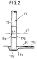
- a liquid residue 14 is shown which exceeds the top of the countersinking 11, while in Fig. 2 a considerably smaller liquid residue 14' is shown which is only to be found in the countersinking 11 itself.
- the countersinking 11 is illustrated with a main bottom portion 11a, which cooperates with an intake 12a to the first draining arrangement 12.
- the countersinking is shown with a local bottom portion 11b submerged in relation to the main bottom portion 11a, which cooperates with a lower intake 13a to the second draining arrangement 13, as is best evident from Fig. 2.
- the second draining arrangement 13 comprises a rigid drain pipe 15, which extends from a lower level just above the bottom portion 11b to an upper level to a displacement pump 16 (see Fig. 1).
- the displacement pump 16 is arranged above and outside the tank 10, but can if necessary be submerged in the tank, for example arranged in a cofferdam at the upper portion of the tank (not shown further).
- the supply of gas medium is shod with arrows A in Fig. 1 from the tank 10 to the interior of the drain pipe 15 for different levels at a1 and a2 of the drain pipe.
- a single or more than the illustrated two levels can be employed for the supply of gas medium to the drain pipe.
- a discharge conduit 17 extends to a storage container (not shown further), in which gas medium is separated from liquid medium.
- the conduit 17 can lead to the same delivery location which the remaining contents of the tank are delivered to.
- an ejector (not shown further) can for example be employed, which for example can be arranged above and outside the tank.
- a lower portion of the drain pipe 15 is shown during operation of the pump 16, where the drain pipe below the level a1 is supposed to contain sucked in liquid having a specific gravity of for example 1 kg./dm 3 , while an overlying portion of the drain pipe above the level a1 is shown with a mixture of gas and liquid having a density of for example 0.75 kg./dm 3 , which is obtained by the supply of a throttled current of gas medium, as illustrated by the arrows A at the level a1.
- a gas/liquid mixture can be obtained having a density of for example 0.3 kg./dm 3 achieved by the supply of a throttled current of gas medium as illustrated by the arrows A at the level a2 (Fig. 1).
- the density of the gas/liquid mixture can correspondingly be further reduced by the additional supply of throttled gas medium.
- the whole quantity of gas medium can be supplied at one and the same level.
- Gas medium supply to the drain pipe is illustrated in Fig. 2 via two diametrically opposed throttle nozzle openings 19a, 19b at the level a1. corresponding throttle nozzle openings can be employed at the level a2.
- annular series of openings can be employed at one of the levels or at each level, instead of the two opposed openings illustrated.
- the various openings can have different cross-sectional openings and/or different directional paths in order to supply gas medium in different amounts and in a different manner so as to mix the gas medium with the liquid medium in the drain pipe in a different way.
- a gas supply conduit 100 for feeding inert gas from a source of inert gas (not shown) via a regulating valve 100' to the interior of the tank.
- a certain excess pressure for example 0,1 bar
- a draining arrangement 13' is shown according to an alternative construction, where the substantial departure relative to the construction in Fig. 1 and 2 consists in the drain pipe 15' being illustrated without throttle nozzle openings 19a, 19b, as shown in Fig. 2, while gas medium is fed separately through an extra gas medium conduit 21 which is arranged internally in the drain pipe 15', which is unperforated.
- the conduit 21 is shown in broken lines.
- the gas discharge openings can be arranged in different angular positions relative to the drain pipe in order to obtain further different flow effects and mixing effects internally in the drain pipe.
- a gas medium conduit 21 is shown having a closed lower end 21a and having throttle nozzle openings 22a, 22b disposed at a level a1.
- gas medium can be fed in different quantities and with different pressures as required.
- the lower end of the gas medium conduit 21' is provided with an ejector 25 which forms an ejector effect internally in the drain pipe 15' at a level a1 at the lower end 15a of the pipe 15'.
- the solution as shown in Fig. 5 in combination with the solution as illustrated in Fig. 1 and 2.
- the gas medium is discharged into the drain pipe 15' in a concentrated stream of compressed air lowermost in the drain pipe, preferably in a compressed air stream directed vertically upwards from an upwardly directed outlet 25a at the lower end of the gas medium conduit 21.
- the ejector effect can be exerted just at or just above the liquid residue 14' at the intake opening of the drain pipe and thereby produces a significant change in the density of the transport medium (the gas/liquid mixture) already at a level a1 at the lower end of the drain pipe and at the same time brings about a significant extra suction effect at the lower intake opening of the drain pipe.
- the solution with the ejector effect can be employed together with overlying (downstream) throttle nozzle openings in the drain pipe 15 (Fig.
Landscapes
- Engineering & Computer Science (AREA)
- Mechanical Engineering (AREA)
- General Engineering & Computer Science (AREA)
- Chemical & Material Sciences (AREA)
- Combustion & Propulsion (AREA)
- Ocean & Marine Engineering (AREA)
- Physics & Mathematics (AREA)
- Fluid Mechanics (AREA)
- Cleaning In General (AREA)
- Jet Pumps And Other Pumps (AREA)
- Filling Or Discharging Of Gas Storage Vessels (AREA)
- Physical Water Treatments (AREA)
- Cleaning By Liquid Or Steam (AREA)
- Photographic Developing Apparatuses (AREA)
- Filtration Of Liquid (AREA)
- Treatment Of Sludge (AREA)
Applications Claiming Priority (4)
| Application Number | Priority Date | Filing Date | Title |
|---|---|---|---|
| NO920380 | 1992-01-28 | ||
| NO920380A NO174460C (no) | 1992-01-28 | 1992-01-28 | Fremgangsmåte og arrangement for tömming av en væskerest fra bunnen av en tank |
| PCT/NO1992/000180 WO1993014969A1 (fr) | 1992-01-28 | 1992-11-02 | Procede et systeme d'evacuation d'un residu liquide du fond d'un reservoir |
| EP93900466A EP0623084B1 (fr) | 1992-01-28 | 1992-11-02 | Procede et systeme d'evacuation d'un residu liquide du fond d'un reservoir |
Related Parent Applications (2)
| Application Number | Title | Priority Date | Filing Date |
|---|---|---|---|
| EP93900466A Division EP0623084B1 (fr) | 1992-01-28 | 1992-11-02 | Procede et systeme d'evacuation d'un residu liquide du fond d'un reservoir |
| EP93900466.9 Division | 1993-08-08 |
Publications (3)
| Publication Number | Publication Date |
|---|---|
| EP0839708A2 true EP0839708A2 (fr) | 1998-05-06 |
| EP0839708A3 EP0839708A3 (fr) | 1999-12-01 |
| EP0839708B1 EP0839708B1 (fr) | 2004-10-27 |
Family
ID=19894822
Family Applications (2)
| Application Number | Title | Priority Date | Filing Date |
|---|---|---|---|
| EP97203502A Expired - Lifetime EP0839708B1 (fr) | 1992-01-28 | 1992-11-02 | Procédé et système d'évacuation d'un résidu liquide du fond d'un réservoir |
| EP93900466A Expired - Lifetime EP0623084B1 (fr) | 1992-01-28 | 1992-11-02 | Procede et systeme d'evacuation d'un residu liquide du fond d'un reservoir |
Family Applications After (1)
| Application Number | Title | Priority Date | Filing Date |
|---|---|---|---|
| EP93900466A Expired - Lifetime EP0623084B1 (fr) | 1992-01-28 | 1992-11-02 | Procede et systeme d'evacuation d'un residu liquide du fond d'un reservoir |
Country Status (6)
| Country | Link |
|---|---|
| EP (2) | EP0839708B1 (fr) |
| AT (2) | ATE166301T1 (fr) |
| AU (1) | AU3174093A (fr) |
| DE (2) | DE69225608D1 (fr) |
| NO (1) | NO174460C (fr) |
| WO (1) | WO1993014969A1 (fr) |
Cited By (1)
| Publication number | Priority date | Publication date | Assignee | Title |
|---|---|---|---|---|
| RU2401765C1 (ru) * | 2009-04-14 | 2010-10-20 | Федеральное государственное образовательное учреждение высшего профессионального образования "Астраханский государственный технический университет" | Грузовая система наливного судна |
Families Citing this family (2)
| Publication number | Priority date | Publication date | Assignee | Title |
|---|---|---|---|---|
| NO300964B1 (no) * | 1995-08-10 | 1997-08-25 | Mohn Fusa As Frank | Anordning ved lossepumpe som er neddykkbar i lasten i en skipslastetank |
| DE19625992C1 (de) * | 1996-06-28 | 1997-10-02 | Bornemann J H Gmbh & Co | Verfahren und Einrichtung zur Tankentleerung |
Family Cites Families (7)
| Publication number | Priority date | Publication date | Assignee | Title |
|---|---|---|---|---|
| US3072057A (en) * | 1959-03-04 | 1963-01-08 | Rosa Esau Da Silva | Pumping system or apparatus for deep wells |
| NO123115B (fr) * | 1967-10-18 | 1971-09-27 | Patents & Dev As | |
| NO121316B (fr) * | 1968-10-23 | 1971-02-08 | Patents & Developments A S | |
| NO141403C (no) * | 1977-10-10 | 1980-03-05 | Patents & Dev As | Anordning ved toemmepumpe. |
| US4392532A (en) * | 1979-03-05 | 1983-07-12 | Raggio Ivan J | Minimum temperature correction method for locating and setting gas-lift valves |
| NO160766C (no) * | 1982-09-21 | 1991-12-24 | Thune Eureka As | Strippesystem for en lastetank. |
| US4596511A (en) * | 1984-06-05 | 1986-06-24 | Eddy Pump Corporation | Eddy pump |
-
1992
- 1992-01-28 NO NO920380A patent/NO174460C/no not_active IP Right Cessation
- 1992-11-02 DE DE69225608T patent/DE69225608D1/de not_active Expired - Lifetime
- 1992-11-02 EP EP97203502A patent/EP0839708B1/fr not_active Expired - Lifetime
- 1992-11-02 AT AT93900466T patent/ATE166301T1/de not_active IP Right Cessation
- 1992-11-02 AT AT97203502T patent/ATE280706T1/de not_active IP Right Cessation
- 1992-11-02 EP EP93900466A patent/EP0623084B1/fr not_active Expired - Lifetime
- 1992-11-02 AU AU31740/93A patent/AU3174093A/en not_active Abandoned
- 1992-11-02 WO PCT/NO1992/000180 patent/WO1993014969A1/fr not_active Ceased
- 1992-11-02 DE DE69233440T patent/DE69233440D1/de not_active Expired - Fee Related
Cited By (1)
| Publication number | Priority date | Publication date | Assignee | Title |
|---|---|---|---|---|
| RU2401765C1 (ru) * | 2009-04-14 | 2010-10-20 | Федеральное государственное образовательное учреждение высшего профессионального образования "Астраханский государственный технический университет" | Грузовая система наливного судна |
Also Published As
| Publication number | Publication date |
|---|---|
| EP0623084B1 (fr) | 1998-05-20 |
| NO920380L (no) | 1993-07-29 |
| AU3174093A (en) | 1993-09-01 |
| EP0623084A1 (fr) | 1994-11-09 |
| EP0839708B1 (fr) | 2004-10-27 |
| NO920380D0 (no) | 1992-01-28 |
| ATE280706T1 (de) | 2004-11-15 |
| EP0839708A3 (fr) | 1999-12-01 |
| NO174460C (no) | 1996-09-17 |
| ATE166301T1 (de) | 1998-06-15 |
| DE69233440D1 (de) | 2004-12-02 |
| NO174460B (no) | 1994-01-31 |
| WO1993014969A1 (fr) | 1993-08-05 |
| DE69225608D1 (de) | 1998-06-25 |
Similar Documents
| Publication | Publication Date | Title |
|---|---|---|
| US4715721A (en) | Transportable integrated blending system | |
| KR100203218B1 (ko) | 파우더 코팅장치 | |
| EP1420868B1 (fr) | Injecteur de fluide comportant des orifices d'event/dosage | |
| WO2004074629B1 (fr) | Compresseur sous-marin | |
| US3895885A (en) | Emptying system for fluid tanks | |
| US20090220324A1 (en) | Drill cuttings storage and conveying | |
| PL154426B1 (en) | Device for manufacturing a stream of abrasive mixture | |
| WO2000056664A8 (fr) | Separateur par gravite multidirectionnel | |
| US5151177A (en) | Method and apparatus for dissolved air flotation with aeration | |
| EP0783365B1 (fr) | Module de melange | |
| EP0839708A2 (fr) | Procédé et système d'évacuation d'un résidu liquide du fond d'un réservoir | |
| US6458191B1 (en) | Separator inlet | |
| KR20000075787A (ko) | 기포 승강기를 구비한 용기의 내용물 교반 장치 | |
| WO1996008143B1 (fr) | Appareil et procede de production d'un decor pour aquarium | |
| CA2052829A1 (fr) | Appareil pour melanger des liquides | |
| WO2007049244A1 (fr) | Separateur gravitationnel et procede de separation d'un melange contenant de l'eau, de l'huile et du gaz | |
| US3628660A (en) | Separator for nonmiscible liquids | |
| JPS62195498A (ja) | 液体汲み上げ方法及び装置 | |
| US5858071A (en) | Water-purifying apparatus | |
| US3094135A (en) | Arrangement for feeding a reagent in amounts proportional to the output of water to be treated by said reagent | |
| US3815329A (en) | System for unloading oil | |
| CA2230306A1 (fr) | Systeme dessableur pour reservoirs a hydrocarbures | |
| EP0067218A1 (fr) | Melangeur de liquides | |
| JPS6353087B2 (fr) | ||
| SU856576A1 (ru) | Емкость дл приема,перемешивани и подачи жидкости на распыление |
Legal Events
| Date | Code | Title | Description |
|---|---|---|---|
| PUAI | Public reference made under article 153(3) epc to a published international application that has entered the european phase |
Free format text: ORIGINAL CODE: 0009012 |
|
| AC | Divisional application: reference to earlier application |
Ref document number: 623084 Country of ref document: EP |
|
| AK | Designated contracting states |
Kind code of ref document: A2 Designated state(s): AT BE CH DE DK ES FR GB GR IE IT LI LU MC NL SE |
|
| PUAL | Search report despatched |
Free format text: ORIGINAL CODE: 0009013 |
|
| RIC1 | Information provided on ipc code assigned before grant |
Free format text: 6B 63B 27/24 A, 6B 63B 13/00 B, 6F 04F 1/20 B, 6E 21B 43/12 - |
|
| AK | Designated contracting states |
Kind code of ref document: A3 Designated state(s): AT BE CH DE DK ES FR GB GR IE IT LI LU MC NL SE |
|
| 17P | Request for examination filed |
Effective date: 20000529 |
|
| GRAP | Despatch of communication of intention to grant a patent |
Free format text: ORIGINAL CODE: EPIDOSNIGR1 |
|
| GRAS | Grant fee paid |
Free format text: ORIGINAL CODE: EPIDOSNIGR3 |
|
| GRAA | (expected) grant |
Free format text: ORIGINAL CODE: 0009210 |
|
| AC | Divisional application: reference to earlier application |
Ref document number: 0623084 Country of ref document: EP Kind code of ref document: P |
|
| AK | Designated contracting states |
Kind code of ref document: B1 Designated state(s): AT BE CH DE DK ES FR GB GR IE IT LI LU MC NL SE |
|
| PG25 | Lapsed in a contracting state [announced via postgrant information from national office to epo] |
Ref country code: SE Free format text: LAPSE BECAUSE OF FAILURE TO SUBMIT A TRANSLATION OF THE DESCRIPTION OR TO PAY THE FEE WITHIN THE PRESCRIBED TIME-LIMIT Effective date: 20041027 Ref country code: LI Free format text: LAPSE BECAUSE OF FAILURE TO SUBMIT A TRANSLATION OF THE DESCRIPTION OR TO PAY THE FEE WITHIN THE PRESCRIBED TIME-LIMIT Effective date: 20041027 Ref country code: IT Free format text: LAPSE BECAUSE OF FAILURE TO SUBMIT A TRANSLATION OF THE DESCRIPTION OR TO PAY THE FEE WITHIN THE PRESCRIBED TIME-LIMIT;WARNING: LAPSES OF ITALIAN PATENTS WITH EFFECTIVE DATE BEFORE 2007 MAY HAVE OCCURRED AT ANY TIME BEFORE 2007. THE CORRECT EFFECTIVE DATE MAY BE DIFFERENT FROM THE ONE RECORDED. Effective date: 20041027 Ref country code: FR Free format text: LAPSE BECAUSE OF FAILURE TO SUBMIT A TRANSLATION OF THE DESCRIPTION OR TO PAY THE FEE WITHIN THE PRESCRIBED TIME-LIMIT Effective date: 20041027 Ref country code: CH Free format text: LAPSE BECAUSE OF FAILURE TO SUBMIT A TRANSLATION OF THE DESCRIPTION OR TO PAY THE FEE WITHIN THE PRESCRIBED TIME-LIMIT Effective date: 20041027 Ref country code: BE Free format text: LAPSE BECAUSE OF FAILURE TO SUBMIT A TRANSLATION OF THE DESCRIPTION OR TO PAY THE FEE WITHIN THE PRESCRIBED TIME-LIMIT Effective date: 20041027 Ref country code: AT Free format text: LAPSE BECAUSE OF FAILURE TO SUBMIT A TRANSLATION OF THE DESCRIPTION OR TO PAY THE FEE WITHIN THE PRESCRIBED TIME-LIMIT Effective date: 20041027 |
|
| REG | Reference to a national code |
Ref country code: GB Ref legal event code: FG4D |
|
| REG | Reference to a national code |
Ref country code: CH Ref legal event code: EP |
|
| PG25 | Lapsed in a contracting state [announced via postgrant information from national office to epo] |
Ref country code: LU Free format text: LAPSE BECAUSE OF NON-PAYMENT OF DUE FEES Effective date: 20041102 Ref country code: IE Free format text: LAPSE BECAUSE OF NON-PAYMENT OF DUE FEES Effective date: 20041102 |
|
| PG25 | Lapsed in a contracting state [announced via postgrant information from national office to epo] |
Ref country code: MC Free format text: LAPSE BECAUSE OF NON-PAYMENT OF DUE FEES Effective date: 20041130 |
|
| REG | Reference to a national code |
Ref country code: IE Ref legal event code: FG4D |
|
| REF | Corresponds to: |
Ref document number: 69233440 Country of ref document: DE Date of ref document: 20041202 Kind code of ref document: P |
|
| PG25 | Lapsed in a contracting state [announced via postgrant information from national office to epo] |
Ref country code: GR Free format text: LAPSE BECAUSE OF FAILURE TO SUBMIT A TRANSLATION OF THE DESCRIPTION OR TO PAY THE FEE WITHIN THE PRESCRIBED TIME-LIMIT Effective date: 20050127 Ref country code: DK Free format text: LAPSE BECAUSE OF FAILURE TO SUBMIT A TRANSLATION OF THE DESCRIPTION OR TO PAY THE FEE WITHIN THE PRESCRIBED TIME-LIMIT Effective date: 20050127 |
|
| PG25 | Lapsed in a contracting state [announced via postgrant information from national office to epo] |
Ref country code: ES Free format text: LAPSE BECAUSE OF FAILURE TO SUBMIT A TRANSLATION OF THE DESCRIPTION OR TO PAY THE FEE WITHIN THE PRESCRIBED TIME-LIMIT Effective date: 20050207 |
|
| REG | Reference to a national code |
Ref country code: CH Ref legal event code: PL |
|
| PG25 | Lapsed in a contracting state [announced via postgrant information from national office to epo] |
Ref country code: DE Free format text: LAPSE BECAUSE OF NON-PAYMENT OF DUE FEES Effective date: 20050601 |
|
| REG | Reference to a national code |
Ref country code: IE Ref legal event code: MM4A |
|
| PLBE | No opposition filed within time limit |
Free format text: ORIGINAL CODE: 0009261 |
|
| STAA | Information on the status of an ep patent application or granted ep patent |
Free format text: STATUS: NO OPPOSITION FILED WITHIN TIME LIMIT |
|
| 26N | No opposition filed |
Effective date: 20050728 |
|
| EN | Fr: translation not filed | ||
| PGFP | Annual fee paid to national office [announced via postgrant information from national office to epo] |
Ref country code: NL Payment date: 20120330 Year of fee payment: 20 |
|
| PGFP | Annual fee paid to national office [announced via postgrant information from national office to epo] |
Ref country code: GB Payment date: 20120411 Year of fee payment: 20 |
|
| REG | Reference to a national code |
Ref country code: NL Ref legal event code: V4 Effective date: 20121102 |
|
| REG | Reference to a national code |
Ref country code: GB Ref legal event code: PE20 Expiry date: 20121101 |
|
| PG25 | Lapsed in a contracting state [announced via postgrant information from national office to epo] |
Ref country code: GB Free format text: LAPSE BECAUSE OF EXPIRATION OF PROTECTION Effective date: 20121101 |