EP0839714B1 - Doppelhub-Spannhebelverschluss - Google Patents
Doppelhub-Spannhebelverschluss Download PDFInfo
- Publication number
- EP0839714B1 EP0839714B1 EP19970202901 EP97202901A EP0839714B1 EP 0839714 B1 EP0839714 B1 EP 0839714B1 EP 19970202901 EP19970202901 EP 19970202901 EP 97202901 A EP97202901 A EP 97202901A EP 0839714 B1 EP0839714 B1 EP 0839714B1
- Authority
- EP
- European Patent Office
- Prior art keywords
- handle
- over center
- hook arm
- inner handle
- link
- Prior art date
- Legal status (The legal status is an assumption and is not a legal conclusion. Google has not performed a legal analysis and makes no representation as to the accuracy of the status listed.)
- Expired - Lifetime
Links
- 238000000034 method Methods 0.000 claims description 10
- 238000012423 maintenance Methods 0.000 description 5
- 230000036316 preload Effects 0.000 description 3
- 238000005452 bending Methods 0.000 description 2
- 230000006835 compression Effects 0.000 description 2
- 238000007906 compression Methods 0.000 description 2
- 230000001419 dependent effect Effects 0.000 description 2
- 238000007689 inspection Methods 0.000 description 2
- 230000000881 depressing effect Effects 0.000 description 1
Images




Classifications
-
- E—FIXED CONSTRUCTIONS
- E05—LOCKS; KEYS; WINDOW OR DOOR FITTINGS; SAFES
- E05C—BOLTS OR FASTENING DEVICES FOR WINGS, SPECIALLY FOR DOORS OR WINDOWS
- E05C19/00—Other devices specially designed for securing wings, e.g. with suction cups
- E05C19/10—Hook fastenings; Fastenings in which a link engages a fixed hook-like member
- E05C19/12—Hook fastenings; Fastenings in which a link engages a fixed hook-like member pivotally mounted around an axis
- E05C19/14—Hook fastenings; Fastenings in which a link engages a fixed hook-like member pivotally mounted around an axis with toggle action
- E05C19/145—Hook fastenings; Fastenings in which a link engages a fixed hook-like member pivotally mounted around an axis with toggle action flush
-
- B—PERFORMING OPERATIONS; TRANSPORTING
- B64—AIRCRAFT; AVIATION; COSMONAUTICS
- B64D—EQUIPMENT FOR FITTING IN OR TO AIRCRAFT; FLIGHT SUITS; PARACHUTES; ARRANGEMENT OR MOUNTING OF POWER PLANTS OR PROPULSION TRANSMISSIONS IN AIRCRAFT
- B64D29/00—Power-plant nacelles, fairings or cowlings
- B64D29/06—Attaching of nacelles, fairings or cowlings
-
- Y—GENERAL TAGGING OF NEW TECHNOLOGICAL DEVELOPMENTS; GENERAL TAGGING OF CROSS-SECTIONAL TECHNOLOGIES SPANNING OVER SEVERAL SECTIONS OF THE IPC; TECHNICAL SUBJECTS COVERED BY FORMER USPC CROSS-REFERENCE ART COLLECTIONS [XRACs] AND DIGESTS
- Y10—TECHNICAL SUBJECTS COVERED BY FORMER USPC
- Y10S—TECHNICAL SUBJECTS COVERED BY FORMER USPC CROSS-REFERENCE ART COLLECTIONS [XRACs] AND DIGESTS
- Y10S292/00—Closure fasteners
- Y10S292/31—Lever operator, flush
-
- Y—GENERAL TAGGING OF NEW TECHNOLOGICAL DEVELOPMENTS; GENERAL TAGGING OF CROSS-SECTIONAL TECHNOLOGIES SPANNING OVER SEVERAL SECTIONS OF THE IPC; TECHNICAL SUBJECTS COVERED BY FORMER USPC CROSS-REFERENCE ART COLLECTIONS [XRACs] AND DIGESTS
- Y10—TECHNICAL SUBJECTS COVERED BY FORMER USPC
- Y10T—TECHNICAL SUBJECTS COVERED BY FORMER US CLASSIFICATION
- Y10T292/00—Closure fasteners
- Y10T292/08—Bolts
- Y10T292/0911—Hooked end
- Y10T292/0945—Operating means
- Y10T292/0949—Lever
-
- Y—GENERAL TAGGING OF NEW TECHNOLOGICAL DEVELOPMENTS; GENERAL TAGGING OF CROSS-SECTIONAL TECHNOLOGIES SPANNING OVER SEVERAL SECTIONS OF THE IPC; TECHNICAL SUBJECTS COVERED BY FORMER USPC CROSS-REFERENCE ART COLLECTIONS [XRACs] AND DIGESTS
- Y10—TECHNICAL SUBJECTS COVERED BY FORMER USPC
- Y10T—TECHNICAL SUBJECTS COVERED BY FORMER US CLASSIFICATION
- Y10T292/00—Closure fasteners
- Y10T292/08—Bolts
- Y10T292/096—Sliding
- Y10T292/1014—Operating means
- Y10T292/1015—Link and lever
Definitions
- This invention relates to an improved latch for securing together two members and more particularly, but not by way of limitation, to a latch for securing together a pair of hinged cowlings or ducts of an aircraft nacelle.
- the invention relates to a latch as defined in the preamble of claim 1 and a method of latching as defined in the preamble of claim 6.
- Such a latch and method are known from FR-A-2 624 905.
- Modern jet engines commonly include a pair of thrust reverser ducts or cowls that, during aircraft operation, define the outer walls of the engine exhaust nozzle.
- Such thrust reverser ducts must he capable of withstanding considerable loads caused by the high pressure of the jet exhaust stream, which it contains.
- the thrust reverser ducts are normally hingedly connected to the upper portion of the nacelle near the point where the nacelle is attached to the engine support strut.
- the ducts can he pivoted upwards about their hinge points to provide access to the engine for maintenance and repair.
- the ducts are pivoted downwards into closed positions in which their lower ends are adjacent to one another, or adjacent to an interposed strut, services channel or bifurcation.
- the closed ducts are then secured by latches to form a continuous circumferential load bearing structure.
- thrust reverser ducts must have an appreciable thickness to accommodate flow reversing cascades, and the inner surfaces of the ducts must include a load bearing member or ring to withstand the aforementioned loads due to internal pressure. Furthermore, a large circumferential force must he applied during latching to ensure satisfactory flange seating.
- FIG. 1 An example of such an existing latch is illustrated in the above-identified prior art document FR-A-2 624 905.
- This prior art latch is rotatably mounted about a mounting bushing at one end of a pair of compression links whose opposite end pivotally mounts a hook that engages a keeper mounted on one of two members to be joined by the latch.
- Mounted at the pivot point between the hook and compression links is a first part of a two part handle whose second part is attached from the first handle part to a pair of side plates that form a further linkage.
- the side plates rotate about the mounting bushing, while the opposite ends thereof are connected by control links to the hook.
- the existing latches have had to compromise between the handle force necessary to close the latch and the length of the take-up stroke. For instance, the need has been to have a latch wherein typically 220 N (50 lbs.) of handle operating force would allow for a take-up of typically 6.35 cm (2.5 inches) within a limited operating envelope that limits handle size. The problem has traditionally been resolved by allowing increased handle operating force or reduced take-up stroke. In some instances, a force of 580 N (130 lbs.) was required. The existing latch does not accomplish any work during handle folding, so all of the take-up must be accomplished in a single take-up stroke.
- the invention has for its object to provide an improved latch. In accordance with the invention, this is achieved in a latch of the type described above by the characterizing features of claim 1.
- the structure defined in this claim, including a second over center linkage, allows the take-up to occur over both the closing stroke and the folding stroke by adding additional links which allow the action of folding the outer handle to also accomplish work.
- Preferred embodiments of the latch of the invention form the subject-matter of dependent claims 2 to 5.
- the invention further has for its object to provide an improved latching method. In accordance with the invention, this is achieved by a method of closing a latch having the features of claim 6. Preferred ways of carrying out the inventive method are defined in dependent claims 7 to 10.
- the first stroke of the latch operates in the same fashion as in prior art latches, but only accomplishes a portion of the total required take-up with the primary link and the inner handle being over center to engage the inner handle trigger.
- the outer handle release trigger prevents the relationship between the outer handle, the inner handle, die idler link, the rocker link and the secondary link from changing as the inner handle is rotated about the hook arm pivot.
- the second stroke of the latch, or the folding stroke is initiated by depressing the outer handle release trigger and rotating the outer handle about the outer handle pivot towards the hook arm pivot.
- the mechanical advantage of the outer handle is transmitted through the idler link into the rocker link and the secondary link. Additional mechanical advantage is gained at the rocker link to secondary link connection as they are positioned over center.
- the first detent position of the outer handle release trigger holds the outer handle, the idler link, the rocker link and the secondary link in the over center position.
- the second over center action provides the final take-up to achieve the desired total take-up. Both strokes arc accomplished with a handle force lower than previously achieved by operating over two smaller strokes.
- a jet engine nacelle 10 comprising an inlet assembly 12 , thrust reverser assembly 22 , core assembly 30 and fan cowls 18 and 20 .
- a fan 16 is part of the jet engine and is shown for reference.
- Each fan cowl 18 and 20 is capable of being moved between an open, maintenance position, as illustrated by fan cowl 18 , and a closed, operating position, as illustrated by fan cowl 20 . Both fan cowls pivot about hinge points near the upper portion of nacelle 10 .
- the thrust reverser assembly 22 comprises the thrust reverser ducts 24 and 26 .
- Each thrust reverser duct is capable of being moved between an open, maintenance position, as illustrated by the thrust reverser duct 24 , and a closed, operating position, as illustrated by the thrust reverser duct 26 .
- the fan 16 forces air through an exhaust nozzle (not shown) formed between the closed reverser ducts and the core assembly 30 .
- this airflow is interrupted, and the air is instead forced through a plurality of flow reversing cascades (not shown) in the thrust reverser ducts.
- the thrust reverser ducts 24 and 26 are subjected to substantial hoop loads caused by high pressure air flowing therein, and the system for latching the thrust reverser ducts in their closed positions must be adapted to withstand and transmit such loads.
- the system for latching the thrust reverser ducts 24 and 26 needs to be accessible. During inspection and maintenance, it is necessary for the thrust reverser 24 and 26 ducts to be unlatched so that they can be opened in order to access the engine. It is also necessary for the latches to be closed again after inspection. So, it is necessary to have a latch which is capable of withstanding and transmitting the substantial loads produced by the air flowing within the aircraft engine, and yet be readily operable, both during engagement and disengagement.
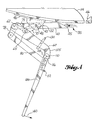
- FIG. 2 shows an embodiment of the latch according to this invention in a fully opened position.
- a keeper 35 is attached (due to the scale the attachment is not shown) to a duct 26 , shown on the right in the figures.
- a hook arm 40 has a slot 42 and a hook 45 .
- the hook arm 40 is slidably mounted over a bolt 48 attached to a mounting base 46 on duct 24 , shown on the left in the figures, such that the slot 42 is mounted over the bolt 48 .
- the mounting base 46 and the keeper 35 may be either mounted directly to the ducts 24 and 26 or to hoops (not shown).
- the hook 45 is adapted to engage the keeper 35 .
- Either the hook arm 40 or the keeper 35 will typically have a preload and a preload adjustment, not shown, that is well known. While reference is made to a hook, one skilled in the art will know of additional devices which can be used to engage the keeper.
- An inner handle 60 is pivotally connected at one end to the hook arm 40 at the hook arm pivot 62 .
- the inner handle has a slot 65 .
- a primary link 70 is pivotally connected at one end to the bolt 48 . The opposite end is pivotally connected to the inner handle 60 and slidably engaged in the slot 65 .
- a secondary link 75 is pivotally connected to the primary link 70 and is also slidably engaged in the slot 65 .
- a rocker link 78 is pivotally connected to the hook arm pivot 62 and pivotally connected to the secondary link 75 at the end of the secondary link opposite the connection to the primary link 70 .
- the connection between the rocker link 78 and the secondary link 75 is shown to the right of the hook arm pivot 62 .
- An idler link 80 is pivotally connected to the rocker link 78 shown to the left of the hook arm pivot 62 , and on the opposite side of the hook arm pivot 62 from the connection to the secondary link 75 .
- An outer handle 100 is pivotally connected to the idler link 80 .
- the outer handle 100 is also pivotally connected to the inner handle 60 at the handle pivot 110 .
- a first overcenter linkage is formed by the inner handle 60 pivotally attached to an end of the hook ann 40 opposite the keeper 35 and the primary link 70 attached to the base 46 and the inner handle 60 .
- a second over center linkage is formed by the outer handle 100 pivotally connected to the inner handle 60 , an idler link 80 connected to the outer handle 100 , a rocker link 78 pivotally connected to the inner handle 60 and the hook arm 40 and a secondary link 75 pivotally connected between the rocker link 78 and the primary link 70 .
- An outer handle trigger 112 is located within the outer handle 100 . Referring to FIG. 3 , the outer handle trigger 112 can lockingly engage in detents 116 and 118 of the inner handle 60 . Referring again to FIG. 2 , when the outer handle trigger 112 is engaged with the detent 116 , the relationship between the outer handle 100 , the inner handle 60 , the idler link 80 , the rocker link 78 and the secondary link 75 is fixed, so that the entire set of fixed handles and links acts as a single unit, referred to as the closing handle unit 125 .
- An inner handle trigger 130 is mounted to the inner handle 60 and engages with a pin 132 on the hook arm 40 when the inner handle 60 completes the closing stroke.
- the link elements are balanced such that the mounting base 46 extends on both sides of the hook arm 40 and the primary link 70 .
- the primary link 70 , the inner handle 60 , the secondary link 75 and the rocker link 78 are also on both sides of the hook arm 40 .
- the remaining link elements may also be balanced about the hook arm.
- the cowlings or ducts 24 and 26 arc closed and the hook 45 is engaged with the keeper 35 .
- the outer handle release trigger 112 is engaged with the first detent 116 in the inner handle 60, which locks the outer handle 100, the inner handle 60, the idler link 80, the rocker link 78 and the secondary link 75 to form the closing handle unit 125 .
- the closing handle unit 125 moves as a single unit when the outer handle release trigger 112 is engaged in the first detent 116 .
- the closing handle is moved toward the right, in a counter-clockwise direction, as shown by the arrow 140 in FIG.
- the hook arm 40 is forced to the left as shown by arrow 141 drawing the keeper 35 along to the left.
- the primary link 70 is fixed to the bolt 48 , so the hook arm 40 moves slidably to the left such that the slot 42 travels over the bolt 48 until the primary link 70 is substantially parallel and in line with the hook arm 40 , and the inner handle release trigger 130 engages the pin 132 on the hook arm 40 .
- the outer handle release trigger 112 is slid back toward the end of the outer handle 100 .
- the outer handle release trigger 112 released, the outer handle 100 , the inner handle 60, the idler link 80 , the rocker link 78 and the secondary link 75 are all free to move and rotate in relation to each other as they remain pivotally connected.
- the hook arm 40 and the inner handle 60 arc securely fixed to each other by the inner handle release trigger 130 .
- the outer handle 100 is moved towards the left, clockwise, as shown by the arrow 142 in FIG. 5 .
- This movement forces the idler link 80 to move toward the left, which forces the rocker link 78 to rotate about its pivotal connection to the hook arm 40 and the inner handle 60 .
- the rocker link 78 rotates, the hook arm 40 and the inner handle 60 are forced to the left as the secondary link 75 moves toward a position substantially parallel and in line with the hook arm 40 .
- This movement allows the folding stroke to also do work and provide additional take-up. By dividing the desired take-up over the closing stroke and the folding stroke, the force needed for any one stroke is reduced while the take-up distance is maintained.
- the combination of strokes also enables a higher preload to be achieved without having to increase the necessary force for a single stroke.
- FIG. 6 an embodiment of the present latch is shown closed.
- the secondary link 75 is located substantially parallel and in line with the hook arm 40 .
- the outer handle release trigger 112 is engaged into the detent 118 in the inner handle 60 , securing the outer handle 100 , the idler link 80 , the rocker link 78 , and the secondary link 75 so that they are in a fixed relative position and secured for normal engine operation.
- the thrust reverser duct or cowling can be opened to access the engine for maintenance and repair.
- the outer handle release trigger 112 is released so that the outer handle 100 can be moved to the right, counter-clockwise, as shown by the arrow 144 in FIG. 7 .
- the movement of the outer handle 100 will cause the idler link 80 , the rocker link 78 , and the secondary link 75 to move forcing the hook arm 40 to the right.
- the outer handle 100 continues to move until the outer handle release trigger 112 engages with the detent 116 , as shown in FIG. 8 .
- the inner handle release trigger 130 can be released.
- the outer handle 100 can then be moved to the left, which forces the hook arm 40 further to the right until the hook 45 can be disengaged from the keeper 35 and the ducts 24 and 26 can be opened.
Landscapes
- Engineering & Computer Science (AREA)
- Mechanical Engineering (AREA)
- Aviation & Aerospace Engineering (AREA)
- Mutual Connection Of Rods And Tubes (AREA)
- Mechanical Control Devices (AREA)
- Quick-Acting Or Multi-Walled Pipe Joints (AREA)
Claims (10)
- Verschluss, um zwei bewegliche Elemente (24, 26) miteinander zu verriegeln, umfassend:gekennzeichnet durch eine zweite Spannhebelverbindung (75, 78, 80, 100) umfassend einen äußeren Einstellhebel (100) und eine Vielzahl von Verbindungselementen (75, 78, 80), wobei der äußere Einstellhebel (100) und eines (78) der Verbindungselemente schwenkbar mit dem inneren Einstellhebel (60) der ersten Spannhebelverbindung (60, 70) verbunden ist, um das das mit dem Halter in Eingriff gelangende Ende (45) des Hakenarms (40) über einen zweiten Hub durch eine Schwenkbewegung des äußeren Einstellhebels (100) in eine zweite Richtung entgegengesetzt der ersten Richtung zu bewegen, nachdem die erste Spannhebelverbindung (60, 70) am Ende des ersten Hubs fixiert wurde.eine an einem (24) der Elemente anzubringende Basis (46),einen an dem anderen Element (26) anzubringenden Halter (35),einen Hakenarm (40) mit einem Ende (45), um mit dem Halter (35) in Eingriff zu gelangen, wobei der Hakenarm (40) derart mit der Basis (46) verbunden ist, dass er bezüglich der Basis (46) drehbar und verschiebbar ist, undeine erste Spannhebelverbindung (60, 70) umfassend einen inneren Einstellhebel (60) und ein primäres Verbindungselement (70), wobei die Verbindung (60, 70) zwischen einem Ende des Hakenarms (40), welches gegenüberliegend dem mit dem Halter in Eingriff gelangenden Ende (45) davon gelegen ist, und der Basis (46) angeordnet ist, um das mit dem Halter in Eingriff gelangende Ende (45) des Hakenarms (40) über einen ersten Hub durch eine Schwenkbewegung des inneren Einstellhebels (60) in eine erste Richtung zu bewegen,
- Verschluss nach Anspruch 1, dadurch gekennzeichnet, dass der innere Einstellhebel (60) der ersten Spannhebelverbindung (60, 70) schwenkbar an dem Ende des Hakenarms (40) gegenüberliegend des mit dem Halter in Eingriff gelangenden Endes (45) davon angebracht ist, und dass das primäre Verbindungselement (70) schwenkbar zwischen der Basis (46) und dem inneren Einstellhebel (60) angebracht ist.
- Verschluss nach Anspruch 2, dadurch gekennzeichnet, dass die zweite Spannhebelverbindung (75, 78, 80, 100) umfasst:den äußeren Einstellhebel (100), welcher schwenkbar mit einem Ende des inneren Einstellhebels (60) gegenüberliegend dem Hakenarm (40) verbunden ist,ein schwenkbar mit dem inneren Einstellhebel (60) und dem Hakenarm (40) verbundenes Schwingverbindungselement,ein schwenkbar zwischen dem äußeren Einstellhebel (100) und dem Schwingverbindungselement (78) verbundenes Ruheverbindungselement, undein schwenkbar zwischen dem Schwingverbindungselement (78) und dem primären Verbindungselement (70) verbundenes sekundäres Verbindungselement (75).
- Verschluss nach Anspruch 3, dadurch gekennzeichnet, dass
der äußere Einstellhebel (100) einen lösbaren Auslöser (112) umfasst und der innere Einstellhebel (60) zumindest eine erste Raste (116) umfasst, wobei die zweite Spannhebeiverbindung (75, 78, 80, 100) und der innere Einstellhebel (60) eine schließende Hebeleinheit (125) bilden, wenn der Auslöser (112) des äußeren Einstellhebels mit der ersten Raste (116) in Eingriff steht. - Verschluss nach einem der Ansprüche 2 bis 4,
gekennzeichnet durch einen an dem inneren Einstellhebel (60) angebrachten Auslöser (130), welcher mit dem Hakenarm (40) in Eingriff bringbar ist, um den Hakenarm (40) und den inneren Einstellhebel (60) in einer im Wesentlichen feststehenden Beziehung zueinander zu sichern. - Verfahren zum Schließen eines Verschlusses zum Verriegeln zweier beweglicher Elemente (24, 26), umfassend folgende Schritte:gekennzeichnet durch den Schritt des Zwingens einer zweiten Spannhebelverbindung (75, 78, 80, 100), umfassend einen äußeren Einstellhebel (100) und eine Vielzahl von Verbindungselementen (75, 78, 80), wobei der äußere Einstellhebel (100) und eines (78) der Verbindungselemente schwenkbar mit dem inneren Einstellhebel (60) der ersten Spannehebelverbindung (60, 70) verbunden ist, in seine verriegelte Position durch eine Schwenkbewegung des äußeren Einstellhebels (100) in eine zweite Richtung entgegengesetzt der ersten Richtung, wodurch das mit dem Halter in Eingriff stehende Ende des Hakenarms (40) über den zweiten Hub bewegt wird, nachdem die erste Spannhebelverbindung (60, 70) am Ende des ersten Hubs fixiert wurde.In-Eingriff-Bringen eines Endes (45) eines Hakenarms (40), welcher drehbar und verschiebbar mit einer an einem Element angebrachter Basis (46) verbunden ist, mit einem Halter (35), welcher an dem anderen Element angebracht ist, undZwingen einer ersten Spannhebelverbindung (60, 70) umfassend einen inneren Einstellhebel (60) und ein primäres Verbindungselement (70), wobei die Spannhebelverbindung (60, 70) zwischen einem dem mit dem Halter in Eingriff stehenden Ende (45) gegenüberliegend angeordneten Ende des Hakenarms (40) angeordnet ist, in ihre verriegelte Position durch eine Schwenkbewegung des inneren Einstellhebels (60) in eine erste Richtung, wodurch das mit dem Verriegelungselement in Eingriff stehende Ende (45) des Hakenarms (40) über einen ersten Hub bewegt wird,
- Verfahren nach Anspruch 6, dadurch gekennzeichnet, dass die erste Spannhebelverbindung (60, 70) in ihre verriegelte Position gebracht wird, indem der innere Einstellhebel (60) in einem Bogen auf den Hakenarm (40) zubewegt wird, bis das primäre Verbindungselement (70) in einer zu dem Hakenarm (40) parallelen Position ist.
- Verfahren nach Anspruch 7, dadurch gekennzeichnet, dass die erste Spannhebelverbindung (60, 70) durch eine schließende Hebeleinheit (125) in ihre verriegelte Position gebracht wird, welche gebildet wird, indem ein lösbarer Auslöser (112) auf dem äußeren Einstellhebel (100) mit einer ersten Raste (116) in dem inneren Einstellhebel (60) in Eingriff gebracht wird, womit die zweite Spannhebelverbindung (75, 78, 80, 100) und der innere Einstellhebel (60) in einer festen Beziehung zueinander verriegelt werden.
- Verfahren nach Anspruch 8, dadurch gekennzeichnet, dass die zweite Spannhebelverbindung (75, 78, 80, 100) in ihre verriegelt Position gebracht wird, indem der Auslöser (112) aus der ersten Raste (116) in dem inneren Einstellhebel (60) gelöst wird und der äußere Einstellhebel (100) in einem Bogen auf den inneren Einstellhebel (60) zubewegt wird, bis ein sekundäre Verbindungselement (75) in einer im Wesentlichen parallel zu und auf einer Linie mit dem Hakenarm (40) liegenden Position ist.
- Verfahren nach einem der Ansprüche 6 bis 9, dadurch gekennzeichnet, dass ein an dem inneren Einstellhebel (60) angebrachter Auslöser (130) mit dem Hakenarm (40) in Eingriff gebracht wird, nachdem die erste Spannehebelverbindung (60, 70) in ihre verriegelte Position gebracht wurde.
Priority Applications (1)
| Application Number | Priority Date | Filing Date | Title |
|---|---|---|---|
| DE69731712.9T DE69731712T3 (de) | 1996-10-30 | 1997-09-22 | Doppelhub-Spannhebelverschluss |
Applications Claiming Priority (4)
| Application Number | Priority Date | Filing Date | Title |
|---|---|---|---|
| US2968296P | 1996-10-30 | 1996-10-30 | |
| US29682 | 1996-10-30 | ||
| US773727 | 1996-12-21 | ||
| US08/773,727 US6036238A (en) | 1996-10-30 | 1996-12-21 | Double stroke over center latch |
Publications (3)
| Publication Number | Publication Date |
|---|---|
| EP0839714A1 EP0839714A1 (de) | 1998-05-06 |
| EP0839714B1 true EP0839714B1 (de) | 2004-11-24 |
| EP0839714B2 EP0839714B2 (de) | 2016-07-06 |
Family
ID=26705222
Family Applications (1)
| Application Number | Title | Priority Date | Filing Date |
|---|---|---|---|
| EP97202901.1A Expired - Lifetime EP0839714B2 (de) | 1996-10-30 | 1997-09-22 | Doppelhub-Spannhebelverschluss |
Country Status (3)
| Country | Link |
|---|---|
| US (1) | US6036238A (de) |
| EP (1) | EP0839714B2 (de) |
| DE (1) | DE69731712T3 (de) |
Cited By (2)
| Publication number | Priority date | Publication date | Assignee | Title |
|---|---|---|---|---|
| WO2018089376A1 (en) * | 2016-11-08 | 2018-05-17 | Centrix Aero, LLC | Latch system with a highly visible hook latch and method for operating said hook latch |
| EP3513022B1 (de) * | 2016-09-18 | 2026-01-14 | QRP, Inc. | Sicherheitshakenverschluss |
Families Citing this family (39)
| Publication number | Priority date | Publication date | Assignee | Title |
|---|---|---|---|---|
| US6393937B1 (en) * | 1999-11-24 | 2002-05-28 | Xerox Corporation | Manual dual overcenter latch mechanism and lock mechanism |
| US6343815B1 (en) * | 2000-10-04 | 2002-02-05 | Hartwell Corporation | Cinch-up latch |
| US6629712B2 (en) * | 2001-03-30 | 2003-10-07 | Hartwell Corporation | Extendable latch |
| ES2264854B2 (es) * | 2004-07-01 | 2007-07-01 | Mecadetol, S.A. | Sistema de cierre de puertas de cajas de carga. |
| US7275362B2 (en) | 2004-09-08 | 2007-10-02 | The Boeing Company | Thrust reversers including latching mechanisms and methods for manufacturing such thrust reversers |
| US7571527B2 (en) * | 2005-03-29 | 2009-08-11 | The Boeing Company | Mandrel for fabrication of a monolithic composite nacelle panel |
| US20110101158A1 (en) * | 2005-03-29 | 2011-05-05 | The Boeing Company | Thrust Reversers Including Monolithic Components |
| US7690190B2 (en) | 2005-05-11 | 2010-04-06 | The Boeing Company | Aircraft systems including cascade thrust reversers |
| US7559507B2 (en) * | 2005-06-27 | 2009-07-14 | The Boeing Company | Thrust reversers including locking assemblies for inhibiting deflection |
| US7600371B2 (en) | 2005-10-18 | 2009-10-13 | The Boeing Company | Thrust reversers including support members for inhibiting deflection |
| US8925979B2 (en) * | 2006-11-30 | 2015-01-06 | Hartwell Corporation | Command latch and pin latch system |
| FR2916425B1 (fr) * | 2007-05-25 | 2009-07-03 | Aircelle Sa | Dispositif de verrouillage d'une partie ouvrante de nacelle de turboreacteur par rapport a une partie fixe,et nacelle equipee d'un tel dispositif |
| FR2920170B1 (fr) * | 2007-08-20 | 2009-09-18 | Aircelle Sa | Dispositif de verrouillage |
| CA2713779C (en) * | 2008-01-31 | 2016-05-31 | Hartwell Corporation | Tool operated channel latch |
| FR3015952B1 (fr) * | 2014-01-02 | 2018-01-26 | Airbus Operations | Systeme de verrouillage de capots |
| US11597529B2 (en) * | 2014-03-13 | 2023-03-07 | Qrp, Inc. | Safety hook latch |
| US10173782B2 (en) | 2015-03-13 | 2019-01-08 | Qrp, Inc. | Toggle link latch |
| US12359479B2 (en) | 2014-03-13 | 2025-07-15 | Qrp, Inc. | Hook latch with adjustable throw |
| US10309343B2 (en) | 2014-11-06 | 2019-06-04 | Rohr, Inc. | Split sleeve hidden door thrust reverser |
| US9945324B2 (en) | 2014-11-06 | 2018-04-17 | Rohr, Inc. | Sleeve linkage for thrust reverser |
| US10208708B2 (en) | 2015-01-29 | 2019-02-19 | Rohr, Inc. | Translating cascade hidden blocker door thrust reverser |
| US9976636B2 (en) * | 2015-04-22 | 2018-05-22 | Hamilton Sundstrand Corporation | Locking mechanisms for ram air turbines |
| US10137996B2 (en) * | 2015-05-29 | 2018-11-27 | The Boeing Company | Positive lock latching mechanism |
| ES2876924T3 (es) | 2015-09-01 | 2021-11-15 | Hartwell Corp | Pestillo de gancho de enlace único |
| US10473057B2 (en) | 2015-12-14 | 2019-11-12 | Rohr, Inc. | Thrust reverser system with translating elements |
| ES2805826T3 (es) * | 2016-03-10 | 2021-02-15 | Hartwell Corp | Cerrojo de gancho con alto desplazamiento |
| US9821919B2 (en) | 2016-03-11 | 2017-11-21 | Hamilton Sundstrand Corporation | Ejection jack having a toggle assembly |
| US9976696B2 (en) | 2016-06-21 | 2018-05-22 | Rohr, Inc. | Linear actuator with multi-degree of freedom mounting structure |
| EP3489547B1 (de) | 2017-11-27 | 2022-05-04 | Rohr, Inc. | Schubumkehrer mit bewegungssteuerungsvorrichtung |
| US10794328B2 (en) * | 2018-07-06 | 2020-10-06 | Rohr, Inc. | Thrust reverser with blocker door folding linkage |
| US11453507B2 (en) * | 2018-10-03 | 2022-09-27 | Rohr, Inc. | Thrust reverser compression rod engagement apparatus |
| EP4067235B1 (de) * | 2021-03-29 | 2024-02-28 | AIRBUS HELICOPTERS DEUTSCHLAND GmbH | Öffnungssystem für eine tür |
| EP4331997A1 (de) * | 2022-09-05 | 2024-03-06 | Rohr, Inc. | Verschluss mit langer reichweite |
| EP4428355A3 (de) | 2023-03-06 | 2024-10-30 | Rohr, Inc. | Schubumkehrvorrichtung mit definiertem spiel |
| US12371180B2 (en) * | 2023-04-03 | 2025-07-29 | Rohr, Inc. | Long throw latch for aircraft system |
| US12296969B2 (en) | 2023-06-05 | 2025-05-13 | Rohr, Inc. | Long throw latch for aircraft system |
| EP4491519A1 (de) | 2023-07-11 | 2025-01-15 | AIRBUS HELICOPTERS DEUTSCHLAND GmbH | Anordnung mit einem offentürverriegelungssystem |
| US12410761B1 (en) * | 2024-03-01 | 2025-09-09 | Rohr, Inc. | Thrust reverser manual drive system |
| US12331701B1 (en) | 2024-03-11 | 2025-06-17 | Rohr, Inc. | Thrust reverser blocker door with fairing |
Family Cites Families (25)
| Publication number | Priority date | Publication date | Assignee | Title |
|---|---|---|---|---|
| US608369A (en) † | 1898-08-02 | Axel levedahl | ||
| FR962416A (de) * | 1950-06-10 | |||
| US31935A (en) * | 1861-04-02 | Method op arranging fly-wheels | ||
| GB608369A (en) * | 1946-02-21 | 1948-09-14 | Harry Brown | Improvements in hoop closures or clamping rings for drums or like containers |
| US2695803A (en) * | 1951-12-12 | 1954-11-30 | Summers J Mills | Latch fastener |
| US2703431A (en) * | 1953-01-12 | 1955-03-08 | Jean H Tatom | Latch hinge |
| US3237978A (en) * | 1964-10-26 | 1966-03-01 | Gunnar E Swanson | Fastening device |
| US4053177A (en) * | 1976-06-08 | 1977-10-11 | Tridair Industries | Adjustable latch |
| USRE31935E (en) | 1978-03-01 | 1985-07-02 | Hartwell Corporation | Externally accessible adjuster for flush latches |
| US4220364A (en) * | 1978-03-01 | 1980-09-02 | Hartwell Corporation | Flush type latches |
| US4318557A (en) * | 1979-10-09 | 1982-03-09 | Hartwell Corporation | Latching mechanism |
| US4530529A (en) † | 1980-05-27 | 1985-07-23 | Hartwell Corporation | Externally accessible adjuster for flush latches |
| US4365775A (en) * | 1980-12-08 | 1982-12-28 | The Boeing Company | Cowl structure alignment and shear device |
| US4385423A (en) * | 1980-12-22 | 1983-05-31 | The Boeing Company | Over-center latching coupling |
| US4531769A (en) * | 1982-08-25 | 1985-07-30 | The Boeing Company | Hook latch for an engine cowling |
| US4538843A (en) * | 1983-03-04 | 1985-09-03 | The Boeing Company | Preloaded latch |
| US4679750A (en) * | 1984-06-20 | 1987-07-14 | The Boeing Company | Latch system |
| US4828299A (en) * | 1987-03-31 | 1989-05-09 | Hartwell Corporation | Latch |
| US4826221A (en) * | 1987-04-03 | 1989-05-02 | Hartwell Corporation | Tension and shear latching mechanism |
| US4858970A (en) * | 1987-12-18 | 1989-08-22 | Rexnord Holdings Inc. | Low profile latch |
| US5011200A (en) * | 1989-11-21 | 1991-04-30 | The Boeing Company | Latch with preload indication |
| US5152559A (en) * | 1989-12-04 | 1992-10-06 | The Hartwell Corporation | Latching mechanism |
| US5138753A (en) * | 1990-07-02 | 1992-08-18 | Benjamin Sanharib W | Cowling closing device |
| US5556142A (en) * | 1995-04-13 | 1996-09-17 | Hartwell Corporation | Rotary hook tension-shear latch |
| US5620212A (en) † | 1995-08-28 | 1997-04-15 | Hartwell Corporation | Low profile hook latch assembly |
-
1996
- 1996-12-21 US US08/773,727 patent/US6036238A/en not_active Expired - Lifetime
-
1997
- 1997-09-22 EP EP97202901.1A patent/EP0839714B2/de not_active Expired - Lifetime
- 1997-09-22 DE DE69731712.9T patent/DE69731712T3/de not_active Expired - Lifetime
Cited By (2)
| Publication number | Priority date | Publication date | Assignee | Title |
|---|---|---|---|---|
| EP3513022B1 (de) * | 2016-09-18 | 2026-01-14 | QRP, Inc. | Sicherheitshakenverschluss |
| WO2018089376A1 (en) * | 2016-11-08 | 2018-05-17 | Centrix Aero, LLC | Latch system with a highly visible hook latch and method for operating said hook latch |
Also Published As
| Publication number | Publication date |
|---|---|
| DE69731712T2 (de) | 2005-12-01 |
| DE69731712D1 (de) | 2004-12-30 |
| US6036238A (en) | 2000-03-14 |
| EP0839714B2 (de) | 2016-07-06 |
| EP0839714A1 (de) | 1998-05-06 |
| DE69731712T3 (de) | 2016-12-01 |
Similar Documents
| Publication | Publication Date | Title |
|---|---|---|
| EP0839714B1 (de) | Doppelhub-Spannhebelverschluss | |
| US4922713A (en) | Turbojet engine thrust reverser with variable exhaust cross-section | |
| US5915765A (en) | Opposing hook latch | |
| EP0913569B1 (de) | Gehäuse für eine Gasturbine | |
| US4679750A (en) | Latch system | |
| US6293495B1 (en) | Pivoting door thrust reverser system for turbofan aircraft jet engine | |
| US7146796B2 (en) | Nested latch thrust reverser | |
| US4278220A (en) | Thrust reverser for a long duct fan engine | |
| US4585189A (en) | Counterbalanced cowling assembly for a pylon-mounted engine and nacelle therefor | |
| US4549708A (en) | Cowling latch system | |
| US5040730A (en) | Thrust reverser door having an exhaust gas passage | |
| US8528857B2 (en) | Translatable jet engine thrust reverser configuration providing improved maintenance access | |
| US4916895A (en) | Thrust reverse for a turbofan engine | |
| US6311928B1 (en) | Jet engine cascade thrust reverser for use with mixer/ejector noise suppressor | |
| US4998409A (en) | Thrust reverser torque ring | |
| US5243817A (en) | Thrust reverser for fan jet aircraft engines | |
| US7559507B2 (en) | Thrust reversers including locking assemblies for inhibiting deflection | |
| US7104500B1 (en) | Thrust reverser with sliding pivot joints | |
| CA1135966A (en) | Variable area nozzle system | |
| US20050151012A1 (en) | Spider actuated thrust reverser | |
| US5785249A (en) | Single baffle turbojet engine thrust reverser | |
| US6402092B1 (en) | Turbojet-engine thrust reverser with doors mounted on centered pivots | |
| US5548954A (en) | Turbojet engine thrust reverser with rear support structure | |
| US11512641B2 (en) | Upper axial retention for a cascade-type thrust reverser with sliding vanes of D-shaped structure | |
| US5097662A (en) | Apparatus for influencing the flow of air through a passageway |
Legal Events
| Date | Code | Title | Description |
|---|---|---|---|
| PUAI | Public reference made under article 153(3) epc to a published international application that has entered the european phase |
Free format text: ORIGINAL CODE: 0009012 |
|
| AK | Designated contracting states |
Kind code of ref document: A1 Designated state(s): DE FR GB |
|
| AX | Request for extension of the european patent |
Free format text: AL;LT;LV;RO;SI |
|
| 17P | Request for examination filed |
Effective date: 19980512 |
|
| AKX | Designation fees paid |
Free format text: DE FR GB |
|
| RBV | Designated contracting states (corrected) |
Designated state(s): DE FR GB |
|
| 17Q | First examination report despatched |
Effective date: 20010904 |
|
| GRAP | Despatch of communication of intention to grant a patent |
Free format text: ORIGINAL CODE: EPIDOSNIGR1 |
|
| GRAS | Grant fee paid |
Free format text: ORIGINAL CODE: EPIDOSNIGR3 |
|
| GRAA | (expected) grant |
Free format text: ORIGINAL CODE: 0009210 |
|
| AK | Designated contracting states |
Kind code of ref document: B1 Designated state(s): DE FR GB |
|
| REG | Reference to a national code |
Ref country code: GB Ref legal event code: FG4D |
|
| REF | Corresponds to: |
Ref document number: 69731712 Country of ref document: DE Date of ref document: 20041230 Kind code of ref document: P |
|
| PLBI | Opposition filed |
Free format text: ORIGINAL CODE: 0009260 |
|
| PLAX | Notice of opposition and request to file observation + time limit sent |
Free format text: ORIGINAL CODE: EPIDOSNOBS2 |
|
| 26 | Opposition filed |
Opponent name: AIRBUS SAS Effective date: 20050812 |
|
| ET | Fr: translation filed | ||
| PLAF | Information modified related to communication of a notice of opposition and request to file observations + time limit |
Free format text: ORIGINAL CODE: EPIDOSCOBS2 |
|
| PLBB | Reply of patent proprietor to notice(s) of opposition received |
Free format text: ORIGINAL CODE: EPIDOSNOBS3 |
|
| PLAB | Opposition data, opponent's data or that of the opponent's representative modified |
Free format text: ORIGINAL CODE: 0009299OPPO |
|
| R26 | Opposition filed (corrected) |
Opponent name: AIRBUS SAS/AIRBUS FRANCE/AIRBUS UK LIMITED AIRBUS Effective date: 20050812 |
|
| RDAF | Communication despatched that patent is revoked |
Free format text: ORIGINAL CODE: EPIDOSNREV1 |
|
| APBP | Date of receipt of notice of appeal recorded |
Free format text: ORIGINAL CODE: EPIDOSNNOA2O |
|
| APAH | Appeal reference modified |
Free format text: ORIGINAL CODE: EPIDOSCREFNO |
|
| APBQ | Date of receipt of statement of grounds of appeal recorded |
Free format text: ORIGINAL CODE: EPIDOSNNOA3O |
|
| APBU | Appeal procedure closed |
Free format text: ORIGINAL CODE: EPIDOSNNOA9O |
|
| REG | Reference to a national code |
Ref country code: FR Ref legal event code: PLFP Year of fee payment: 19 |
|
| PLAB | Opposition data, opponent's data or that of the opponent's representative modified |
Free format text: ORIGINAL CODE: 0009299OPPO |
|
| R26 | Opposition filed (corrected) |
Opponent name: AIRBUS SAS/AIRBUS FRANCE SAS/AIRBUS UK LIMITED/ AI Effective date: 20050812 |
|
| RAP2 | Party data changed (patent owner data changed or rights of a patent transferred) |
Owner name: THE BOEING COMPANY |
|
| PUAH | Patent maintained in amended form |
Free format text: ORIGINAL CODE: 0009272 |
|
| STAA | Information on the status of an ep patent application or granted ep patent |
Free format text: STATUS: PATENT MAINTAINED AS AMENDED |
|
| 27A | Patent maintained in amended form |
Effective date: 20160706 |
|
| AK | Designated contracting states |
Kind code of ref document: B2 Designated state(s): DE FR GB |
|
| REG | Reference to a national code |
Ref country code: DE Ref legal event code: R102 Ref document number: 69731712 Country of ref document: DE |
|
| REG | Reference to a national code |
Ref country code: FR Ref legal event code: PLFP Year of fee payment: 20 |
|
| PGFP | Annual fee paid to national office [announced via postgrant information from national office to epo] |
Ref country code: GB Payment date: 20160927 Year of fee payment: 20 |
|
| PGFP | Annual fee paid to national office [announced via postgrant information from national office to epo] |
Ref country code: FR Payment date: 20160926 Year of fee payment: 20 |
|
| PGFP | Annual fee paid to national office [announced via postgrant information from national office to epo] |
Ref country code: DE Payment date: 20160928 Year of fee payment: 20 |
|
| REG | Reference to a national code |
Ref country code: DE Ref legal event code: R071 Ref document number: 69731712 Country of ref document: DE |
|
| REG | Reference to a national code |
Ref country code: GB Ref legal event code: PE20 Expiry date: 20170921 |
|
| PG25 | Lapsed in a contracting state [announced via postgrant information from national office to epo] |
Ref country code: GB Free format text: LAPSE BECAUSE OF EXPIRATION OF PROTECTION Effective date: 20170921 |