EP0840108A2 - Mikrowellenmessgerät für die Feuchtigkeit/den Ertrag mit on-line Kalibrierung - Google Patents
Mikrowellenmessgerät für die Feuchtigkeit/den Ertrag mit on-line Kalibrierung Download PDFInfo
- Publication number
- EP0840108A2 EP0840108A2 EP97203304A EP97203304A EP0840108A2 EP 0840108 A2 EP0840108 A2 EP 0840108A2 EP 97203304 A EP97203304 A EP 97203304A EP 97203304 A EP97203304 A EP 97203304A EP 0840108 A2 EP0840108 A2 EP 0840108A2
- Authority
- EP
- European Patent Office
- Prior art keywords
- measurement signal
- grain
- attenuation
- resistance
- signal path
- Prior art date
- Legal status (The legal status is an assumption and is not a legal conclusion. Google has not performed a legal analysis and makes no representation as to the accuracy of the status listed.)
- Withdrawn
Links
Images

Classifications
-
- G—PHYSICS
- G01—MEASURING; TESTING
- G01N—INVESTIGATING OR ANALYSING MATERIALS BY DETERMINING THEIR CHEMICAL OR PHYSICAL PROPERTIES
- G01N22/00—Investigating or analysing materials by the use of microwaves or radio waves, i.e. electromagnetic waves with a wavelength of one millimetre or more
- G01N22/04—Investigating moisture content
Definitions
- the present invention relates to a method and apparatus for calibrating moisture/yield monitors of the type used in grain harvesters to measure grain moisture content and crop yield.
- the invention provides a method and apparatus for calibrating a moisture/yield monitor on-the-go, that is, without interruption of the harvesting operation.
- the calibration may employ an RF attenuator traceable to the National Institute of Standards and Technology, so that the moisture measurement of grain is a traceable absolute measurement.
- the moisture content of grain and its bulk density may be determined by transmitting an RF signal in the low GHz frequency range through the grain and determining the change in magnitude and phase of the transmitted signal resulting from its passage through the grain.
- the change in magnitude (attenuation) results primarily from the moisture in the kernels of grain, whereas the phase shift is dependent on the bulk density of the grain and, to a lesser extent, on its moisture content. Knowing the moisture content and bulk density of the grain, and by measuring the rate of grain flow through the harvester, the total crop yield may be determined.
- the moisture content of the grain is also important in that it affects the quality and market value of the grain and its suitability for storage. Therefore, it is desirable that measurements of the moisture content and yield be as accurate as possible. This, in turn, requires accurate calibration of the measurement apparatus.
- microwave apparatus for measuring grain moisture content is calibrated while the apparatus is empty to permit nulling out the imbalance or error in the system resulting from contamination or changes in system components during the measurement interval since the last calibration.
- This method has several disadvantages. First, since the sensor must be empty, the harvesting operation must be interrupted and the accompanying moisture measurement activity suspended. Secondly, if calibration is lost, there is no real time record of when the calibration was lost. This means that the accuracy of any measurement made since the last calibration is suspect. Thirdly, the process of nulling out is done by a human operator and thus susceptible to error.
- Another object of the invention is to provide a method and apparatus for calibrating a grain moisture measurement system during the time the system is performing its moisture measurement function.
- a further object of the invention is to provide a method and apparatus for calibrating a moisture measurement system in a grain harvester while the grain harvester is harvesting grain from a field.
- Still another object of the invention is to provide a measurement system which produces a measurement of the moisture content of grain that is a traceable absolute measurement.
- apparatus for measuring the moisture content of grain comprising:
- a method is provided of calibrating an apparatus for measuring the moisture content of grain flowing along a grain flow path in a grain harvester, said apparatus having:
- the introduced resistance has a known attenuation traceable to a standard.
- the apparatus may include a PIN diode having a calibrated resistance traceable to a standard, the PIN diode being connected in the measurement signal path.
- a control means selectively biases the diode so that it exhibits no resistance when the apparatus is performing its measurement function but introduces a known resistance into the path during calibration intervals.
- Introduction of the known resistance into the measurement signal path should produce a known or expected attenuation of the measurement signal if the apparatus is properly calibrated.
- the processing means determines the difference between the actual and expected attenuations and adjusts the gain of the measurement signal path according to the difference.
- the gain control means may be connected in the signal path downstream of the receive antenna.
- the resistance preferably is connected in the signal path upstream of the antenna.
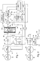
- an apparatus for measuring the moisture content of grain and determining crop yield comprises an RF transmitting means 10, a receiver circuit means 12 and a controller or processor means 14.
- the RF transmitting means 10 comprises an RF source 16 for continuously producing a measurement signal in the frequency range of about 1-10 GHz, a signal splitter 18, and a transmit antenna 20.
- the measurement signal output of RF source 16 is connected to the signal splitter 18 and one output of the signal splitter is applied to the transmit antenna 20 through a PIN diode 22.
- a receive antenna 24 drives the receiver circuit means 12.
- the antennas 20, 24 are disposed on opposite sides of a closed conveyor chute 26 which comprises a part of the grain flow path in a grain harvester.
- the chute 26 is made of a low dielectric plastic material, or is provided with windows of such a material, so as to have minimal effect on the RF signals as they pass through it.
- an interrupted flyte auger moves the grain through chute 26.
- the auger flyte is interrupted so that grain may accumulate and completely fill chute 26 in the region between antennas 20, 24, thereby providing a more uniform density of the grain through which the signal from transmit antenna 20 passes.
- the receiver circuit means 12 includes a quadrature demodulator 28 and, as illustrated in Figure 1, a gain control means such as a controllable amplifier 30 connected between the receive antenna 24 and one input of the demodulator.
- the output of signal splitter 18 is connected to a second input of the demodulator via a lead 32 so as to apply to the demodulator a reference signal which is in phase with the signal applied to transmit antenna 20.
- the demodulator may, for example, be a type MIQ64M5-2 quadrature demodulator commercially available from Loral Corporation, Eagan MN.
- the demodulator produces two time varying output voltages I and Q where I and Q represent the magnitude of the output signal from amplifier 30 measured at 0° and 90° of the reference signal on lead 32.
- the signals I and Q provide an indication of the attenuation and phase shift of a measurement signal as the signal is propagated over the measurement signal path extending from splitter 18 to antenna 20, through the grain in chute 26, and from the antenna 24 to demodulator 28.
- the attenuation A of the measurement signal is (I 2 +Q 2 ) 1/2 volts and the tangent of the phase shift ⁇ is Q/I.
- the controller or signal processor means 14 comprises a processor 34, an operator's control panel 36 and an alphanumeric display 38.
- the control panel and display are located near the operator's seat in the harvester so that the operator may conveniently enter control commands or data into the processor and observe data and messages generated by the processor.
- the processor 34 may be a conventional programmable microprocessor having ROM, RAM and EEPROM memories as well as analog to digital (ADC) and digital to analog (DAC) conversion circuits.
- ADC analog to digital
- DAC digital to analog
- the means for sensing grain speed comprises a doppler transmit/receive antenna 40 connected to a doppler transceiver 42.
- the output signal F from transceiver 42 and the output signals I and Q from demodulator 28 are all applied to the ADC circuits of the processor.
- the processor 34 operates during measurement intervals to repetitively sample the signals Q, I and F. From signals I, Q and F the processor determines grain moisture content, bulk density and yield. Intermittently, and while grain may be flowing through chute 26, the processor executes a calibrate routine and, if adjustment is necessary, sets the control voltage applied to the gain circuit 30 over lead 48 during subsequent measurement intervals. For this purpose, the DAC circuits of processor 34 produce output signals on leads 44, 46 and 48.
- Processor 34 with its DAC circuits comprise a means for selectively applying a bias current to the PIN diode 22.
- the diode may, for example, be a Hewlett-Packard type 5082-3340 calibrated PIN diode attenuator. Calibration data with high accuracy, traceable to the National Institute of Standards and Technology, are available with these devices from the manufacturer. When zero or reverse bias is applied to the diode it exhibits a very high resistance, introducing a known attenuation into the measurement signal path. When a forward bias is applied to the diode its resistance drops to practically zero, actually to a value less than one ohm.
- the RF isolation circuit 50 serves to isolate the RF output of splitter 18 from the processor 34.
- the inductances L 1 , L 2 serve as chokes to block the RF signal.
- Capacitors C 1 , C 2 and C 3 act to filter any of the RF signal passing through the inductances to prevent it from reaching the processor.
- the processor 34 produces signals on leads 44 and 46 to forward bias diode 22 so that it introduces no resistance or loss into the measurement signal path.
- the continuous output signal from RF source 16 is split by splitter 18 and applied to transmit antenna 20 and demodulator 28.
- the measurement signal is transmitted through the grain flowing in chute 26 where it is attenuated and shifted in phase to a degree dependent on the internal moisture content of the kernels of grain and the density of the grain.
- the phase shifted and attenuated measurement signal is amplified by gain control means 30 and applied to demodulator 28 which in turn produces the time varying voltage signals I and Q that are applied to the ADC circuits of processor 34.
- the diode 22 and gain control means 30 do not have to be located in the circuit positions shown in Figure 1. Either of these elements may be located anywhere in the measurement signal path downstream of the signal source 16 and upstream of demodulator 28.
- Figure 3 illustrates a routine executed by processor 34 to calculate grain moisture content and yield and, in accordance with the present invention, calculate a correction factor for calibrating or adjusting the gain of the measurement signal path.
- the routine is executed periodically at intervals of 10 ms but this interval is not critical.
- steps 100-108 are carried out to calculate moisture content and yield.
- steps 109-118 are carried out to develop a calibration factor for adjusting the gain in the measurement signal path, or produce a message for the operator regarding the condition of the measurement system.
- Step 101 computes the phase shift ⁇ and attenuation A imposed on the measurement signal as it passes over the measurement signal path and through the grain in chute 26.
- Step 102 converts the attenuation to an equivalent decibel loss dB m .
- Step 103 obtains from the processor memory the grain coefficients required to calculate grain moisture content.
- the kernels of different grains such as wheat, corn, etc. and different varieties of the same grain, such as soft and hard red winter wheat, exhibit different physical characteristics which must be taken into account in determining the moisture content of the grain.
- a look-up table is provided in the non-volatile memory in processor 34 and this table stores constants which are used in computing the moisture content.
- the operator Prior to initiation of a harvesting operation, the operator enters through control panel 36 an indication of the type/variety of grain to be harvested. At step 103, this indication is used to address the look-up table to obtain the constants to be used in calculating the moisture content and bulk density.
- the processor 34 calculates the moisture content (MC) and the bulk density using the measured values of attenuation and phase shift and the appropriate constants obtained from the look-up table.
- the prior art discloses many experimentally developed equations for computing grain moisture content and bulk density from the measured phase shift and attenuation imparted to an RF signal as it passes through grain.
- the calculations of moisture content and bulk density may be carried out according to the equations of Kraszewski and Nelson as set forth in Canadian Agricultural Engineering, Vol. 34, No. 4, pgs. 327-335 (1992).
- the calculations of moisture content and bulk density are not, per se, a part of the present invention and need not be discussed further.
- Step 106 determines the incremental yield (IYIELD). That is, at step 106 the processor determines the crop yield in the interval of time elapsing between consecutive executions of step 106.
- IYIELD BD * F * K 1 * K 2 where BD is the bulk density calculated at step 105, F is the velocity of grain flow through chute 26, K 1 is the cross-sectional area of the interior of chute 26 and K 2 is the time between consecutive executions of step 106.
- IYIELD is added to total yield (TYIELD).
- TYIELD represents the total crop yield or total crop processed since the start of the harvesting operation.
- steps 100-107 sample and convert the analog output signals Q, I and F from demodulator 28 and transceiver 42 to digital values, determine the phase shift ⁇ and attenuation A of the measurement signal, compute the moisture content and bulk density of the grain, and from the bulk density determine the total crop yield.
- calibration is carried out once each second.
- a timer (T) tolls the one-second intervals. T is incremented by 10 ms each time before step 108 is executed and the value in T is tested to determine if it represents one second. If one second has not passed the processor bypasses calibration steps 109-118 and exits the routine.
- timer T holds a value representing one second when it is tested at step 108, the timer is reset to begin tolling another one-second interval and the processor 34 advances to step 109 to perform a calibration.
- step 108 entirely so that the processor performs a calibration following each measurement. In this case, the step 108 is eliminated and the routine moves from step 107 directly to step 109
- the processor 34 carries out a calibration by reverse biasing PIN diode 22, measuring the actual attenuation of the measurement signal with the resistance of the diode in the measurement signal path, and determining the difference between the actual attenuation and the expected attenuation. Assuming the PIN diode 22 is a 20dB attenuator, the expected attenuation is assumed to be 20dB greater than the attenuation dB m determined at steps 100-102 immediately prior to insertion of the diode resistance into the measurement signal path. Although grain may, or may not be flowing, this assumption is quite accurate because the measurement of attenuation for calibration purposes always takes place in a matter of microseconds after steps 100-102 are executed.
- the processor sets outputs so that the DAC circuits produce output signals on leads 44, 46 to reverse bias PIN diode 22.
- the resistance of the PIN diode increases to a known value, thus introducing into the measurement signal path a resistance which should produce a known expected attenuation of the measurement signal if the gain of the measurement signal path is properly adjusted.
- the processor 34 samples the signals I and Q (step 110) while the PIN diode is still reverse biased, and from I and Q computes the actual attenuation A a (step 111).
- Processor 34 next determines the difference between the expected attenuation and the actual attenuation resulting from insertion of the PIN diode resistance into the measurement signal path.
- the actual attenuation value A a calculated at step 111 is expressed in volts and this value is converted (step 112) to the equivalent actual loss dB a in decibels.
- the actual loss dB a should be 20dB greater than the loss dB m determined at step 102.
- the processor subtracts from the actual attenuation dB a the sum of 20dB plus the attenuation dB m to obtain the difference dB e between the actual attenuation and the expected attenuation resulting from insertion of the diode resistance into the measurement signal path.
- the value dB e is used to adjust the gain of the measurement signal path so that, assuming no further changes in the measurement signal path, the value dB e will be zero the next time a calibration is carried out. However, the value dB e cannot be used directly to set the output signal on lead 48 to control the gain.
- the processor 34 is already applying a gain adjustment signal to amplifier 30 as a result of prior calibrations which developed prior difference values dB e .
- a correction factor CF representing the algebraic sum of these prior difference values is stored in memory. Step 113 adds dB e to CF and the result is saved for use during the next calibration.
- the value CF is used to set the magnitude of the gain adjustment signal applied to amplifier 30 over lead 48. However, before the gain adjustment signal is set, the value CF is checked to determine its magnitude. At step 114, the value of CF is checked to see if it represents an attenuation greater than 60. If so, it is probably a result of a circuit failure. At step 115 the processor sets an output message which is applied to display 38 to inform the operator. An audible alarm may also be sounded to call the operator's attention to the error.
- step 116 is executed to determine if CF is greater than 5. If CF is greater than 5, it is an indication that some maintenance should be performed such as cleaning dirt/moisture from the region between the antennas 20, 24. In this case an appropriate message is sent to display 38 (step 117) and an audible alert is sounded.
- step 116 determines that CF is no greater than 5
- the value of CF is used (step 118) to set an output signal to the amplifier 30 to thereby adjust the gain of the measurement signal path.
- CF which is in terms of decibels, is used to access a conversion table. The resulting output value from the conversion table is converted to an analog signal by the ADC circuits and the analog signal is applied over lead 48 to the amplifier.
- the resistance of PIN diode 22 may be removed from the measurement signal path at any time after I and Q are sampled at step 110 by placing signals on leads 44, 46 to forward bias the diode.
- Figure 1 illustrates the invention in a specific moisture/yield monitoring system
- the invention is equally suitable for use in other systems such as, for example, those systems wherein the signal from the receive antenna 24 is split and applied in parallel to a phase comparator and an amplitude comparator for comparison with the reference signal.
- an attenuator 60 calibrated to a traceable standard may be connected in the measurement signal path and selectively switched into, or out of, the path by a suitable switching means 62 illustrated as a PIN diode.
- a suitable switching means 62 illustrated as a PIN diode.
- the diode When the diode is forward biased, the measurement signal flows through the diode and the attenuator is removed from the signal path.
- the diode When the diode is reverse biased it blocks the measurement signal path and the attenuator is electrically inserted into the signal path.
- switching means 62 may be a pair of electronic switches or even a manual switch with contacts in series with attenuator 60.
- the bias voltage for biasing the PIN diode 22 or 62 need not come from the processor 34.
- a manual switch 64 may be provided for selectively connecting a source of bias voltage to the diode.
- Output lead 66 from the switch may be connected to the processor 34 and, in Figure 3, step 108 is replaced by a step in which actuation of switch 64 is sensed.
Landscapes
- Physics & Mathematics (AREA)
- Electromagnetism (AREA)
- Health & Medical Sciences (AREA)
- Life Sciences & Earth Sciences (AREA)
- Chemical & Material Sciences (AREA)
- Analytical Chemistry (AREA)
- Biochemistry (AREA)
- General Health & Medical Sciences (AREA)
- General Physics & Mathematics (AREA)
- Immunology (AREA)
- Pathology (AREA)
- Investigating Or Analyzing Materials By The Use Of Electric Means (AREA)
Applications Claiming Priority (2)
| Application Number | Priority Date | Filing Date | Title |
|---|---|---|---|
| US744250 | 1996-11-05 | ||
| US08/744,250 US5708366A (en) | 1996-11-05 | 1996-11-05 | Microwave moisture/yield monitor with calibration on-the-go |
Publications (2)
| Publication Number | Publication Date |
|---|---|
| EP0840108A2 true EP0840108A2 (de) | 1998-05-06 |
| EP0840108A3 EP0840108A3 (de) | 1998-07-01 |
Family
ID=24992034
Family Applications (1)
| Application Number | Title | Priority Date | Filing Date |
|---|---|---|---|
| EP97203304A Withdrawn EP0840108A3 (de) | 1996-11-05 | 1997-10-24 | Mikrowellenmessgerät für die Feuchtigkeit/den Ertrag mit on-line Kalibrierung |
Country Status (2)
| Country | Link |
|---|---|
| US (1) | US5708366A (de) |
| EP (1) | EP0840108A3 (de) |
Cited By (2)
| Publication number | Priority date | Publication date | Assignee | Title |
|---|---|---|---|---|
| GB2359630A (en) * | 2000-02-26 | 2001-08-29 | Frank Thompson | Measurement of moisture content using microwave radiation |
| CN102759535A (zh) * | 2011-04-27 | 2012-10-31 | 航天信息股份有限公司 | 基于无线射频识别技术的检测粮食水分含量的装置及方法 |
Families Citing this family (22)
| Publication number | Priority date | Publication date | Assignee | Title |
|---|---|---|---|---|
| US6025724A (en) * | 1997-11-20 | 2000-02-15 | Malcam Ltd. | Device and method for determining the moisture content of packaged material |
| JPH10111260A (ja) * | 1996-08-13 | 1998-04-28 | Satake Eng Co Ltd | 穀物加水制御方法及びその装置 |
| US5939888A (en) * | 1997-08-26 | 1999-08-17 | New Holland North America, Inc. | Digital method and apparatus for monitoring moisture content |
| JP4172002B2 (ja) | 1999-08-24 | 2008-10-29 | 株式会社サタケ | 循環式穀物乾燥機 |
| US6208255B1 (en) | 1999-10-20 | 2001-03-27 | Larry M. Conrad | Non-resonant electromagnetic energy sensor |
| US6346888B1 (en) * | 1999-10-20 | 2002-02-12 | Larry M. Conrad | Non-resonant electromagnetic energy sensor |
| US6820459B2 (en) * | 2002-09-18 | 2004-11-23 | Deere & Company | Automatic mass-flow sensor calibration for a yield monitor |
| ES2675393T3 (es) | 2010-12-22 | 2018-07-11 | Precision Planting Llc | Métodos, sistemas y aparatos para monitorizar rendimiento y vehículo |
| CN102759546B (zh) * | 2011-04-27 | 2013-12-11 | 航天信息股份有限公司 | 基于无线射频识别的在线检测粮食水分含量的装置及方法 |
| DE102011100244A1 (de) * | 2011-05-02 | 2012-11-08 | Mso Messtechnik Und Ortung Gmbh | Verfahren zur Messung eines leitungsgeführten Gutstroms mittels Microwellen, Sensoranordnung und Vorrichtung mit einer Sensoranordnung |
| AR090390A1 (es) | 2011-08-10 | 2014-11-12 | Prec Planting Llc | Sistema, metodo y aparato para monitoreo de rendimiento de cultivos |
| US9127972B2 (en) | 2011-09-28 | 2015-09-08 | The Board Of Trustees Of The University Of Illinois | Self-calibrating mass flow sensor system |
| CN102721709A (zh) * | 2012-07-05 | 2012-10-10 | 长春市龙应科技开发有限公司 | 一种基于微波技术的粮食含水率检测装置及检测方法 |
| WO2015048499A1 (en) * | 2013-09-27 | 2015-04-02 | John Earl Acheson | Yield monitor calibration method and system |
| US9645006B2 (en) * | 2014-06-27 | 2017-05-09 | Deere & Company | Calibration of grain mass measurement |
| US10863672B2 (en) * | 2017-11-06 | 2020-12-15 | Deere & Company | Radio frequency measurement device for measuring harvested agricultural material |
| US10871458B2 (en) * | 2017-11-06 | 2020-12-22 | Deere & Company | Radio frequency measurement device for measuring grain loss |
| PL423766A1 (pl) * | 2017-12-07 | 2019-06-17 | Uniwersytet Warmińsko-Mazurski w Olsztynie | Urządzenie do pomiaru wilgotności zboża |
| US12644848B2 (en) | 2019-10-14 | 2026-06-02 | Deere & Company | System and method for terahertz frequency object and crop contamination and constituent detection and handling |
| US11696529B2 (en) | 2019-10-14 | 2023-07-11 | Deere & Company | Radio frequency grain mass and constituent measurement systems for combine harvesters |
| US12575496B2 (en) | 2019-10-14 | 2026-03-17 | Deere & Company | System and method for terahertz frequency crop contamination detection and handling |
| US12063885B2 (en) | 2020-11-03 | 2024-08-20 | Deere & Company | Kernel-level grain monitoring systems for combine harvesters |
Family Cites Families (6)
| Publication number | Priority date | Publication date | Assignee | Title |
|---|---|---|---|---|
| DE1498988C3 (de) * | 1962-12-30 | 1974-06-12 | Shinichi Urawa Sasaki (Japan) | Verfahren zum Messen des Feuchtigkeitsgehaltes eines körnigen Gutes |
| US3644826A (en) * | 1967-04-03 | 1972-02-22 | Industrial Nucleonics Corp | Moisture-measuring system using microwave and nucleonic measurements |
| US5103181A (en) * | 1988-10-05 | 1992-04-07 | Den Norske Oljeselskap A. S. | Composition monitor and monitoring process using impedance measurements |
| US5001434A (en) * | 1989-04-10 | 1991-03-19 | Texaco Inc. | Variable mode microwave water cut monitor and method |
| US5644244A (en) * | 1991-06-21 | 1997-07-01 | Texaco Inc. | Method for analyzing a petroleum stream |
| US5576974A (en) * | 1994-04-15 | 1996-11-19 | Texaco Inc. | Method and apparatus for determining watercut fraction and gas fraction in three phase mixtures of oil, water and gas |
-
1996
- 1996-11-05 US US08/744,250 patent/US5708366A/en not_active Expired - Lifetime
-
1997
- 1997-10-24 EP EP97203304A patent/EP0840108A3/de not_active Withdrawn
Cited By (3)
| Publication number | Priority date | Publication date | Assignee | Title |
|---|---|---|---|---|
| GB2359630A (en) * | 2000-02-26 | 2001-08-29 | Frank Thompson | Measurement of moisture content using microwave radiation |
| CN102759535A (zh) * | 2011-04-27 | 2012-10-31 | 航天信息股份有限公司 | 基于无线射频识别技术的检测粮食水分含量的装置及方法 |
| CN102759535B (zh) * | 2011-04-27 | 2014-12-17 | 航天信息股份有限公司 | 基于无线射频识别技术的检测粮食水分含量的装置及方法 |
Also Published As
| Publication number | Publication date |
|---|---|
| EP0840108A3 (de) | 1998-07-01 |
| US5708366A (en) | 1998-01-13 |
Similar Documents
| Publication | Publication Date | Title |
|---|---|---|
| US5708366A (en) | Microwave moisture/yield monitor with calibration on-the-go | |
| US5939888A (en) | Digital method and apparatus for monitoring moisture content | |
| US5934997A (en) | Method of determining the moisture content of grain | |
| US6463794B1 (en) | Method and device for non-invasively determining moisture content and uniformity of solid plant matter during on-line drying or cooling forced-air treatment | |
| US5716272A (en) | Moisture/yield monitor grain simulator | |
| EP0536080B1 (de) | Verfahren zur Durchflussmessung. | |
| EP0064198B1 (de) | Apparat zur Messung des Rauschfaktors und der verfügbaren Verstärkung | |
| US9537584B2 (en) | Phased array device and calibration method therefor | |
| US5837906A (en) | Apparatus and method for measuring the real-time volumetric flow rate of grain in a field harvester using acoustical transducers | |
| EP0357533B1 (de) | Gerät zum Wiegen und zur Grössenmessung von Personen | |
| EP0802420A2 (de) | Impedanzmesseinrichtung | |
| EP3479673B1 (de) | Messvorrichtung zur messung von kornverlust | |
| AU2002301044B2 (en) | Microwave flow sensor for a harvester | |
| US5917315A (en) | Receiver for spectrum analysis | |
| KR100421452B1 (ko) | 벌크물질의습기를연속검출하는방법과장치 | |
| US6389884B1 (en) | Device and method for measuring the moisture of crop material in agricultural machines | |
| US7231308B2 (en) | Test system dynamic range extension through compression compensation | |
| US6853176B2 (en) | Power measurement apparatus and method therefor | |
| WO1996008888A1 (en) | Method and apparatus for temperature compensation in a time division multiplex receiver | |
| JP3037882B2 (ja) | 放出された熱ノイズの測定により物体の温度を決定するための放射計および、この放射計を利用した測定方法 | |
| CA2700096A1 (en) | A system and method for determining moisture content in a bale of hay | |
| EP1547242B1 (de) | Einrichtung und verfahren zur bestimmung des pegels eines eingangssignals, das an ein empfangssystem angelegt werden soll | |
| US4875940A (en) | Massecuite supersaturation monitor | |
| EP0874245A1 (de) | Verfahren und Gerät zur Bestimmung der Rauschcharakteristiken elektrischer Geräte | |
| US6414310B1 (en) | Automatic control circuit for infrared detectors |
Legal Events
| Date | Code | Title | Description |
|---|---|---|---|
| PUAI | Public reference made under article 153(3) epc to a published international application that has entered the european phase |
Free format text: ORIGINAL CODE: 0009012 |
|
| AK | Designated contracting states |
Kind code of ref document: A2 Designated state(s): DE DK FR GB IT |
|
| PUAL | Search report despatched |
Free format text: ORIGINAL CODE: 0009013 |
|
| AK | Designated contracting states |
Kind code of ref document: A3 Designated state(s): AT BE CH DE DK ES FI FR GB GR IE IT LI LU MC NL PT SE |
|
| 17P | Request for examination filed |
Effective date: 19981210 |
|
| AKX | Designation fees paid |
Free format text: DE DK FR GB IT |
|
| RBV | Designated contracting states (corrected) |
Designated state(s): DE DK FR GB IT |
|
| RAP1 | Party data changed (applicant data changed or rights of an application transferred) |
Owner name: CNH BELGIUM N.V. |
|
| 17Q | First examination report despatched |
Effective date: 20070830 |
|
| STAA | Information on the status of an ep patent application or granted ep patent |
Free format text: STATUS: THE APPLICATION IS DEEMED TO BE WITHDRAWN |
|
| 18D | Application deemed to be withdrawn |
Effective date: 20080311 |