EP0840246B1 - Dispositif de contact pour cartes SIM - Google Patents
Dispositif de contact pour cartes SIM Download PDFInfo
- Publication number
- EP0840246B1 EP0840246B1 EP97119047A EP97119047A EP0840246B1 EP 0840246 B1 EP0840246 B1 EP 0840246B1 EP 97119047 A EP97119047 A EP 97119047A EP 97119047 A EP97119047 A EP 97119047A EP 0840246 B1 EP0840246 B1 EP 0840246B1
- Authority
- EP
- European Patent Office
- Prior art keywords
- sim
- card
- card reader
- cover
- reader according
- Prior art date
- Legal status (The legal status is an assumption and is not a legal conclusion. Google has not performed a legal analysis and makes no representation as to the accuracy of the status listed.)
- Expired - Lifetime
Links
Images
Classifications
-
- G—PHYSICS
- G06—COMPUTING OR CALCULATING; COUNTING
- G06K—GRAPHICAL DATA READING; PRESENTATION OF DATA; RECORD CARRIERS; HANDLING RECORD CARRIERS
- G06K7/00—Methods or arrangements for sensing record carriers, e.g. for reading patterns
- G06K7/0013—Methods or arrangements for sensing record carriers, e.g. for reading patterns by galvanic contacts, e.g. card connectors for ISO-7816 compliant smart cards or memory cards, e.g. SD card readers
- G06K7/0021—Methods or arrangements for sensing record carriers, e.g. for reading patterns by galvanic contacts, e.g. card connectors for ISO-7816 compliant smart cards or memory cards, e.g. SD card readers for reading/sensing record carriers having surface contacts
-
- G—PHYSICS
- G06—COMPUTING OR CALCULATING; COUNTING
- G06K—GRAPHICAL DATA READING; PRESENTATION OF DATA; RECORD CARRIERS; HANDLING RECORD CARRIERS
- G06K13/00—Conveying record carriers from one station to another, e.g. from stack to punching mechanism
- G06K13/02—Conveying record carriers from one station to another, e.g. from stack to punching mechanism the record carrier having longitudinal dimension comparable with transverse dimension, e.g. punched card
- G06K13/08—Feeding or discharging cards
- G06K13/085—Feeding or discharging cards using an arrangement for locking the inserted card
- G06K13/0862—Feeding or discharging cards using an arrangement for locking the inserted card the locking arrangement being of the rotate-slide and lock type, such as, e.g. common in mobile phones
Definitions
- the invention relates to a contacting device generally for chip cards and especially for SIM cards.
- a contacting device can briefly be used as a card reader specifically referred to as a SIM card reader.
- a contacting device especially for a SIM (Subscriber Identity Modules).
- SIM Subscriber Identity Modules
- this contacting device is a provided as a contact carrier housing, and the SIM is enclosed by a cover or a housing part inserted SIM against contact elements arranged in the contact carrier pressed.
- Serve storage or articulation for storing the cover on the contact carrier.
- EP-A-0 131 410 shows a chip card reader with a contact carrier, with a lid and with storage devices on the contact carrier and on Lid to allow swivel movement between cover and contact carrier.
- the storage devices have a static bearing part on Contact carrier and a rotatable bearing part on Cover on and are outside one IC card arranged
- the FR-2696031 also shows like DE-36 42 424 a chip card reader or IC card reader where broad arrangements for the Storage devices of the lid are provided.
- SIM card readers are commonly used in phone devices used in so-called cell phones that are built as small as possible should be.
- a narrow width is intended and height of the SIM card reader can be provided.
- the overall height of the SIM card reader is inventively in particular by reducing the bearing locations provided storage devices limited in height, in particular by using an or several control curves for the guidance of the SIM card.
- the folding sliding lid because of the side positioned on the long sides of the card Bearings can be closed so that the card simply rotates or swivels (practical without moving the SIM card within the Lid) performs when locking, enables the invention provided, preferably on the storage devices trained control curve that the card at Swiveling the cover in its closed or contact position along this partly relatively flat control curve in a contact formed in the contact carrier moves, while moving the SIM card relative to the lid.
- the measures according to the invention are favorable External dimensions (in mm) of, for example, 30 x 17.2 x 2.5 realized, the card contacts when closing the lid the SIM card in the middle of the contact field Contact elements encounter what the already mentioned Control curve ensures. That is, through the control curve the SIM card is like this when you close the cover forced that the card contacts in the middle of the contact field of the contact elements hit. When closing the So the cover guides the SIM card through the control curve certain relative movement to the lid.
- a SIM card reader which a flat contact carrier forming a card holder has, on which a lid is pivotable by means of two bearing devices is stored.
- the two storage devices are essentially within the card width arranged.
- the storage devices are preferably inside the card width lying in the direction of the longitudinal extent the SIM card reader to the rear.
- the expression "to the rear” describes that the storage devices opposite one of the card holder formed stop for the rear edge of the card are offset, it should be noted that the SIM card in addition to two spaced longitudinal side edges two also has spaced shorter card edges, namely a leading edge and a trailing edge, the Front edge has a bevel.
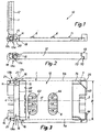
- FIGS. 1 to 5 An exemplary embodiment is described below with reference to FIGS. 1 to 5 described the invention.
- the invention is described using a SIM card reader, but is can also be used with a regular chip card reader.
- the SIM card reader 10 has a frame or contact carrier 11 in which a plurality of contact elements 6 are arranged, for example injected.
- a cover 12 by storage means rotatably mounted.
- the cover 12 serves to receive a SIM card 1.
- a (dotted shown) shaft-forming rails or Card guide parts provided.
- Cover 12 and contact carrier 11 are preferably each in one piece from plastic manufactured. It is also possible to remove the lid Shaping metal.
- the SIM card The SIM card.
- the SIM card 1 is shown in dashed lines in the drawings.
- the SIM card 1 has, cf. Fig. 3, a leading edge 2 with a bevel 3 and a rear edge 4 on. Side edges 5a and 5b are also provided.
- the SIM card does not have a contact field shown card contacts for contacting the also contact elements 6 arranged in a contact field.
- the storage means The storage means.
- the storage means by two spaced apart storage devices (or storage points) 13a and 13b (see FIG. 2).
- the two Bearing devices 13a and 13b are mirror images, so that in the following only the storage device 13a is described.
- the bearing devices 13a, 13b firstly allow the cover 12 to be pivoted relative to the contact carrier 11 about a pivot point or an axis of rotation 13c. After the cover 12 from the in Fig. 1 shown card insertion position by 90 ° in its Closed or contact position is pivoted, allow the bearing devices 13a, 13b also preferably one Shifting the lid 12 in Fig. 1 to the right in a Locking position for the cover 12, which is shown in Fig. 2nd is shown.
- the SIM card 1 remains in your already at the end of the pivoting movement of the lid 12 90 ° reached contact position with the contact elements 6th
- the storage devices 13a, 13b are located inside the width B of the SIM card 1, as you can easily in 3 and 4 recognizes.
- the bearing device 13a has one (Static) bearing part (bearing block) 14 on on the contact carrier 11 preferably in one piece with this educated.
- the bearing device 13a also has one (rotatable) bearing part. This has preferably the Shape of a pin 15 on the lid 12 and is preferred integrally formed with this.
- the pins 15 protrude arms 16 formed on the lid 12 perpendicular to the Card reader longitudinal axis 17 inwards (in the inserted State) in a recess formed in the bearing part 14 20.
- the recess 20 points two sections and namely a rotary recess 18 (Fig.
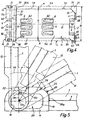
- control curve or control surface 25 The control curve or control surface 25.
- Each of the bearing parts 14 has one on its top Control curve (control or cam surface) 25, in particular a flat surface 26 and adjoining it 5 to the left in FIG. 5 and a swivel radius surface has a swivel radius surface 27 on the right.
- the swivel radius area 27 ends immediately above contact surfaces (or contact edges) 30a and 30b by the bearing parts 14 are formed.
- These contact surfaces 30a, 30b form for the trailing edge 4 together with those to be described Contact edges or surfaces for the leading edge 2 and their bevel 3 a card holder 7.
- the card holder 7 defines the contact position for the SIM card.
- the contact carrier 11 has a flat plate part 31, on the left narrow side in Fig. 4 the spaced Bearing blocks 14 are provided.
- a flat plate part 31 In alignment with the Contact surfaces 30a, 30b is preferably another contact surface 32 provided by one piece with the Plate part 31 formed web 33 is formed.
- the Web 33 protrudes from the top of plate part 31 slightly upwards and preferably has a height of approximately the magnitude of the thickness of the SIM card 1.
- the height of the But web 33 is preferably not as high as the height the flat surface 26.
- the contact surface 32 Opposed to the contact surface 32 are more, above System edges or contact surfaces for the SIM card 1 is provided to form the card holder 7.
- one forms from the plate part 31 upwards protruding projection 35 an inclined ania surface 36 for the bevel provided on the SIM card 3.
- a web 40 which is perpendicular to the longitudinal axis 17 of the SIM card reader 10 runs, a contact surface 41. Aligned with the web 40 but at a distance from it and also perpendicular to the longitudinal axis 17 of the SIM card reader a further web 44 is provided running, the one contact surface 45 for the leading edge 2 of the SIM card 1 forms.
- Another web 46 extends preferably starting from the web 44 parallel to the longitudinal axis 17 of the SIM card reader towards the contact surface 32, preferably only over a short distance, and forms a lateral contact surface 47 for a small one Part of the side edge 5a and a part that is adjacent to the front edge 2.
- the contact surface 47 is completed the card holder 7.
- Projection 35, webs 40, 44 and 46 are, so to speak, on tongues 48, 49 of the flat plate part 31 and In between form a recess 50 into which ends of the contact elements 6 protrude.
- the tongues 48, 49 form with their tops an extension of the top of the flat plate part 31 formed plane or surface.
- Longitudinal edges 57, 58 of the flat plate part 31 are opposite the side surfaces 76 and 77 (Fig. 4) of the bearing parts 14 and opposite the side surface 78 of the projection 35 and the contact surface 47 preferably around the offset the same distance A to the longitudinal axis 17 of the reader.
- the width b of the plate part 31 is therefore smaller than that Width B of the card 1. This creates space for the accommodation the arms 16 and the side card guide parts cover 12.
- the plate part 31 protrudes from the longitudinal side edge 57 a guide surface 55 and from the long side edge 58 protruding a guide tongue 56.
- guide surface 55 and Guide tongue 56 work with complementarily trained Surfaces on the lid 12 together to provide good guidance the translational movement of the cover 12 from the contact position of the lid 12 in the locked position of the To reach cover 12.
- the contact elements 6 In the top of the cover 12 are in the area of the contact ends the contact elements 6 have oval openings 63, 64 provided and that in the locking position Cover 12.
- cover 12 already through the passage openings 21 in the rotary recesses 18 with its Pin 15 is inserted and about that shown in Fig. 1 Occupies the card insertion position, the SIM card 1 in a shaft formed in the cover 12 is used.
- cover 12 need not necessarily be that shown in FIG. 1 Take vertical position, but can already have a slightly inclined position, for example the 5 shown in the middle position.
- After inserting the Card 1 in the cover 12 sits the card 1 with its rear Edge on the control cam (or cam surface) 25 of the two bearing parts 14.
- the lid 12 is therefore rear (or below in Fig. 1) not closed, but forms a kind of recess 28 in the lid because of the arms 16 12th
- the storage devices according to the invention 13a, 13b in particular the stationary bearing blocks or Bearing parts 14 within the width B of the used SIM card 1 are arranged.
- the bearing blocks 14 are opposite of the contact surface 32 offset to the left in FIG. 3.
- the locking position of the cover 12 is in 3 and 4 by the dash-dotted line 23 and is immediately adjacent but in Fig. 3rd and 4 offset to the left opposite the contact edge 32, while the dot-dash line illustrating the axis of rotation 13 Line shifted further to the left opposite the locking position 23 of the bearing pin 15 is provided.
- the control curve 25 ensures that despite this arrangement a safe transfer which is a relative movement with respect to the cover 12 executing card 1 at the transition from the insertion position is reached in the contact position.
- Card 1 can hit at the point when inserting on the control cam 25, where the arrow R1 ends.
- the map runs along flat surface 26 for example to the position marked with R2.
- R2> R1 there is a relative movement for the card 1.
- the arrow R3 indicates that when pivoting further the cover 12 a further relative displacement for card 1 until finally card 1 in the card holder 7 arrives.
- the control curve would have to go through the circular arc 75 in FIG. 5 indicated cam or curve course can be provided, but which would result in a large overall height.
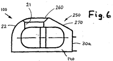
- FIG. 6 shows a further preferred exemplary embodiment of a SIM card reader 100 in a view similar to the illustration in FIG. 5 relating to the SIM card reader 1.
- the bearing part 140 differs from the bearing part 14 in that the control curve 250 of the bearing part 140 is modified.
- the swivel radius 27 of the bearing part 14 is replaced by an inclined surface 270.
- the area 260 corresponding to the flat surface 26 in FIG. 5 is shortened and ends approximately (on the right in FIG. 6) adjacent to the passage opening 21 and then essentially directly into the To pass over inclined surface 270.
- the inclined surface 270 thus extends obliquely downwards to the upper end of the contact surface 30a.
- the inclined surface 270 is preferably flat and of course provided on the two bearing parts 140.
- the swivel radius surface 22 is provided in FIG. 6 and in FIG. 5.
- the invention relates to a smart or SIM card reader with a contact carrier having contact elements, the bearing point on the contact carrier being within the outline of the smart or SIM card used in the smart or SIM card reader. It should be noted that the objects and advantages of the invention can be achieved by any improvements, changes and modifications that are covered by the following summary of the invention and the claims.
Landscapes
- Engineering & Computer Science (AREA)
- Physics & Mathematics (AREA)
- General Physics & Mathematics (AREA)
- Theoretical Computer Science (AREA)
- Artificial Intelligence (AREA)
- Computer Vision & Pattern Recognition (AREA)
- Coupling Device And Connection With Printed Circuit (AREA)
- Conveying Record Carriers (AREA)
Claims (28)
- Lecteur de cartes SIM comportant un support de contacts (11) présentant des éléments de contact (6), un couvercle (12) pour recevoir une carte SIM (1) ayant deux bords longitudinaux espacés (5a, 5b) et deux bords avant et arrière espacés (2, 4), avec de préférence deux dispositifs à palier (13a, 13b) situés sur le support de contacts et le couvercle pour rendre possible un mouvement de pivotement entre le couvercle et le support de contacts, dans lequel chacun des dispositifs à palier (13a, 13b) présente une partie de palier statique (14, 140) située sur le support de contacts (11) et une partie de palier mobile (15) située sur le couvercle (12), et dans lequel les deux dispositifs à palier (13a, 13b) se trouvent dans un espace correspondant à la largeur (B) de la carte SIM pouvant être insérée dans le lecteur de cartes SIM.
- Lecteur de cartes SIM selon la revendication 1, dans lequel les dispositifs à palier (13a, 13b) sont situés en face de la ou des surfaces de positionnement (32, 30a, 30b) au voisinage de l'extrémité du support de contacts (11).
- Lecteur de cartes SIM selon la revendication 1, dans lequel une partie de palier (14, 140) située sur le support de contacts comporte une came de commande (25, 250), de sorte que la carte (1) est conduite dans un réceptacle de carte lors de la fermeture du couvercle (12).
- Lecteur de cartes SIM selon l'une quelconque des revendications précédentes, dans lequel le couvercle (12) est monté à palier sur le support de contacts (11) en vue d'un mouvement de rotation et d'un mouvement de translation.
- Lecteur de cartes SIM selon l'une des revendications 1 à 3, dans lequel le couvercle est mobile d'une position de réception de carte à une position de contact de carte avec les éléments de contact (6), le couvercle lui-même ou une partie associée au couvercle pouvant ensuite être déplacé dans une position dans laquelle la carte SIM est maintenue dans sa position de contact et le couvercle verrouillé.
- Lecteur de cartes SIM selon l'une quelconque des revendications précédentes, dans lequel les dispositifs à palier (13a, 13b) se trouvant dans un espace correspondant à la largeur de la carte garantissent que les contacts de carte rencontrent les zones médianes des éléments de contact (6) grâce à une came de commande (25), la carte devant effectuer, lors de la fermeture du couvercle (12), un mouvement relatif par rapport au couvercle du fait de la came de commande et étant ainsi placée dans un réceptacle de carte du support de contacts.
- Lecteur de cartes SIM selon l'une quelconque des revendications précédentes, dans lequel les parties de palier sont conçues pour limiter la hauteur du lecteur de carte SIM et présentent, à leur surface supérieure, une surface sensiblement plane (26) passant à une surface courbe (27) vers le réceptacle de carte.
- Lecteur de cartes SIM selon la revendication 6 ou 7, dans lequel le réceptacle de carte situé sur le support de contacts (11) est réalisé par des surfaces de positionnement (30a, 30b, 36, 41, 45, 47).
- Lecteur de cartes SIM selon l'une des revendications 3 à 8, dans lequel les parties de palier (14, 140) comportent en partie haute des ouvertures d'admission (21) pour permettre l'insertion des parties de palier du couvercle (12), réalisées en particulier comme des pivots (15).
- Lecteur de cartes SIM selon l'une quelconque des revendications précédentes, dans lequel la largeur du lecteur de cartes SIM au niveau des parties de palier (14) et au niveau du bord avant de la carte SIM (1) insérée correspond sensiblement à la largeur (B) de la carte SIM, tandis que le support de contacts (11) comportant la partie de plateau plane 31 intermédiaire présente une largeur réduite au moins de telle façon que les parties latérales du couvercle présentes pour la réception de carte viennent reposer dans ces évidements lorsque le couvercle est fermé, de façon que le couvercle ne présente aucun élargissement significatif du lecteur de cartes SIM par rapport à la largeur de la carte SIM.
- Lecteur de cartes SIM selon l'une quelconque des revendications précédentes, dans lequel le couvercle peut être verrouillé en position après déplacement de la carte SIM en position de contact, à l'aide de moyens additionnels prévus sur le couvercle.
- Lecteur de cartes SIM selon l'une des revendications 3 à 11, dans lequel la came de commande respectivement la surface de la came de commande (25) est prévue sur la partie supérieure des parties de palier (14) et présente une surface sensiblement plane (26) ainsi qu'une surface arrondie de pivotement (27, respectivement 22) située à la suite la surface plane (26) et de préférence des deux côtés, et dans lequel un réceptacle de carte (7) est formé par le support de contacts et comporte de préférence des surfaces de positionnement.
- Lecteur de cartes SIM selon l'une quelconque des revendications précédentes, dans lequel la carte SIM (1) est pour l'essentie maintenue dans sa position de contact au niveau du bord avant (2), du biseau (3) et du bord arrière (4) par des surfaces de positionnement (30a, 30b, 32, 36, 41, 45) du support de contact (11).
- Lecteur de cartes SIM selon l'une quelconque des revendications précédentes, dans lequel une surface de positionnement latérale (47) est prévue à proximité du bord avant (2).
- Lecteur de cartes SIM selon l'une quelconque des revendications précédentes, dans lequel, à proximité du bord avant, latéralement par rapport à la partie de plateau plane (31), sont prévues des surfaces de guidage (55) ou des languettes de guidage (56), et dans lequel, au niveau du bord avant, des moyens de verrouillage sont prévus sur la partie de plateau plane (31), en particulier sur des languettes (48, 49), ces moyens de verrouillage coopérant avec des moyens de verrouillage (70) situés sur le couvercle (12).
- Lecteur de cartes SIM selon l'une quelconque des revendications précédentes, dans lequel, au niveau du bord avant d'une carte disposée dans le réceptacle de carte, sont prévus, équipés de surfaces de positionnement pour la carte, une partie en saillie (35), un épaulement (40), un autre épaulement (44) et un épaulement (46) perpendiculaire à ce dernier.
- Lecteur de cartes SIM selon l'une quelconque des revendications précédentes, caractérisé en ce que, sur la face supérieure du couvercle (12), sont prévues des ouvertures (63, 64) permettant de voir la zone de contact des éléments de contact (6) quand aucune carte SIM n'est insérée.
- Lecteur de cartes SIM selon une des revendications 3 à 17, dans lequel la came de commande (250) située sur le côté supérieur de chaque bloc à palier (140) présente de préférence une surface sensiblement plane (260) se prolongeant en une surface oblique (270) vers l'extrémité supérieure du bord de positionnement (30a).
- Lecteur de cartes SIM selon la revendication 18, dans lequel la surface oblique (270) est plane.
- Lecteur de cartes SIM selon la revendication 18 ou 19, dans lequel la surface plane (260) est prévue au niveau de l'ouverture d'admission (21).
- Lecteur de cartes SIM selon l'une des revendications 18 à 20, dans lequel la surface plane (260) présente une longueur qui correspond sensiblement à la moitié du diamètre de l'ouvert d'admission (21).
- Lecteur de cartes SIM selon l'une des revendications 18 à 21, dans lequel une surface arrondie de pivotement (22) fait suite à la surface plane (260) du côté opposé à la surface inclinée (270).
- Lecteur de cartes SIM selon l'une quelconque des revendications précédentes, dans lequel la partie de palier mobile (15) est réalisée d'une seule pièce avec le couvercle.
- Lecteur de cartes SIM selon l'une quelconque des revendications précédentes, dans lequel la partie de palier statique (14) comporte un évidement (18) comprenant un évidement de pivotement (18) et un évidement d'arrêt (19).
- Lecteur de cartes SIM selon l'une quelconque des revendications précédentes, dans lequel des parties de guidage de la carte, des parties de palier mobiles (15) et des moyens de verrouillage (70) sont réalisés d'une seule pièce avec le couvercle (12) .
- Lecteur de cartes SIM selon l'une quelconque des revendications précédentes, dans lequel dans la partie de palier statique (14), des moyens de verrouillage (languettes 49) et des surfaces de positionnement (30a, 30b, 32, 26, 41, 45) sont réalisés d'une seule pièce avec le support de contacts (11).
- Lecteur de cartes SIM selon l'une quelconque des revendications précédentes, dans lequel le support de contacts présente une surface de guidage (55) et une languette de guidage (56), qui coopèrent avec des surfaces complémentaires situées sur le couvercle.
- Lecteur de cartes SIM selon l'une quelconque des revendications précédentes, dans lequel les deux dispositifs à palier (13a, 13b) sont disposés à distance l'un de l'autre et à proximité des surfaces latérales (76, 77) formées par le support de contact (11) .
Applications Claiming Priority (4)
| Application Number | Priority Date | Filing Date | Title |
|---|---|---|---|
| DE19645584 | 1996-11-05 | ||
| DE19645584 | 1996-11-05 | ||
| DE19734424A DE19734424C5 (de) | 1996-11-05 | 1997-08-08 | SIM-Kartenkontaktiervorrichtung |
| DE19734424 | 1997-08-08 |
Publications (4)
| Publication Number | Publication Date |
|---|---|
| EP0840246A2 EP0840246A2 (fr) | 1998-05-06 |
| EP0840246A3 EP0840246A3 (fr) | 2000-03-15 |
| EP0840246B1 true EP0840246B1 (fr) | 2003-09-17 |
| EP0840246B2 EP0840246B2 (fr) | 2011-03-16 |
Family
ID=26030989
Family Applications (1)
| Application Number | Title | Priority Date | Filing Date |
|---|---|---|---|
| EP97119047A Expired - Lifetime EP0840246B2 (fr) | 1996-11-05 | 1997-10-31 | Dispositif de contact pour cartes SIM |
Country Status (3)
| Country | Link |
|---|---|
| US (1) | US5996891A (fr) |
| EP (1) | EP0840246B2 (fr) |
| JP (1) | JP4142139B2 (fr) |
Families Citing this family (27)
| Publication number | Priority date | Publication date | Assignee | Title |
|---|---|---|---|---|
| GB2327791B (en) * | 1997-07-25 | 2001-03-21 | Nokia Mobile Phones Ltd | A data card connector |
| JPH11297415A (ja) | 1998-04-03 | 1999-10-29 | Molex Inc | カード用コネクタ |
| JP2957554B1 (ja) | 1998-05-18 | 1999-10-04 | 山一電機株式会社 | カードコネクタ |
| EP0965937B1 (fr) * | 1998-06-15 | 2006-08-09 | Molex Incorporated | Connecteur pour cartes à puces |
| DE69800330T2 (de) * | 1998-07-30 | 2001-05-17 | Molex Inc., Lisle | IC-Kartenverbinder |
| DE19850646A1 (de) * | 1998-11-03 | 2000-05-04 | Amphenol Tuchel Elect | Kartenanwesenheitsschalter für einen SIMLOCK |
| JP2000260537A (ja) * | 1999-02-16 | 2000-09-22 | Amphenol Tuchel Electronics Gmbh | スマートカードコネクタ |
| JP2000340280A (ja) * | 1999-05-31 | 2000-12-08 | Mitsumi Electric Co Ltd | メモリカード用コネクタ |
| FR2796763B1 (fr) * | 1999-07-23 | 2002-02-01 | Itt Mfg Enterprises Inc | Connecteur electrique pour carte a circuit(s) integre(s) comportant un commutateur de verrou du couvercle porte carte |
| ATE272866T1 (de) | 1999-07-26 | 2004-08-15 | Amphenol Tuchel Elect | Kontaktiereinrichtung |
| FR2799559B1 (fr) * | 1999-10-07 | 2001-12-07 | Valeo Securite Habitacle | Agencement pour la reception d'un support de donnees dans un dispositif d'echange de donnees comportant un support pivotant |
| US6646957B2 (en) * | 2000-02-16 | 2003-11-11 | Asulab S.A. | Telephone watch including a SIM card in its housing |
| DE10027131C2 (de) * | 2000-05-31 | 2003-03-27 | Amphenol Tuchel Elect | Aushebeleinrichtung für Deckel einer SIM-Kartenkontaktiereinrichtung |
| TW474466U (en) * | 2000-06-03 | 2002-01-21 | Hon Hai Prec Ind Co Ltd | Electronic card connector |
| US20040042323A1 (en) * | 2002-05-31 | 2004-03-04 | Masoud Moshayedi | Removable storage device |
| US20060270263A1 (en) * | 2002-11-19 | 2006-11-30 | Toshihisa Hirata | Memory card connector |
| TWM252147U (en) * | 2003-09-19 | 2004-12-01 | Hon Hai Prec Ind Co Ltd | Electrical card connector |
| TWM251345U (en) | 2003-09-30 | 2004-11-21 | Hon Hai Prec Ind Co Ltd | Electrical card connector |
| US6913479B1 (en) * | 2004-01-20 | 2005-07-05 | Cheng Uei Precision Industry Co., Ltd. | Electronic card connector |
| CN2746584Y (zh) * | 2004-08-10 | 2005-12-14 | 上海莫仕连接器有限公司 | 电子卡连接器 |
| DE102004063982A1 (de) * | 2004-11-09 | 2006-06-14 | Lumberg Connect Gmbh & Co. Kg | Kontaktiervorrichtung für eine Chipkarte, insbesondere für eine SIM-Karte |
| US7118419B1 (en) * | 2006-04-04 | 2006-10-10 | Cheng Uei Precision Industry Co., Ltd. | Foldable SIM card connector |
| TWM320779U (en) * | 2006-10-30 | 2007-10-11 | Hon Hai Prec Ind Co Ltd | Electrical card connector |
| US7270559B1 (en) * | 2006-11-09 | 2007-09-18 | Jess-Link Products Co., Ltd. | Electrical card connector including a locking mechanism |
| CN201029121Y (zh) * | 2007-03-05 | 2008-02-27 | 富士康(昆山)电脑接插件有限公司 | 电子卡连接器 |
| DE102007031047B4 (de) * | 2007-07-04 | 2010-09-09 | Amphenol-Tuchel Electronics Gmbh | Lesegerät für eine Microkarte |
| CN102738618B (zh) * | 2011-04-15 | 2015-02-04 | 索尼爱立信移动通讯有限公司 | 存储卡卡座、移动终端及存储卡的保护方法 |
Family Cites Families (29)
| Publication number | Priority date | Publication date | Assignee | Title |
|---|---|---|---|---|
| US4602351A (en) * | 1983-07-06 | 1986-07-22 | Tokyo Tatsuno Co., Ltd. | Device for reading and writing IC-external storage cards |
| DE3531318A1 (de) * | 1985-09-02 | 1987-03-05 | Allied Corp | Kontaktiereinrichtung fuer eine chip-karte |
| JPS62137689A (ja) * | 1985-12-11 | 1987-06-20 | Sharp Corp | Icカ−ド用情報処理装置 |
| DE3602668A1 (de) * | 1986-01-29 | 1987-07-30 | Allied Corp | Kontaktiereinrichtung fuer eine chip-karte |
| DE3618091C1 (fr) * | 1986-05-30 | 1987-09-10 | Allied Corp., Morristown, N.J., Us | |
| DE3625306A1 (de) * | 1986-07-25 | 1988-01-28 | Allied Corp | Kontaktiereinrichtung mit kartensicherung |
| JP2570286B2 (ja) † | 1987-03-31 | 1997-01-08 | 三菱電機株式会社 | Icカ−ドコネクタ |
| DE8817092U1 (de) * | 1988-03-25 | 1992-11-05 | Amphenol Corp., Wallingford, Conn. | Chipkartenleser |
| DE3810274C2 (de) * | 1988-03-25 | 2000-05-25 | Amphenol Corp | Chipkarten-Kontaktiergerät |
| DE3832588C2 (de) * | 1988-09-24 | 1994-06-01 | Amphenol Corp | Kontaktsatz |
| US5369259A (en) * | 1989-09-21 | 1994-11-29 | Amphenol Corporation | Chip card reader |
| DE3931506A1 (de) * | 1989-09-21 | 1991-04-04 | Amphenol Tuchel Elect | Chipkartenleser |
| EP0444396B2 (fr) * | 1990-01-30 | 2000-11-02 | AMPHENOL-TUCHEL ELECTRONICS GmbH | Dispositif de connexion pour un module Si |
| US5320552A (en) * | 1990-03-17 | 1994-06-14 | Amphenol-Tuchel Electronics Gmbh | Contacting apparatus, in particular a contacting apparatus for a subscriber identity module |
| DE4029576C2 (de) * | 1990-09-18 | 1994-12-01 | Amphenol Tuchel Elect | Kontaktiereinrichtung für Standard-Chipkarte und SIM-Karte |
| DE4118312C2 (de) * | 1991-06-04 | 1995-03-09 | Amphenol Tuchel Elect | Kontaktsatz für eine Kontaktzonen aufweisende Karte |
| DE4212150A1 (de) * | 1991-11-12 | 1993-05-13 | Amphenol Tuchel Elect | Chipkartenlesegeraet mit einem endlagenschalter |
| FR2696031B1 (fr) * | 1992-09-22 | 1994-11-04 | Itt Composants Instr | Etui portatif perfectionné pour une carte à mémoire électronique. |
| DE4243076C2 (de) * | 1992-12-18 | 2000-08-31 | Amphenol Tuchel Elect | Kotaktiereinrichtung für eine Chipkarte |
| US5837984A (en) * | 1993-05-14 | 1998-11-17 | Amphenol-Tuchel Electronics Gmbh | SMT reader for SIM-card and standard cards |
| US5726432A (en) * | 1993-05-14 | 1998-03-10 | Amphenol-Tuchel Electronics Gmbh | Contacting system or reader for chip cards |
| DE4326029C2 (de) * | 1993-08-03 | 1995-05-24 | Amphenol Tuchel Elect | Leser für Informationskarten |
| DE19506606C2 (de) * | 1995-02-24 | 1996-12-19 | Amphenol Tuchel Elect | Chipkartenleser |
| JP3236753B2 (ja) † | 1995-03-03 | 2001-12-10 | ホシデン株式会社 | カードコネクタにおけるカード保持装置 |
| DE19508363C1 (de) * | 1995-03-10 | 1996-07-25 | Amphenol Tuchel Elect | Aufnahmegehäuse für eine Chipkarte |
| DE19513359C1 (de) * | 1995-04-08 | 1996-07-04 | Amphenol Tuchel Elect | Chipkartenleser |
| DE19516987A1 (de) * | 1995-05-09 | 1996-11-14 | Amphenol Tuchel Elect | Kartenlesevorrichtung für Chipkarten und/oder SIM-Karten mit unterschiedlicher Dicke |
| DE19527519C2 (de) * | 1995-07-27 | 2000-11-09 | Amphenol Tuchel Elect | Chipkartenleser mit absenkbarer Kartenführung |
| US5718604A (en) * | 1996-03-13 | 1998-02-17 | Lucent Technologies Inc. | Patch cord connection system |
-
1997
- 1997-10-31 EP EP97119047A patent/EP0840246B2/fr not_active Expired - Lifetime
- 1997-11-05 US US08/964,986 patent/US5996891A/en not_active Expired - Lifetime
- 1997-11-05 JP JP31895897A patent/JP4142139B2/ja not_active Expired - Fee Related
Also Published As
| Publication number | Publication date |
|---|---|
| JPH10171948A (ja) | 1998-06-26 |
| EP0840246A2 (fr) | 1998-05-06 |
| EP0840246B2 (fr) | 2011-03-16 |
| JP4142139B2 (ja) | 2008-08-27 |
| US5996891A (en) | 1999-12-07 |
| EP0840246A3 (fr) | 2000-03-15 |
Similar Documents
| Publication | Publication Date | Title |
|---|---|---|
| EP0840246B1 (fr) | Dispositif de contact pour cartes SIM | |
| DE69230516T2 (de) | Tragfutteral für elektronische Speicherkarte | |
| DE3810274C2 (de) | Chipkarten-Kontaktiergerät | |
| DE3602668A1 (de) | Kontaktiereinrichtung fuer eine chip-karte | |
| DE3715268C2 (fr) | ||
| DE3810275C2 (de) | Chipkartenlesegerät | |
| DE10002457C2 (de) | Schiebedach | |
| DE19734424C5 (de) | SIM-Kartenkontaktiervorrichtung | |
| DE19638622A1 (de) | Chipkarten-Kontaktiergerät | |
| DE69802677T2 (de) | Elektrischer verbinder für eine kontaktkarte mit integrierten schaltungen | |
| EP0862130B1 (fr) | Lecteur de carte à puce à commutateur de détection de la présence d'une carte | |
| DE19508363C1 (de) | Aufnahmegehäuse für eine Chipkarte | |
| DE69401563T2 (de) | Anhebbare Informationsschiebekarte und deren Herstellungsverfahren | |
| DE102007031047B4 (de) | Lesegerät für eine Microkarte | |
| EP1658576B1 (fr) | Connecteur de carte a puce a tiroir etanche | |
| DE19521728B4 (de) | Chipkartenleser mit einem Schiebeschalter | |
| EP1975848A2 (fr) | Lecteur de carte pour diverses cartes mémoires | |
| DE19928744B4 (de) | Simkarten-Kontaktiereinrichtung | |
| DE3100790A1 (de) | Vorrichtung zum einstellen der laenge eines bandes oder dergleichen | |
| DE10060650A1 (de) | Smart-Card Conenctor für zwei Smart Karten | |
| EP1924946A1 (fr) | Connecteur de carte intelligente comportant un dispositif de protection conçu pour des cartes a faible espacement | |
| DE10213842A1 (de) | Smart-Card Connector mit Schmutzklappe | |
| DE10118972A1 (de) | Kontaktiereinrichtung für eine SIM-Karte | |
| WO2000041126A9 (fr) | Interrupteur universel pour lecteur de carte a puce | |
| DE10003068A1 (de) | SIM-Kartenkontaktiereinrichtung mit quer angeordnetem Deckel |
Legal Events
| Date | Code | Title | Description |
|---|---|---|---|
| PUAI | Public reference made under article 153(3) epc to a published international application that has entered the european phase |
Free format text: ORIGINAL CODE: 0009012 |
|
| AK | Designated contracting states |
Kind code of ref document: A2 Designated state(s): BE DE FR GB IT NL SE |
|
| AX | Request for extension of the european patent |
Free format text: AL;LT;LV;RO;SI |
|
| PUAL | Search report despatched |
Free format text: ORIGINAL CODE: 0009013 |
|
| AK | Designated contracting states |
Kind code of ref document: A3 Designated state(s): AT BE CH DE DK ES FI FR GB GR IE IT LI LU MC NL PT SE |
|
| AX | Request for extension of the european patent |
Free format text: AL;LT;LV;RO;SI |
|
| 17P | Request for examination filed |
Effective date: 20000911 |
|
| AKX | Designation fees paid |
Free format text: BE DE FR GB IT NL SE |
|
| 17Q | First examination report despatched |
Effective date: 20020725 |
|
| GRAH | Despatch of communication of intention to grant a patent |
Free format text: ORIGINAL CODE: EPIDOS IGRA |
|
| GRAS | Grant fee paid |
Free format text: ORIGINAL CODE: EPIDOSNIGR3 |
|
| GRAA | (expected) grant |
Free format text: ORIGINAL CODE: 0009210 |
|
| AK | Designated contracting states |
Kind code of ref document: B1 Designated state(s): BE DE FR GB IT NL SE |
|
| REG | Reference to a national code |
Ref country code: GB Ref legal event code: FG4D Free format text: NOT ENGLISH |
|
| REF | Corresponds to: |
Ref document number: 59710752 Country of ref document: DE Date of ref document: 20031023 Kind code of ref document: P |
|
| PG25 | Lapsed in a contracting state [announced via postgrant information from national office to epo] |
Ref country code: BE Free format text: LAPSE BECAUSE OF NON-PAYMENT OF DUE FEES Effective date: 20031031 |
|
| PGFP | Annual fee paid to national office [announced via postgrant information from national office to epo] |
Ref country code: SE Payment date: 20031031 Year of fee payment: 7 |
|
| REG | Reference to a national code |
Ref country code: SE Ref legal event code: TRGR |
|
| GBT | Gb: translation of ep patent filed (gb section 77(6)(a)/1977) |
Effective date: 20040112 |
|
| BERE | Be: lapsed |
Owner name: *AMPHENOL-TUCHEL ELECTRONICS G.M.B.H. Effective date: 20031031 |
|
| PG25 | Lapsed in a contracting state [announced via postgrant information from national office to epo] |
Ref country code: DE Free format text: LAPSE BECAUSE OF NON-PAYMENT OF DUE FEES Effective date: 20040501 |
|
| PLBQ | Unpublished change to opponent data |
Free format text: ORIGINAL CODE: EPIDOS OPPO |
|
| PLBI | Opposition filed |
Free format text: ORIGINAL CODE: 0009260 |
|
| ET | Fr: translation filed | ||
| PLAX | Notice of opposition and request to file observation + time limit sent |
Free format text: ORIGINAL CODE: EPIDOSNOBS2 |
|
| 26 | Opposition filed |
Opponent name: MOLEX INCORPORATED Effective date: 20040617 |
|
| NLR1 | Nl: opposition has been filed with the epo |
Opponent name: MOLEX INCORPORATED |
|
| PG25 | Lapsed in a contracting state [announced via postgrant information from national office to epo] |
Ref country code: SE Free format text: LAPSE BECAUSE OF NON-PAYMENT OF DUE FEES Effective date: 20041101 |
|
| PLBB | Reply of patent proprietor to notice(s) of opposition received |
Free format text: ORIGINAL CODE: EPIDOSNOBS3 |
|
| EUG | Se: european patent has lapsed | ||
| PG25 | Lapsed in a contracting state [announced via postgrant information from national office to epo] |
Ref country code: IT Free format text: LAPSE BECAUSE OF NON-PAYMENT OF DUE FEES Effective date: 20051031 |
|
| PGFP | Annual fee paid to national office [announced via postgrant information from national office to epo] |
Ref country code: NL Payment date: 20070920 Year of fee payment: 11 |
|
| NLV4 | Nl: lapsed or anulled due to non-payment of the annual fee |
Effective date: 20090501 |
|
| PG25 | Lapsed in a contracting state [announced via postgrant information from national office to epo] |
Ref country code: NL Free format text: LAPSE BECAUSE OF NON-PAYMENT OF DUE FEES Effective date: 20090501 |
|
| PUAH | Patent maintained in amended form |
Free format text: ORIGINAL CODE: 0009272 |
|
| STAA | Information on the status of an ep patent application or granted ep patent |
Free format text: STATUS: PATENT MAINTAINED AS AMENDED |
|
| 27A | Patent maintained in amended form |
Effective date: 20110316 |
|
| AK | Designated contracting states |
Kind code of ref document: B2 Designated state(s): BE DE FR GB IT NL SE |
|
| REG | Reference to a national code |
Ref country code: FR Ref legal event code: PLFP Year of fee payment: 19 |
|
| PGFP | Annual fee paid to national office [announced via postgrant information from national office to epo] |
Ref country code: GB Payment date: 20151026 Year of fee payment: 19 |
|
| PGFP | Annual fee paid to national office [announced via postgrant information from national office to epo] |
Ref country code: FR Payment date: 20151026 Year of fee payment: 19 |
|
| GBPC | Gb: european patent ceased through non-payment of renewal fee |
Effective date: 20161031 |
|
| REG | Reference to a national code |
Ref country code: FR Ref legal event code: ST Effective date: 20170630 |
|
| PG25 | Lapsed in a contracting state [announced via postgrant information from national office to epo] |
Ref country code: GB Free format text: LAPSE BECAUSE OF NON-PAYMENT OF DUE FEES Effective date: 20161031 Ref country code: FR Free format text: LAPSE BECAUSE OF NON-PAYMENT OF DUE FEES Effective date: 20161102 |