EP0840261A1 - Vorrichtung zur Einnahme oder Rückgabe von runden Münzen oder Wertmarken - Google Patents
Vorrichtung zur Einnahme oder Rückgabe von runden Münzen oder Wertmarken Download PDFInfo
- Publication number
- EP0840261A1 EP0840261A1 EP97420176A EP97420176A EP0840261A1 EP 0840261 A1 EP0840261 A1 EP 0840261A1 EP 97420176 A EP97420176 A EP 97420176A EP 97420176 A EP97420176 A EP 97420176A EP 0840261 A1 EP0840261 A1 EP 0840261A1
- Authority
- EP
- European Patent Office
- Prior art keywords
- flap
- raceway
- hatch
- tokens
- coins
- Prior art date
- Legal status (The legal status is an assumption and is not a legal conclusion. Google has not performed a legal analysis and makes no representation as to the accuracy of the status listed.)
- Withdrawn
Links
- 238000011144 upstream manufacturing Methods 0.000 claims description 4
- 230000010287 polarization Effects 0.000 description 4
- 238000005452 bending Methods 0.000 description 2
- 239000000919 ceramic Substances 0.000 description 2
- 239000000463 material Substances 0.000 description 2
- 239000002184 metal Substances 0.000 description 2
- 208000033976 Patient-device incompatibility Diseases 0.000 description 1
- 240000008042 Zea mays Species 0.000 description 1
- 238000001514 detection method Methods 0.000 description 1
- 238000006073 displacement reaction Methods 0.000 description 1
- 230000000694 effects Effects 0.000 description 1
- 238000004519 manufacturing process Methods 0.000 description 1
- 230000003446 memory effect Effects 0.000 description 1
- 210000000056 organ Anatomy 0.000 description 1
- 230000035484 reaction time Effects 0.000 description 1
- 230000002441 reversible effect Effects 0.000 description 1
Images

Classifications
-
- G—PHYSICS
- G07—CHECKING-DEVICES
- G07D—HANDLING OF COINS OR VALUABLE PAPERS, e.g. TESTING, SORTING BY DENOMINATIONS, COUNTING, DISPENSING, CHANGING OR DEPOSITING
- G07D5/00—Testing specially adapted to determine the identity or genuineness of coins, e.g. for segregating coins which are unacceptable or alien to a currency
- G07D5/04—Testing the weight
Definitions
- the present invention relates to a collection or collection device rejection of coins or, what amounts to the same thing, of circular tokens, this device fitted with a device for dispensing products, for example drinks, or services, for example telephone services, which operate by introduction of coins or tokens into a “coin acceptor” integrated into the device.
- Coin or token telephones cannot not be connected to the electrical power supply network, because most laws prohibit it for obvious imperatives of network protection telephone.
- the only source of energy available to operate the coin operated by a telephone device of this type therefore remains that of the network telephone itself, which unfortunately cannot provide power as high as that of the 220 or 230 volt electrical network.
- the power that the telephone network can provide to operate the electromechanical components of a coin operated telephone apparatus usually not a few tens of milliwatts.
- Document FR-A2.494.011 may be cited as the state of the art which describes a coin accumulator-collector device which comprises an ejection or destocking member using an electromagnet with plunger core acting as a retractable stop for retaining the workpieces coins accumulated one behind the other or one on the other in a slide tilted.
- an electromagnet requires, for its actuation, a electrical power which cannot be considered very low, so that the operation of such a device is necessarily limited.
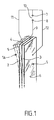
- this piezoelectric element is a piezoelectric plate bimorph.
- reference 1 designates a classic bimorph piezoelectric plate which is obtained by assembling two piezoelectric ceramic plates 2, 3 which are glued to one another, with the interposition of a thin median metal plate 4 which forms the inner electrode of bimorph 1, and which are likely to receive opposite polarizations.
- the middle electrode 4 is connected, by an electrical connecting wire 9, to a first terminal 8 of a source 10 of direct voltage, but of reversible polarity under external control, while the two external electrodes 5 and 6 are respectively connected, by respective connecting wires 11 and 12, to each other terminal 7 of this DC voltage source 10.
- the bimorph plate 1 deforms in bending in a first sense to come pick up, if it is attached to its lower end and left free to its upper end, the lateral position designated in FIG. 1 by the reference 1A.
- the free upper face of this plate will then move (to the left in the drawing) over a distance of about 0.25 to 0.5 mm depending on the quality of the electrical material and the amplitude of the DC voltage applied.
- the piezoelectric materials used here are elements remanent, which moves almost instantly (in about a millisecond to fix ideas) from position 1 to position 1A when a short pulse from command (from 1 to 3 milliseconds in width for example) is applied to them by the source 10, but which then remain, by mechanical memory effect, in this lateral deflection position lA for a relatively very long time, usually on the order of several minutes, if there is no longer any tension then applied.
- this bimorph element returns almost instantly (again in a millisecond approximately) to its initial position 1A.
- This element behaving like a capacity, the simple fact of short-circuiting, in the absence of supply 10, points 7 and 8 causes the discharge of said capacity and the result obtained is identical.
- the bimorph returns almost instantly to its initial position.
- FIG 2 it is therefore a device which is intended to collect or reject 13 coins which arrive one behind the other in an inclined chute 14 which here consists of two cheeks lateral and substantially vertical 15, 16 and a bottom plate 17 which is inclined a few tens of degrees with respect to the horizontal.
- the chute 14 has a width slightly greater than the width of the pieces 13, so that their allow driving without difficulty.
- the coins 13 can also be tokens circular, which is the same thing.
- the flap 17A is normally returned to the alignment position with the entire bottom 17, according to the position of FIG. 2, by an elastic return spring 18. It rotates around an axis 19 which is outside the chute 14 and parallel to the latter, so that, as shown, the flap 17A comes into high abutment against the two lower edges of the two cheeks 15, 16 of this chute. Axis 19 is carried by end bearings 20, 21.
- the return force of the spring 18 is low enough for the flap 17A tilts down, turning around axis 19, under the weight of a part incident 13. In this case, the part 13 falls into a discharge chute 22 and is thus evacuated to the outside. For clarity of design, the front cheek of this discharge chute 22 is not shown in FIG. 2.
- a bimorph piezoelectric plate 1 As shown, a bimorph piezoelectric plate 1 according to the Figure 1 is positioned upright, parallel to the chute 14, and very close to the edge free 23 of the tilting flap 17A, at a distance therefrom which, for example of the order of 0.1 mm, is sufficient to allow the flap 17A to swing freely when this bimorph 1 does not receive a DC bias voltage.
- the bimorph plate 1 is fixed to its lower part in holding jaws 24, 25.
- a three-pin socket 26 makes it possible to carry out the connection, according to Figure 1, of the three electrodes 4, 5, 6 of the bimorph plate 1.
- the central electronic unit (not shown) is then inactive and no bias voltage is applied to the element bimorph 1 via its connection socket 26, so that these parts 13 therefore make tilt the flap 17A to fall into the discharge chute 22 and therefore be thrown out to be returned to this clumsy user.
- a bimorph piezoelectric plate is an element physically remanent, which therefore retains its 1A deformation during time required to introduce the next part, but under unit control electronic sorting which will confirm the validity of the coin or token by issuing an impulse validating the position of the bimorph.
- a pulse of opposite polarity or a short circuit of the bimorph element the will return to the original position and the part will be evacuated.
- the element reaction time must be very fast, since the rejection decision is taken by the detection which is located a few centimeters upstream and that the part or the token rolls on the slide 17.
- the central electronic unit controls the bimorph plate 1 of so that it then remains in its deflection position 1A. This can be done either by sending no electrical impulse to socket 26, and we then consider that the bimorph remains in its deflected position 1A by pure mechanical remanence effect, or, for more security in case we are dealing with a very slow user, sending on this bimorph a polarization pulse identical to that which had was sent when the handset was lifted.
- the part 13 then rolls normally on the flap 17A to continue then its way in the trough 14, towards the cashing device placed in downstream.
- the central electronic unit sends an impulse to socket 26 brief, identical to the previous one but of opposite sign, or short-circuit of the element as described below.
- the bimorph element then returns almost instantaneously (in one approximately millisecond) to its starting position 1 where it is released from the tilting flap 17A. The latter then switches when the part 13 reaches it, and the latter is discharged to the outside via the discharge chute 22.
- the piezoelectric element used could be something other than a bimorph plate, for example example a multimorphic bar.
Landscapes
- Physics & Mathematics (AREA)
- General Physics & Mathematics (AREA)
- Control Of Vending Devices And Auxiliary Devices For Vending Devices (AREA)
Applications Claiming Priority (2)
| Application Number | Priority Date | Filing Date | Title |
|---|---|---|---|
| FR9613207 | 1996-10-24 | ||
| FR9613207A FR2755275B1 (fr) | 1996-10-24 | 1996-10-24 | Dispositif d'encaissement ou de rejet de pieces de monnaie ou de jetons circulaires, et son procede de mise en oeuvre |
Publications (1)
| Publication Number | Publication Date |
|---|---|
| EP0840261A1 true EP0840261A1 (de) | 1998-05-06 |
Family
ID=9497153
Family Applications (1)
| Application Number | Title | Priority Date | Filing Date |
|---|---|---|---|
| EP97420176A Withdrawn EP0840261A1 (de) | 1996-10-24 | 1997-10-01 | Vorrichtung zur Einnahme oder Rückgabe von runden Münzen oder Wertmarken |
Country Status (4)
| Country | Link |
|---|---|
| US (1) | US5901828A (de) |
| EP (1) | EP0840261A1 (de) |
| AU (1) | AU736755C (de) |
| FR (1) | FR2755275B1 (de) |
Cited By (1)
| Publication number | Priority date | Publication date | Assignee | Title |
|---|---|---|---|---|
| EP3407311A1 (de) * | 2017-05-24 | 2018-11-28 | Glory Ltd. | Münzenumlenker und münzenhandhabungsvorrichtungen |
Families Citing this family (8)
| Publication number | Priority date | Publication date | Assignee | Title |
|---|---|---|---|---|
| US6520308B1 (en) * | 1996-06-28 | 2003-02-18 | Coinstar, Inc. | Coin discrimination apparatus and method |
| US6052452A (en) * | 1998-07-15 | 2000-04-18 | Chuang; Tung-Wen | Pay phone |
| JP4997374B2 (ja) * | 2005-10-19 | 2012-08-08 | 旭精工株式会社 | 硬貨の金種別振り分け装置 |
| US9036890B2 (en) | 2012-06-05 | 2015-05-19 | Outerwall Inc. | Optical coin discrimination systems and methods for use with consumer-operated kiosks and the like |
| US8967361B2 (en) | 2013-02-27 | 2015-03-03 | Outerwall Inc. | Coin counting and sorting machines |
| US9022841B2 (en) | 2013-05-08 | 2015-05-05 | Outerwall Inc. | Coin counting and/or sorting machines and associated systems and methods |
| US9443367B2 (en) | 2014-01-17 | 2016-09-13 | Outerwall Inc. | Digital image coin discrimination for use with consumer-operated kiosks and the like |
| EP4571689A1 (de) * | 2023-12-13 | 2025-06-18 | Innovative Technology Limited | Münzenaufnahmeeinheit |
Citations (1)
| Publication number | Priority date | Publication date | Assignee | Title |
|---|---|---|---|---|
| EP0147112A2 (de) * | 1983-12-09 | 1985-07-03 | Nippon Telegraph And Telephone Corporation | Piezoelektrische Antriebsvorrichtung mit einem bilaminaren Element |
Family Cites Families (5)
| Publication number | Priority date | Publication date | Assignee | Title |
|---|---|---|---|---|
| US2032517A (en) * | 1935-01-31 | 1936-03-03 | Bell Telephone Labor Inc | Coin collecting device |
| FR2494011A1 (fr) * | 1980-11-07 | 1982-05-14 | Serres Bernard | Dispositif accumulateur-encaisseur de pie ces de monnaie a ejection |
| US5167314A (en) * | 1984-10-10 | 1992-12-01 | Coin Acceptors, Inc. | Coin guiding device |
| DE4235652C2 (de) * | 1992-10-22 | 1996-02-08 | Nat Rejectors Gmbh | Verstellbare Weiche für ein Münzgerät |
| DE9318856U1 (de) * | 1993-12-08 | 1994-07-28 | Wohlrab, Ekhart, Dr.-Ing., 21684 Stade | Sortiereinrichtung für Münzen |
-
1996
- 1996-10-24 FR FR9613207A patent/FR2755275B1/fr not_active Expired - Fee Related
-
1997
- 1997-09-30 AU AU39329/97A patent/AU736755C/en not_active Ceased
- 1997-10-01 EP EP97420176A patent/EP0840261A1/de not_active Withdrawn
- 1997-10-07 US US08/946,214 patent/US5901828A/en not_active Expired - Fee Related
Patent Citations (1)
| Publication number | Priority date | Publication date | Assignee | Title |
|---|---|---|---|---|
| EP0147112A2 (de) * | 1983-12-09 | 1985-07-03 | Nippon Telegraph And Telephone Corporation | Piezoelektrische Antriebsvorrichtung mit einem bilaminaren Element |
Cited By (3)
| Publication number | Priority date | Publication date | Assignee | Title |
|---|---|---|---|---|
| EP3407311A1 (de) * | 2017-05-24 | 2018-11-28 | Glory Ltd. | Münzenumlenker und münzenhandhabungsvorrichtungen |
| US10629021B2 (en) | 2017-05-24 | 2020-04-21 | Glory Ltd. | Coin diverter and coin handling apparatus |
| US11250658B2 (en) | 2017-05-24 | 2022-02-15 | Glory, Ltd. | Coin diverter |
Also Published As
| Publication number | Publication date |
|---|---|
| FR2755275A1 (fr) | 1998-04-30 |
| AU736755C (en) | 2002-03-28 |
| AU3932997A (en) | 1998-04-30 |
| US5901828A (en) | 1999-05-11 |
| AU736755B2 (en) | 2001-08-02 |
| FR2755275B1 (fr) | 1999-01-08 |
Similar Documents
| Publication | Publication Date | Title |
|---|---|---|
| EP0780858B1 (de) | Miniaturvorrichtung zur Durchführung einer vorbestimmten Funktion, insbesondere Mikro-Relais | |
| EP0840261A1 (de) | Vorrichtung zur Einnahme oder Rückgabe von runden Münzen oder Wertmarken | |
| EP0181905B1 (de) | Vorrichtung zur darstellung taktiler informationen | |
| EP0007867B1 (de) | Verbesserungen an Vorrichtungen zum Feststellen des Bruchs eines Elements einer elektrischen Schaltung | |
| EP0309311A1 (de) | Überstromschalter | |
| FR2570872A1 (fr) | Dispositif de commutation a composition variable | |
| EP0299899A1 (de) | Vorrichtung zum Verriegeln und Entriegeln von Notausgängen | |
| FR2777079A1 (fr) | Dispositif pour la detection de l'ouverture d'un compteur | |
| EP0211707A1 (de) | Elektrischer Schaltschutz für Kondensatoranlagen | |
| FR2692390A1 (fr) | Sélecteur de pièces de monnaie. | |
| FR2654556A1 (fr) | Dispositif de connexion pour un appareil utilisable avec un objet portatif, notamment une clef, a circuit integre. | |
| EP2085987A1 (de) | Steuerungsvorrichtung mit zwei verschiedenen Betätigungsarten | |
| EP0052043B1 (de) | Münzen auswerfende Münzenspeicher- und Kassiereinrichtung | |
| EP0092733A1 (de) | Münzmagazin für Zahlungssystem, mit Kassierung und Rückgabe von Münzen | |
| FR2650417A1 (fr) | Trieuse de pieces de monnaie en vrac | |
| EP0696373B1 (de) | Produktverkaufsautomat mit münzprüfer | |
| EP0693765B1 (de) | Elektromagnetischer Auslöser für einen Niederspannungsschutzschalter | |
| EP0693764A1 (de) | Elektrischer Lastschalter mit elektromagnetischem Betätiger für Hochstrom | |
| EP0105816B1 (de) | Gerät zur automatischen Erdung einer zufällig unter Spannung stehenden Struktur | |
| EP0174258B1 (de) | Kassiervorrichtung mit Hemmung für öffentliche Telefone und andere zum Empfang mehrerer Münztypen geeignete Apparate mit Vorausbezahlung | |
| BE880115A (fr) | Appareil telephonique a monnayeur | |
| FR2698028A1 (fr) | Machine à écraser des boîtes métalliques, notamment des boîtes de boisson cylindriques. | |
| FR2526519A1 (fr) | Dispositif de securite de mise en route d'un appareil electrique | |
| EP4088294B1 (de) | Geschützter schalter | |
| EP4503083A1 (de) | Elektrische schutzvorrichtung, die zur automatischen bestimmung einer ursache einer öffnung einer elektrischen schaltung konfiguriert ist, und verfahren dafür |
Legal Events
| Date | Code | Title | Description |
|---|---|---|---|
| PUAI | Public reference made under article 153(3) epc to a published international application that has entered the european phase |
Free format text: ORIGINAL CODE: 0009012 |
|
| AK | Designated contracting states |
Kind code of ref document: A1 Designated state(s): AT BE CH DE DK ES FI FR GB GR IE IT LI LU NL PT SE |
|
| 17P | Request for examination filed |
Effective date: 19981027 |
|
| AKX | Designation fees paid |
Free format text: AT BE CH DE DK ES FI FR GB GR IE IT LI LU NL PT SE |
|
| RBV | Designated contracting states (corrected) |
Designated state(s): AT BE CH DE DK ES FI FR GB GR IE IT LI LU NL PT SE |
|
| 17Q | First examination report despatched |
Effective date: 19991227 |
|
| RAP1 | Party data changed (applicant data changed or rights of an application transferred) |
Owner name: COVADIS SA |
|
| GRAH | Despatch of communication of intention to grant a patent |
Free format text: ORIGINAL CODE: EPIDOS IGRA |
|
| STAA | Information on the status of an ep patent application or granted ep patent |
Free format text: STATUS: THE APPLICATION IS DEEMED TO BE WITHDRAWN |
|
| 18D | Application deemed to be withdrawn |
Effective date: 20030115 |