EP0840418A1 - Combinaison d'un boítier à encastre et d'un appareil d'installation électrique, et boítier associé - Google Patents
Combinaison d'un boítier à encastre et d'un appareil d'installation électrique, et boítier associé Download PDFInfo
- Publication number
- EP0840418A1 EP0840418A1 EP97203342A EP97203342A EP0840418A1 EP 0840418 A1 EP0840418 A1 EP 0840418A1 EP 97203342 A EP97203342 A EP 97203342A EP 97203342 A EP97203342 A EP 97203342A EP 0840418 A1 EP0840418 A1 EP 0840418A1
- Authority
- EP
- European Patent Office
- Prior art keywords
- box
- combination according
- installation material
- installation
- connecting elements
- Prior art date
- Legal status (The legal status is an assumption and is not a legal conclusion. Google has not performed a legal analysis and makes no representation as to the accuracy of the status listed.)
- Withdrawn
Links
- 238000010616 electrical installation Methods 0.000 title claims description 9
- 238000009434 installation Methods 0.000 claims description 88
- 230000001154 acute effect Effects 0.000 claims description 5
- 230000000295 complement effect Effects 0.000 claims description 5
- 238000010276 construction Methods 0.000 abstract description 2
- 241000208199 Buxus sempervirens Species 0.000 description 2
- 241000252185 Cobitidae Species 0.000 description 1
- 230000001419 dependent effect Effects 0.000 description 1
- 238000006073 displacement reaction Methods 0.000 description 1
- 238000005553 drilling Methods 0.000 description 1
- 238000004519 manufacturing process Methods 0.000 description 1
- 238000003801 milling Methods 0.000 description 1
Images





Classifications
-
- H—ELECTRICITY
- H02—GENERATION; CONVERSION OR DISTRIBUTION OF ELECTRIC POWER
- H02G—INSTALLATION OF ELECTRIC CABLES OR LINES, OR OF COMBINED OPTICAL AND ELECTRIC CABLES OR LINES
- H02G3/00—Installations of electric cables or lines or protective tubing therefor in or on buildings, equivalent structures or vehicles
- H02G3/02—Details
- H02G3/08—Distribution boxes; Connection or junction boxes
- H02G3/18—Distribution boxes; Connection or junction boxes providing line outlets
-
- H—ELECTRICITY
- H02—GENERATION; CONVERSION OR DISTRIBUTION OF ELECTRIC POWER
- H02G—INSTALLATION OF ELECTRIC CABLES OR LINES, OR OF COMBINED OPTICAL AND ELECTRIC CABLES OR LINES
- H02G3/00—Installations of electric cables or lines or protective tubing therefor in or on buildings, equivalent structures or vehicles
- H02G3/02—Details
- H02G3/08—Distribution boxes; Connection or junction boxes
- H02G3/081—Bases, casings or covers
-
- H—ELECTRICITY
- H02—GENERATION; CONVERSION OR DISTRIBUTION OF ELECTRIC POWER
- H02G—INSTALLATION OF ELECTRIC CABLES OR LINES, OR OF COMBINED OPTICAL AND ELECTRIC CABLES OR LINES
- H02G3/00—Installations of electric cables or lines or protective tubing therefor in or on buildings, equivalent structures or vehicles
- H02G3/02—Details
- H02G3/08—Distribution boxes; Connection or junction boxes
- H02G3/14—Fastening of cover or lid to box
Definitions
- the invention relates to a combination of electrical installation material, with a frame with a number of slots; and a mounting box for electrical installation material, with a floor and one or more side walls and a number of each mounted near one of the side walls Fasteners for fastening the Installation material in the box, the Fasteners are designed so that they essentially complementary shaped connecting elements from Can connect installation material through the slots.
- Simple installation boxes i.e. boxes, in which is just an electrical component, such as one Socket or a switch, is mounted
- Simple installation boxes at which this problem has been solved by essentially tangential to an imaginary fulcrum Mounting slots in a frame of the to be assembled electrical component are attached.
- Screws for fastening the electrical component the when using the mounting slots a shift in in this case a twist of the electrical component against the can so that despite one possibly a wrongly installed box is a desired one correct installation position of the electrical component on the wall can be achieved.
- the aim of the invention is to provide the possibilities Correction of the position of the electrical component compared to the Improve the position of the installation box significantly, independently whether it's a single or multi-way box concerns, wherein the above-mentioned disadvantages are eliminated.
- the combination of installation box is according to the invention and electrical installation material characterized in that the connecting elements of the can essentially in a parallel to the floor Plane at least along a straight or curved line at an acute or right angle to the associated one Let the side wall move and that the slots in are directed at an angle to the line mentioned.
- the connecting elements of the box designed to essentially in a plane running parallel to the ground in different places at least along a straight line or curved line at an acute or right angle to the associated side wall connecting elements from Include installation material, with the slots in are directed at an angle to the line mentioned.
- 1, 2 and 3 represent part of a side wall 2 a single or multiple not shown Junction box.
- a hollow column 4 attached, the cavity one has an oval cross-section.
- the column 4 also has one Slot 6, in which one in FIGS. 4 and 5 shown nut 8 with an opening 10 which is threaded is provided, can push.
- the pushing motion of the nut 8 in slot 6 is through the guide surfaces 6a, 6b, 6c and 6d and in one direction by a cam 12 and in the opposite direction by tapering Wall parts 6e of slot 6 against which the side surfaces 8a encounter the mother 8, limited.
- the opening 10 of the nut 8 over the Move the cross section of the oval cavity in column 4.
- a connecting element to be connected to the nut 8 Installation material in the form of a screw can be thanks to the Use of the sliding nut 8 different, continuous selectable positions opposite the side wall 2 of the installation box, which is why, regardless of one possible inclination of the installation box in a hole Wall, the installation material correctly aligned to the Wall can be mounted.
- the web is the Choose mother so that it is in the installation box installation material to be installed in relation to the Can actually move the installation box or twist it.
- all tracks of the individual nuts 8 must be essentially tangential to an imaginary center of the installation box lie.
- the tracks of the Nuts 8 at an angle other than zero Longitudinal direction of the associated mounting slots run to a shift, if necessary, an angular rotation of the installation material compared to the installation box.
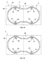
- FIG. 5a and 5b which is a schematic Representation of a double installation box 1 with a bottom 1a and show a side wall 2 in continuous lines, illustrate this.
- the box is with four sliding Provided nuts, each nut in a lineup the in 1-5 is shown in more detail.
- a frame 3 is given, which in practice two will support electrical elements. It can also do that Talk about two separate frames 3a and 3b, each provided with an electrical element.
- the frame 3 or the frames 3a and 3b are provided with slots 3c, which are essentially perpendicular to those with Continuous line indicated areas are.
- FIG. 5a shows the installation position of the installation material in the installation box if the installation box is not is installed obliquely in a wall
- Fig. 5b a Possibility to correct the location of the installation material with a built-in box installed at an angle in the wall illustrates when using screws the by Slots 3c are screwed into the openings of the nut.
- Fig. 6 represents part of a side wall 2 one Installation box, with a column 14 provided inside which extends to the bottom of the installation box.
- the Column 14 is at the number 16 Point interrupted by a predetermined distance. This distance is a little larger than the thickness of one nut 18 to be fitted therein with an opening 20 which is threaded.
- column 14 there is a Hole 22 with an oval cross section, the longitudinal direction of the Ovals runs at an acute angle to the side wall 2.
- the opening 20 can in the interruption 16 different places with hole 22 aligned be, which is why a screw connection between the Installation material and the mother 18 opposite the Side wall 2 of the mounting box is displaceable.
- Fig. 7 shows a on a larger scale alternative embodiment of the nut 18 in Fig. 6:
- Fig. 7 is a nut 18a with a threaded opening 20a in Compared to the nut 18 shortened so that the thread on a point along the circumference is interrupted.
- Under Maintaining the mother 's push options in the Interruption 16 can hereby be achieved that the Mother, regardless of the mother's mounting position, does not have the limits of the break 16 protrude.
- the Edges of the plate defining the opening 20b so shaped are that they form part of a screw thread.
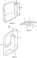
- Fig. 9 shows the side wall 2 of a mounting box in a similar design as in Fig. 1-5 represents, with on the inward-facing side with a oval hole cross section 25 provided column 24 attached is.
- a slit-shaped, tapering from outside to inside Slot 26 provided in which there is also a conical tapered plate 28 in the longitudinal direction of the oval Cross section of the hole 25 of column 24 can move.
- the Plate 28 has an elongated recess in which with 29 designated parts of a screw thread are formed with a screw for fastening Work together the installation material in the installation box can.
- Fig. 10 shows an embodiment with the 9 is comparable.
- plate 30 can be in side wall 2 and column 24 be firmly attached.
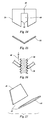
- the also in Figs. 11 and 12 Plate 30 shown is with an elongated recess provided with two parallel long sides, one have a sharp edge.
- the edges 32 are shaped so that they fit into the thread of a for attaching the installation material in the installation box grab screw 34 used. Thanks to the parallel edges 32, the screw in the oval cavity 25th move, giving a way to correct the Location of the installation material compared to the location of the Installation box is created.
- Fig. 13 shows a plate on a different scale 36, which consists of a number of stacked plates 30 10-12.
- the plate 36 creates in comparison to plate 30 an improved connection with a Screw.
- Fig. 14-16 represent an alternative embodiment of plate 30 according to FIGS. 10-12: plate 38 according to FIG. 14-16 is kinked along line 40, which is why parallel edges 42 of an elongated recess 44 in the Plate 38 just run and still fit well into one Can grip screw 34 (see Fig. 16).
- Another Advantage of the plate 38 is that it is in the art a barb pulling out the screw 34 in the direction indicated by arrow 46 (see FIG. 16) prevented.
- FIG. 17 shows a further development of the one in FIG. 14-16 contained the thought, the in Fig. 17 plates 48 shown show what from plate 38 to the removal of the adapter in the place of line 40 remains.
- the plates 48 according to FIG. 17 can be on analogous to plate 30 in Fig. 10 in one or two Slit (s) of the side wall 2 and the column 24 one Mounting box to be attached, keeping them along each other facing edges 49 on the basis of FIGS. 14-16 act explained way.
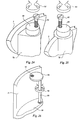
- FIGS. 18 and 19 illustrate the use of a movable arm 50 which is near an end 50a is connected to the side wall 2 of a mounting box and on other end 50b is partially threaded.
- the Fastening point of a screw 54 at the end 50b of arm 50 to be moved in two opposite directions.
- Of the Arm can be in a column 56, shown only schematically be housed.
- FIG. 20 shows a modified form of the Embodiment according to FIGS. 18 and 19.
- the Arm 50 from the bottom 58 of a mounting box into a cavity 60 pushed a column 62, the end 50c so shaped is that it closes cavity 60.
- cylindrical element 80 is eccentrically provided with a threaded hole into which one screw 82 connected to installation material can be screwed in.
- arrows 84 recognize, the position of the threaded hole in the cylindrical element 80 opposite the side wall 2 of the Installation box by turning the cylindrical element 80, providing a way to correct the position of the Installation material compared to the position of the installation box consists.
- Fig. 26 represents a modified form of the 24 and 25 illustrate the principle, one Plate 86 at one end of a twistable arm 88 is attached, the other end at the bottom 90 of a mounting box is attached.
- the plate 86 has removed from the attachment point on the arm 88 with an opening 91 Thread.
- the Rotate plate 86 around arm 88, arm 88 twisting and displacement of the opening 91 from that Side wall 2 of the installation box occurs.
- the arm 88 and the Plate 86 can be in the cavity of one, not shown Column.
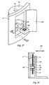
- FIG. 27 shows a part of the side wall 2 of one Installation box, with a hollow column inside the box 94 is located on the from the bottom of the junction box opposite end with an opening 96 with an oval Cross section is provided.
- a hollow column inside the box 94 is located on the from the bottom of the junction box opposite end with an opening 96 with an oval Cross section is provided.
- a flap 102 provided in the side wall 2 can close the cavity in column 94 and the nut Include 100 between stops 98.
- a screw 104 in can be seen through the opening 96 the nut 100 are screwed, the nut 100 between the stops 98 as a hinge point for the screw 104 acts. This can be done from the bottom of the box opposite end of the screw 104 in the directions of the Shift double arrow 106, which is another possibility to correct the position of the screw 104 Installation material compared to the position of the installation box is created.
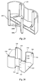
- Fig. 29 shows a double installation box with a double bottom 108a, 108b.
- the installation box has two U-shaped combined fasteners 110 attached the place where they are in the double bottom 108a, 108b cross, are articulated together.
- a Hinge connection is otherwise not essential.
- the Connecting elements 110 can also be separate from one another or even be arranged parallel to each other.
- the upward leg of the connecting elements 110 have openings at the free ends, for example can be threaded.
- the fasteners 110 can move in grooves of the bottom part 108b.
- Fig. 30 shows a connecting element which for the Use in a double mounting box is intended and made there is a set of base plates 112, one at each Set of side plates 114 with columns 116 is attached.
- the Base plates 112 are interconnected via a bridge 118 connected to the bottom of a double junction box can be articulated, the shape of the Side wall with that of the installation box according to FIG. 29 matches.
- the pillars 116 have holes 120 for Fasteners from the installation material.
- Fig. 31 shows a combined, substantially X-shaped Quadruple connector 122, the central part 124 articulated with a double mounting box in the middle assembled column 126 can be connected.
- the Connector 122 has at the ends of the four Leg holes 128, which may be threaded could be.
- one end of a Leg of the connecting element 122 in a slot be introduced inside the double junction box by an interruption in a wall-mounted Pillar is formed.
- the end of the hole 128 Connector 122 may be in the break in move the directions of the double arrow 130. That remains sufficient in the column on both sides of opening 128 Space so that one is located in opening 128 Can move screw over a predetermined distance.
Landscapes
- Engineering & Computer Science (AREA)
- Architecture (AREA)
- Civil Engineering (AREA)
- Structural Engineering (AREA)
- Casings For Electric Apparatus (AREA)
Applications Claiming Priority (2)
| Application Number | Priority Date | Filing Date | Title |
|---|---|---|---|
| NL1004392A NL1004392C2 (nl) | 1996-10-30 | 1996-10-30 | Inbouwdoos voor electrisch installatiemateriaal. |
| NL1004392 | 1996-10-30 |
Publications (1)
| Publication Number | Publication Date |
|---|---|
| EP0840418A1 true EP0840418A1 (fr) | 1998-05-06 |
Family
ID=19763767
Family Applications (1)
| Application Number | Title | Priority Date | Filing Date |
|---|---|---|---|
| EP97203342A Withdrawn EP0840418A1 (fr) | 1996-10-30 | 1997-10-29 | Combinaison d'un boítier à encastre et d'un appareil d'installation électrique, et boítier associé |
Country Status (2)
| Country | Link |
|---|---|
| EP (1) | EP0840418A1 (fr) |
| NL (1) | NL1004392C2 (fr) |
Cited By (2)
| Publication number | Priority date | Publication date | Assignee | Title |
|---|---|---|---|---|
| EP1343238A1 (fr) * | 2002-03-07 | 2003-09-10 | Legrand | Boîtier pour appareillage électrique à fixation souple |
| EP3217767A1 (fr) * | 2016-03-11 | 2017-09-13 | Hiasset GmbH | Système de maison intelligente |
Families Citing this family (1)
| Publication number | Priority date | Publication date | Assignee | Title |
|---|---|---|---|---|
| WO2013144970A1 (fr) * | 2012-03-30 | 2013-10-03 | Ganatra Prashant Haridas | Boîtier électrique monté à fleur |
Citations (2)
| Publication number | Priority date | Publication date | Assignee | Title |
|---|---|---|---|---|
| DE1922588U (de) * | 1965-07-02 | 1965-09-02 | Chem Fab Dr Franz & Rutenbeck | Unterputz-installationsapparat. |
| DE3507897C1 (de) * | 1985-03-06 | 1986-04-17 | Albert Ackermann GmbH & Co KG, 5270 Gummersbach | Geräteeinbaudose für Kabelkanäle |
-
1996
- 1996-10-30 NL NL1004392A patent/NL1004392C2/nl not_active IP Right Cessation
-
1997
- 1997-10-29 EP EP97203342A patent/EP0840418A1/fr not_active Withdrawn
Patent Citations (2)
| Publication number | Priority date | Publication date | Assignee | Title |
|---|---|---|---|---|
| DE1922588U (de) * | 1965-07-02 | 1965-09-02 | Chem Fab Dr Franz & Rutenbeck | Unterputz-installationsapparat. |
| DE3507897C1 (de) * | 1985-03-06 | 1986-04-17 | Albert Ackermann GmbH & Co KG, 5270 Gummersbach | Geräteeinbaudose für Kabelkanäle |
Cited By (4)
| Publication number | Priority date | Publication date | Assignee | Title |
|---|---|---|---|---|
| EP1343238A1 (fr) * | 2002-03-07 | 2003-09-10 | Legrand | Boîtier pour appareillage électrique à fixation souple |
| FR2837030A1 (fr) * | 2002-03-07 | 2003-09-12 | Legrand Sa | Boitier pour appareillage electrique a fixation souple |
| US6976601B2 (en) | 2002-03-07 | 2005-12-20 | Legrand | Electrical equipment box with flexible fixing arrangements |
| EP3217767A1 (fr) * | 2016-03-11 | 2017-09-13 | Hiasset GmbH | Système de maison intelligente |
Also Published As
| Publication number | Publication date |
|---|---|
| NL1004392C2 (nl) | 1997-10-07 |
| NL1004392A1 (nl) | 1997-06-19 |
Similar Documents
| Publication | Publication Date | Title |
|---|---|---|
| DE102013112645B3 (de) | Türband | |
| DE102006060586B4 (de) | Ausrichtbares Scharnier | |
| DE29811479U1 (de) | Plattenanordnung zur Osteosynthese | |
| DE2514357B2 (de) | Beschlag zum verschwenkbaren Verbinden einer Möbelplatte mit einem feststehenden Möbelteil | |
| EP0422678B1 (fr) | Coffre à bagages | |
| DE10102422B4 (de) | Mutteranordnung mit schwenkbarer Mutter | |
| DE3348215C2 (fr) | ||
| EP0413768B1 (fr) | Dispositif de montage de fixations de ski | |
| DE3617581C2 (fr) | ||
| EP1999830B1 (fr) | Module de montage destine a installer un appareil dans une installation de commutation electrique | |
| DE8914027U1 (de) | Steckerträger zum Anbau an ein Aggregategehäuse | |
| EP1394347B1 (fr) | Dispositif de guidage pour partitions coulissantes et élément de guidage élastique | |
| DE3141158C2 (de) | Führungsvorrichtung für einen ein- und ausfahrbaren Einsatz im Korpus eines Schrankes | |
| EP3963219B1 (fr) | Dispositif d'assemblage et meuble | |
| DE102005000020B4 (de) | Anordnung zur Halterung eines Installationsgeräte-Einsatzes an einer Tragplatte | |
| AT411094B (de) | Steckverbindung | |
| EP0931885A2 (fr) | Caniveau d'écoulement | |
| EP0959536B1 (fr) | Bloc multiprises | |
| EP0423474B1 (fr) | Dispositif pour relier deux baguettes profilées de façon à ce qu'elles soient détachables | |
| DE2601809B2 (de) | Scharnier, insbesondere für Möbel | |
| DE19644372B4 (de) | Versatzausgleich für eine Installationsgerätekombination | |
| EP1039154B1 (fr) | Système de fixation | |
| EP1859752A1 (fr) | Plaque d'ostéosynthèse | |
| DE10050279A1 (de) | Flexfolienverlegehilfe | |
| DE19815602A1 (de) | Befestigungssystem zum Befestigen einer Platte innerhalb eines Gehäuses |
Legal Events
| Date | Code | Title | Description |
|---|---|---|---|
| PUAI | Public reference made under article 153(3) epc to a published international application that has entered the european phase |
Free format text: ORIGINAL CODE: 0009012 |
|
| AK | Designated contracting states |
Kind code of ref document: A1 Designated state(s): BE DE DK FR LU NL |
|
| AX | Request for extension of the european patent |
Free format text: AL;LT;LV;RO;SI |
|
| 17P | Request for examination filed |
Effective date: 19981028 |
|
| AKX | Designation fees paid |
Free format text: BE DE DK FR LU NL |
|
| RBV | Designated contracting states (corrected) |
Designated state(s): BE DE DK FR LU NL |
|
| 17Q | First examination report despatched |
Effective date: 20020409 |
|
| STAA | Information on the status of an ep patent application or granted ep patent |
Free format text: STATUS: THE APPLICATION IS DEEMED TO BE WITHDRAWN |
|
| 18D | Application deemed to be withdrawn |
Effective date: 20040302 |