EP0931885A2 - Caniveau d'écoulement - Google Patents
Caniveau d'écoulement Download PDFInfo
- Publication number
- EP0931885A2 EP0931885A2 EP99810035A EP99810035A EP0931885A2 EP 0931885 A2 EP0931885 A2 EP 0931885A2 EP 99810035 A EP99810035 A EP 99810035A EP 99810035 A EP99810035 A EP 99810035A EP 0931885 A2 EP0931885 A2 EP 0931885A2
- Authority
- EP
- European Patent Office
- Prior art keywords
- bracket
- channel
- cover
- locking
- recess
- Prior art date
- Legal status (The legal status is an assumption and is not a legal conclusion. Google has not performed a legal analysis and makes no representation as to the accuracy of the status listed.)
- Granted
Links
- 239000004033 plastic Substances 0.000 claims description 5
- 230000014759 maintenance of location Effects 0.000 description 5
- JEIPFZHSYJVQDO-UHFFFAOYSA-N iron(III) oxide Inorganic materials O=[Fe]O[Fe]=O JEIPFZHSYJVQDO-UHFFFAOYSA-N 0.000 description 2
- 229910001018 Cast iron Inorganic materials 0.000 description 1
- 229920004943 Delrin® Polymers 0.000 description 1
- 238000005452 bending Methods 0.000 description 1
- 238000002347 injection Methods 0.000 description 1
- 239000007924 injection Substances 0.000 description 1
- 239000002184 metal Substances 0.000 description 1
- 229910052751 metal Inorganic materials 0.000 description 1
- 238000004080 punching Methods 0.000 description 1
- 229920001169 thermoplastic Polymers 0.000 description 1
- 239000004416 thermosoftening plastic Substances 0.000 description 1
Images


Classifications
-
- E—FIXED CONSTRUCTIONS
- E03—WATER SUPPLY; SEWERAGE
- E03F—SEWERS; CESSPOOLS
- E03F5/00—Sewerage structures
- E03F5/04—Gullies inlets, road sinks, floor drains with or without odour seals or sediment traps
- E03F5/06—Gully gratings
-
- E—FIXED CONSTRUCTIONS
- E03—WATER SUPPLY; SEWERAGE
- E03F—SEWERS; CESSPOOLS
- E03F5/00—Sewerage structures
- E03F5/04—Gullies inlets, road sinks, floor drains with or without odour seals or sediment traps
- E03F5/06—Gully gratings
- E03F2005/063—Gully gratings with slidable or rotatable locking elements
-
- E—FIXED CONSTRUCTIONS
- E03—WATER SUPPLY; SEWERAGE
- E03F—SEWERS; CESSPOOLS
- E03F5/00—Sewerage structures
- E03F5/04—Gullies inlets, road sinks, floor drains with or without odour seals or sediment traps
- E03F5/06—Gully gratings
- E03F2005/065—Gully gratings with elastic locking elements
Definitions
- a drainage channel with a safety device, with which grate is attached to the channel body is off known from EP-A-81 741. It includes a bracket over a Screw is connected to the grate. The rust is on the The upper edge of the channel body is placed, with the bracket essentially is aligned in the longitudinal direction of the cover. Subsequently the screw is turned so that the bracket is in opposite Recesses in the side walls of the channel body swings in until it stops. By further turning the screw, the grate is braced against the bracket and the bracket lays against the top of the recesses.
- This known securing device is only used as a screw locking device can be used with a single screw, since only in this Way the pivoting movement of the bracket can be generated.
- This fastening device has the disadvantage that the Bracket itself has the clamping device, which is in the channel fits non-positively and also supports the individual elements that enable the screwlessness of the attachment. There the assembly of the cover requires several individual elements the advantage of screwless fastening is relativized.
- the invention lies Task based on a drainage channel with a safety device to improve the type mentioned at the beginning, that the screwless mounting of the cover is easy becomes feasible.
- This task is characterized by the Features of claim 1 solved.
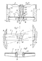
- the drainage channel according to FIG. 1 comprises a channel body 1 with two side walls 2 and a bottom 3. On opposite sides Places the side walls 2 each have pairs of Recesses 4. Locking brackets 5 are inserted into these have a continuous opening 6 in the middle. In this opening 6 is a snap-in element 7 which can be snapped in, which has a cover 9, e.g. a rust, is captively connected, e.g. with the help of Screws 8.
- the screws 8 are preferably only one Special tool can be assembled and disassembled, so when removing the cover 9 is not accidentally loosened the screws 8 first become.
- Figure 4 shows the recesses 4 of the channel in a side view.
- the recesses 4 are cast in a side wall 2 Insert 14 made of plastic or metal.
- the bracket 5 is pivoted in the direction of Arrow 15 inserted into the recesses 4.
- the recess 4 has a cross section tapering in the direction of the stop surface 16 and a retention recess 17 at the end near the stop their lower ramp surface 18.
- the bracket 5 is in the two opposite recesses 4 in their rear areas 19 in a diagonal to the longitudinal direction of the channel 1 Inserted and then in the direction of arrow 15 pivoted up to the retention recess 17.
- the bracket 5 is in Cross section U-shaped.
- a retention cam 21 in the area of the retention recess 17 diagonally opposite side of the bracket 5 can be provided, the powerless extension of the bracket 5 prevented.
- Figures 2 and 3 show a cross section through a channel according to Figure 1 or a longitudinal section.
- analogues Provide parts with the same reference numerals.
- support surfaces 26 are provided, on which the cover 9 is placed.
- the axis of symmetry 27 the opening 6 is vertical.
- the opening 6 is by punching and Bending shaped, initially two parallel, one side Rectangular lines 28 and a transverse center line punched out and the flaps 30 formed thereby double be folded. This makes two opposing, wedge surfaces 31 tapering downwards and two opposite, subsequent, widening downwards Wedge surfaces 32 formed.
- the latching element 7 has two spreading wings 37, which follow engaging surfaces 38 inclined below against the axis 27 via the Wedge surfaces 31 slide, the spreading wings 37 against each other be pressed. After passing through the narrowest part of the Opening 6, wings 37 spread again until finally when cover 9 is fully inserted with its upper, wedge-shaped surfaces 39 form-fitting but essentially without Apply bias to the wedge surfaces 32.
- the head 49 of the locking element 7 is preferably one Injected nut 50, which cooperates with the screw 8.
- the complete one can also be used Internal thread in the head 49 and / or in the shaft 47 of the latching element 7 be injection molded.
- a press pin connection to the cover 9 can be established become.
- Figure 5 shows the bracket 5 according to a second embodiment, in which the opening 6 is formed in an insert 43 is.
- This is preferably made of plastic and is in one Through opening 44 snapped.
- the surfaces 31, 32 are in this embodiment frustoconical surfaces.
- the bracket 5 can also be made entirely of plastic. In this case the insert 43 can be integrally formed on the bracket 5.
- FIGS. 6 and 7 show a latching element 7 with four wings 37.
- the wings 37 are separated from one another by transverse slots 53.
- the surfaces 38, 39 are conical, so that this element is suitable for the embodiment of the bracket 5 according to Figure 5 is suitable.
- the areas 31, 32 and 38, 39 of the embodiment according to FIGS. 5 to 7 can alternatively also be formed in the shape of a truncated pyramid.
- This latching element 7 has a central blind hole 54 for receiving the shaft of the screw 8. There can also be three or more be provided as four wings 37.
- the bracket 5 cast iron. Such brackets 5 are available more cheaply, the lower the demands placed on the tolerances.
- the insert 14 on the underside of the Recess 4 an elastic web 58 through a Slot 59 is separated from the rear wall 60 of the recess 4.
- a retention cam 61 trained.
- the wedge surfaces facing area 19 62 of the cams 21, 61 are much flatter than the others Wedge surfaces 63 so that the mounting of the bracket easier and an unintentional swinging out of the bracket 5 from the assembled Situation is difficult.
- the insert 14 has the recess 4 opposite side one more open to the outside Recess 64. This facilitates the assembly of the insert 14 in the mold for the channel body 1.
- the web 58 springs down until the cams 21, 61 behind engage the swiveled bracket 5.
- the resilient wings 37 of the locking element 7 below by a conical, on the Tip rounded connector 68 connected together.
- This has the advantage that none of the wings 37 are more imprecise Centering of the grate 9 on the channel body 1 can break off.
- the wings 37 are separated from one another by continuous transverse slots 69 Cut.
- the transverse slots 69 have a rectangular cross section and are rounded at the top and bottom.
- the nut thread for receiving the screw 8 is directly in the shaft 47 of the locking element 7 cast in, which consists of a high impact Thermoplastics, e.g. from Delrin.
- FIGS. 11 and 12 show variants of the insert 14 according to FIG 10, the resilient web 58 extending only over part of the Length of the recess 4 extends.
- the resilient web 58 In the assembled position of the bracket 5 lies its underside on a non-resilient web 73 on. This has the main advantage that when the bracket is inserted this does not go down when the latching element 7 is pressed in deflected and the opening 6 is not tilted.
- the resilient web 58 is integral with the insert 14 molded, in the variant of Figure 12 in a groove 74 of Insert 14 inserted.
- FIGS. 13 to 16 show a further embodiment in which the resilient link to snap the bracket 5 behind the Cam 61 on a sleeve attached to the ends of the bracket 5 78 is formed, which has a spring leg 79 at the bottom, which engages behind the cam 61.
Landscapes
- Health & Medical Sciences (AREA)
- Life Sciences & Earth Sciences (AREA)
- Engineering & Computer Science (AREA)
- Hydrology & Water Resources (AREA)
- Public Health (AREA)
- Water Supply & Treatment (AREA)
- Connection Of Plates (AREA)
- Mutual Connection Of Rods And Tubes (AREA)
- Sink And Installation For Waste Water (AREA)
- External Artificial Organs (AREA)
- Liquid Developers In Electrophotography (AREA)
- Sewage (AREA)
Applications Claiming Priority (2)
| Application Number | Priority Date | Filing Date | Title |
|---|---|---|---|
| CH14698 | 1998-01-22 | ||
| CH14698 | 1998-01-22 |
Publications (3)
| Publication Number | Publication Date |
|---|---|
| EP0931885A2 true EP0931885A2 (fr) | 1999-07-28 |
| EP0931885A3 EP0931885A3 (fr) | 1999-10-27 |
| EP0931885B1 EP0931885B1 (fr) | 2005-12-14 |
Family
ID=4180304
Family Applications (1)
| Application Number | Title | Priority Date | Filing Date |
|---|---|---|---|
| EP99810035A Expired - Lifetime EP0931885B1 (fr) | 1998-01-22 | 1999-01-19 | Caniveau d'écoulement |
Country Status (4)
| Country | Link |
|---|---|
| EP (1) | EP0931885B1 (fr) |
| AT (1) | ATE312981T1 (fr) |
| DE (1) | DE59912906D1 (fr) |
| ES (1) | ES2255239T3 (fr) |
Cited By (7)
| Publication number | Priority date | Publication date | Assignee | Title |
|---|---|---|---|---|
| EP1138832A3 (fr) * | 2000-03-31 | 2003-01-22 | ACO Severin Ahlmann GmbH & Co. KG | Dispositif de sécurité pour rigole d'évacuation des eaux |
| EP1559840A3 (fr) * | 2004-01-27 | 2005-11-16 | Poly Bauelemente AG | Caniveau d'écoulement |
| EP1632605A1 (fr) | 2004-09-01 | 2006-03-08 | Poly-Bauelemente AG | Caniveau d'écoulement, corps de canal et leur assemblage |
| DE102006031847A1 (de) * | 2006-07-10 | 2008-01-24 | Aco Severin Ahlmann Gmbh & Co. Kg | Befestigungseinrichtung zur Befestigung einer Abdeckung |
| DE102006053345A1 (de) * | 2006-11-10 | 2008-05-15 | Mea Bausysteme Gmbh | Rinne |
| KR101088761B1 (ko) | 2011-03-16 | 2011-12-01 | 김경호 | 맨홀 |
| EP2789755A1 (fr) * | 2013-04-12 | 2014-10-15 | MEA Bausysteme GmbH | Fixation d'une grille sur un caniveau |
Citations (2)
| Publication number | Priority date | Publication date | Assignee | Title |
|---|---|---|---|---|
| EP0081741A1 (fr) | 1981-12-12 | 1983-06-22 | ACO Severin Ahlmann GmbH & Co. KG | Caniveau d'écoulement avec dispositif de recouvrement |
| EP0604446A1 (fr) | 1991-07-22 | 1994-07-06 | Processing Technologies International Limited | Procede d'extraction |
Family Cites Families (4)
| Publication number | Priority date | Publication date | Assignee | Title |
|---|---|---|---|---|
| DE4241707C2 (de) * | 1992-12-10 | 1996-11-28 | Ahlmann Aco Severin | Sicherungseinrichtung für eine Entwässerungsrinne |
| EP0761885A1 (fr) * | 1995-09-08 | 1997-03-12 | Poly-Bauelemente AG | Dispositif de verrouillage d'une grille de recouvrement sur un caniveau d'écoulement |
| DE19541653C1 (de) * | 1995-11-08 | 1996-11-14 | Ahlmann Aco Severin | Verriegelungsbolzen |
| DE19545131C2 (de) * | 1995-12-01 | 1998-07-02 | Birco Baustoffwerk Gmbh | Abdeckrostbefestigung einer Rinne |
-
1999
- 1999-01-19 AT AT99810035T patent/ATE312981T1/de not_active IP Right Cessation
- 1999-01-19 ES ES99810035T patent/ES2255239T3/es not_active Expired - Lifetime
- 1999-01-19 DE DE59912906T patent/DE59912906D1/de not_active Expired - Fee Related
- 1999-01-19 EP EP99810035A patent/EP0931885B1/fr not_active Expired - Lifetime
Patent Citations (2)
| Publication number | Priority date | Publication date | Assignee | Title |
|---|---|---|---|---|
| EP0081741A1 (fr) | 1981-12-12 | 1983-06-22 | ACO Severin Ahlmann GmbH & Co. KG | Caniveau d'écoulement avec dispositif de recouvrement |
| EP0604446A1 (fr) | 1991-07-22 | 1994-07-06 | Processing Technologies International Limited | Procede d'extraction |
Cited By (8)
| Publication number | Priority date | Publication date | Assignee | Title |
|---|---|---|---|---|
| EP1138832A3 (fr) * | 2000-03-31 | 2003-01-22 | ACO Severin Ahlmann GmbH & Co. KG | Dispositif de sécurité pour rigole d'évacuation des eaux |
| EP1559840A3 (fr) * | 2004-01-27 | 2005-11-16 | Poly Bauelemente AG | Caniveau d'écoulement |
| EP1632605A1 (fr) | 2004-09-01 | 2006-03-08 | Poly-Bauelemente AG | Caniveau d'écoulement, corps de canal et leur assemblage |
| DE102006031847A1 (de) * | 2006-07-10 | 2008-01-24 | Aco Severin Ahlmann Gmbh & Co. Kg | Befestigungseinrichtung zur Befestigung einer Abdeckung |
| DE102006031847B4 (de) | 2006-07-10 | 2019-12-12 | Aco Severin Ahlmann Gmbh & Co. Kg | Befestigungseinrichtung zur Befestigung einer Abdeckung |
| DE102006053345A1 (de) * | 2006-11-10 | 2008-05-15 | Mea Bausysteme Gmbh | Rinne |
| KR101088761B1 (ko) | 2011-03-16 | 2011-12-01 | 김경호 | 맨홀 |
| EP2789755A1 (fr) * | 2013-04-12 | 2014-10-15 | MEA Bausysteme GmbH | Fixation d'une grille sur un caniveau |
Also Published As
| Publication number | Publication date |
|---|---|
| DE59912906D1 (de) | 2006-01-19 |
| ATE312981T1 (de) | 2005-12-15 |
| EP0931885A3 (fr) | 1999-10-27 |
| EP0931885B1 (fr) | 2005-12-14 |
| ES2255239T3 (es) | 2006-06-16 |
Similar Documents
| Publication | Publication Date | Title |
|---|---|---|
| DE102013112645B3 (de) | Türband | |
| EP1546567B1 (fr) | Element de fixation | |
| DE602004001734T2 (de) | Ein Befestigungselement zur Verbindung von an einem Trägerteil | |
| EP1062123B1 (fr) | Dispositif permettant de fixer un premier element a un deuxieme element fixe | |
| DE19941499A1 (de) | Verbindungsstück zum Verbinden eines Wischblatts mit einem Wischerarm | |
| EP2312236A2 (fr) | Dispositif de liaison pour une construction de support | |
| WO2014206526A1 (fr) | Dispositif de fixation, système de fixation et procede de montage d'un dispositif de fixation sur un rail de montage | |
| EP1177387A1 (fr) | Element d'assemblage | |
| DE19912474C2 (de) | Befestigungsanordnung für die Anbringung eines Bauteils an einer C-förmigen Halteschiene | |
| DE2721625C2 (fr) | ||
| EP0931885B1 (fr) | Caniveau d'écoulement | |
| EP3586012A1 (fr) | Dispositif de fixation et module de fixation | |
| DE3038341A1 (de) | In eine wandoeffnung eines ersten bauteils einsetzbares und ueber eine rastnut mit diesem verrastbares aufnahmeteil | |
| EP1234985B1 (fr) | Système de liaison par serrage | |
| DE202013005582U1 (de) | System umfassend ein Trägerbauteil | |
| DE102017125877B4 (de) | Verankerungsbeschlag zur Verankerung in einem Werkstück | |
| DE102019206750B4 (de) | Vorrichtung zum Ausgleichen von Toleranzen zwischen einem ersten Bauteil und einem zweiten Bauteil | |
| DE2735825C2 (fr) | ||
| AT501658B1 (de) | Vorrichtung zum befestigen eines fensterrahmens mittels einer justierschraube | |
| EP1134170B1 (fr) | Structure à assemblage modulaire pour des rayons de stockage | |
| EP1022502A1 (fr) | Ecrou d'assemblage rapide et collier de serrage pour tuyaux avec un tel écrou | |
| EP0899504A2 (fr) | Boítier de luminaire | |
| DE2837373C2 (de) | Möbelbeschlagteil, insbesondere Montageplatte für einen Möbelscharnierarm | |
| DE1784261A1 (de) | Verstellplatte fuer Moebelscharniere unter Verwendung von duebelartigen Spreizbefestigungsbuchsen | |
| DE3941097C1 (en) | Cable channel or tray support - has coupling element fixable from above in form of shaft fitting selectable slots and with projection to act like hook |
Legal Events
| Date | Code | Title | Description |
|---|---|---|---|
| PUAI | Public reference made under article 153(3) epc to a published international application that has entered the european phase |
Free format text: ORIGINAL CODE: 0009012 |
|
| AK | Designated contracting states |
Kind code of ref document: A2 Designated state(s): AT BE CH DE DK ES FI FR GB IE IT LI NL |
|
| AX | Request for extension of the european patent |
Free format text: AL;LT;LV;MK;RO;SI |
|
| PUAL | Search report despatched |
Free format text: ORIGINAL CODE: 0009013 |
|
| AK | Designated contracting states |
Kind code of ref document: A3 Designated state(s): AT BE CH CY DE DK ES FI FR GB GR IE IT LI LU MC NL PT SE |
|
| AX | Request for extension of the european patent |
Free format text: AL;LT;LV;MK;RO;SI |
|
| 17P | Request for examination filed |
Effective date: 20000404 |
|
| AKX | Designation fees paid |
Free format text: AT BE CH DE DK ES FI FR GB IE IT LI NL |
|
| RAP1 | Party data changed (applicant data changed or rights of an application transferred) |
Owner name: WAVIN B.V. Owner name: POLY-BAUELEMENTE AG |
|
| RAP1 | Party data changed (applicant data changed or rights of an application transferred) |
Owner name: WAVIN B.V. Owner name: POLY-BAUELEMENTE AG |
|
| 17Q | First examination report despatched |
Effective date: 20030717 |
|
| GRAP | Despatch of communication of intention to grant a patent |
Free format text: ORIGINAL CODE: EPIDOSNIGR1 |
|
| GRAS | Grant fee paid |
Free format text: ORIGINAL CODE: EPIDOSNIGR3 |
|
| GRAA | (expected) grant |
Free format text: ORIGINAL CODE: 0009210 |
|
| AK | Designated contracting states |
Kind code of ref document: B1 Designated state(s): AT BE CH DE DK ES FI FR GB IE IT LI NL |
|
| PG25 | Lapsed in a contracting state [announced via postgrant information from national office to epo] |
Ref country code: FI Free format text: LAPSE BECAUSE OF FAILURE TO SUBMIT A TRANSLATION OF THE DESCRIPTION OR TO PAY THE FEE WITHIN THE PRESCRIBED TIME-LIMIT Effective date: 20051214 |
|
| RAP1 | Party data changed (applicant data changed or rights of an application transferred) |
Owner name: WAVIN B.V. Owner name: POLY-BAUELEMENTE AG |
|
| REG | Reference to a national code |
Ref country code: GB Ref legal event code: FG4D Free format text: NOT ENGLISH |
|
| REG | Reference to a national code |
Ref country code: CH Ref legal event code: EP |
|
| REG | Reference to a national code |
Ref country code: IE Ref legal event code: FG4D Free format text: LANGUAGE OF EP DOCUMENT: GERMAN |
|
| REF | Corresponds to: |
Ref document number: 59912906 Country of ref document: DE Date of ref document: 20060119 Kind code of ref document: P |
|
| REG | Reference to a national code |
Ref country code: CH Ref legal event code: NV Representative=s name: ISLER & PEDRAZZINI AG |
|
| GBT | Gb: translation of ep patent filed (gb section 77(6)(a)/1977) |
Effective date: 20060213 |
|
| PG25 | Lapsed in a contracting state [announced via postgrant information from national office to epo] |
Ref country code: DK Free format text: LAPSE BECAUSE OF FAILURE TO SUBMIT A TRANSLATION OF THE DESCRIPTION OR TO PAY THE FEE WITHIN THE PRESCRIBED TIME-LIMIT Effective date: 20060314 |
|
| REG | Reference to a national code |
Ref country code: ES Ref legal event code: FG2A Ref document number: 2255239 Country of ref document: ES Kind code of ref document: T3 |
|
| ET | Fr: translation filed | ||
| PLBE | No opposition filed within time limit |
Free format text: ORIGINAL CODE: 0009261 |
|
| STAA | Information on the status of an ep patent application or granted ep patent |
Free format text: STATUS: NO OPPOSITION FILED WITHIN TIME LIMIT |
|
| 26N | No opposition filed |
Effective date: 20060915 |
|
| REG | Reference to a national code |
Ref country code: CH Ref legal event code: PCAR Free format text: ISLER & PEDRAZZINI AG;POSTFACH 1772;8027 ZUERICH (CH) |
|
| REG | Reference to a national code |
Ref country code: CH Ref legal event code: PUE Owner name: ACO PASSAVANT AG Free format text: POLY-BAUELEMENTE AG#LORRAINEWEG 10#3315 BAETTERKINDEN (CH) -TRANSFER TO- ACO PASSAVANT AG#INSEL#8754 NETSTAL (CH) Ref country code: CH Ref legal event code: NV Representative=s name: MEYER & KOLLEGEN |
|
| PGFP | Annual fee paid to national office [announced via postgrant information from national office to epo] |
Ref country code: CH Payment date: 20071213 Year of fee payment: 10 |
|
| PGFP | Annual fee paid to national office [announced via postgrant information from national office to epo] |
Ref country code: ES Payment date: 20080125 Year of fee payment: 10 |
|
| PGFP | Annual fee paid to national office [announced via postgrant information from national office to epo] |
Ref country code: NL Payment date: 20080124 Year of fee payment: 10 Ref country code: IT Payment date: 20080126 Year of fee payment: 10 Ref country code: IE Payment date: 20080314 Year of fee payment: 10 Ref country code: GB Payment date: 20080320 Year of fee payment: 10 |
|
| PGFP | Annual fee paid to national office [announced via postgrant information from national office to epo] |
Ref country code: AT Payment date: 20080123 Year of fee payment: 10 |
|
| PGFP | Annual fee paid to national office [announced via postgrant information from national office to epo] |
Ref country code: FR Payment date: 20080118 Year of fee payment: 10 Ref country code: DE Payment date: 20080327 Year of fee payment: 10 |
|
| PGFP | Annual fee paid to national office [announced via postgrant information from national office to epo] |
Ref country code: BE Payment date: 20080123 Year of fee payment: 10 |
|
| REG | Reference to a national code |
Ref country code: CH Ref legal event code: PL |
|
| GBPC | Gb: european patent ceased through non-payment of renewal fee |
Effective date: 20090119 |
|
| NLV4 | Nl: lapsed or anulled due to non-payment of the annual fee |
Effective date: 20090801 |
|
| PG25 | Lapsed in a contracting state [announced via postgrant information from national office to epo] |
Ref country code: LI Free format text: LAPSE BECAUSE OF NON-PAYMENT OF DUE FEES Effective date: 20090131 Ref country code: DE Free format text: LAPSE BECAUSE OF NON-PAYMENT OF DUE FEES Effective date: 20090801 Ref country code: CH Free format text: LAPSE BECAUSE OF NON-PAYMENT OF DUE FEES Effective date: 20090131 Ref country code: AT Free format text: LAPSE BECAUSE OF NON-PAYMENT OF DUE FEES Effective date: 20090119 |
|
| REG | Reference to a national code |
Ref country code: FR Ref legal event code: ST Effective date: 20091030 |
|
| PG25 | Lapsed in a contracting state [announced via postgrant information from national office to epo] |
Ref country code: NL Free format text: LAPSE BECAUSE OF NON-PAYMENT OF DUE FEES Effective date: 20090801 Ref country code: GB Free format text: LAPSE BECAUSE OF NON-PAYMENT OF DUE FEES Effective date: 20090119 |
|
| PG25 | Lapsed in a contracting state [announced via postgrant information from national office to epo] |
Ref country code: IE Free format text: LAPSE BECAUSE OF NON-PAYMENT OF DUE FEES Effective date: 20090119 |
|
| PG25 | Lapsed in a contracting state [announced via postgrant information from national office to epo] |
Ref country code: BE Free format text: LAPSE BECAUSE OF NON-PAYMENT OF DUE FEES Effective date: 20090131 |
|
| REG | Reference to a national code |
Ref country code: ES Ref legal event code: FD2A Effective date: 20090120 |
|
| PG25 | Lapsed in a contracting state [announced via postgrant information from national office to epo] |
Ref country code: FR Free format text: LAPSE BECAUSE OF NON-PAYMENT OF DUE FEES Effective date: 20090202 Ref country code: ES Free format text: LAPSE BECAUSE OF NON-PAYMENT OF DUE FEES Effective date: 20090120 |
|
| PG25 | Lapsed in a contracting state [announced via postgrant information from national office to epo] |
Ref country code: IT Free format text: LAPSE BECAUSE OF NON-PAYMENT OF DUE FEES Effective date: 20090119 |