EP0841033A2 - Tuyau d'aspiration téléscopique pour aspirateur - Google Patents
Tuyau d'aspiration téléscopique pour aspirateur Download PDFInfo
- Publication number
- EP0841033A2 EP0841033A2 EP97115878A EP97115878A EP0841033A2 EP 0841033 A2 EP0841033 A2 EP 0841033A2 EP 97115878 A EP97115878 A EP 97115878A EP 97115878 A EP97115878 A EP 97115878A EP 0841033 A2 EP0841033 A2 EP 0841033A2
- Authority
- EP
- European Patent Office
- Prior art keywords
- outer tube
- section
- locking
- pipe according
- intake pipe
- Prior art date
- Legal status (The legal status is an assumption and is not a legal conclusion. Google has not performed a legal analysis and makes no representation as to the accuracy of the status listed.)
- Withdrawn
Links
Images

Classifications
-
- A—HUMAN NECESSITIES
- A47—FURNITURE; DOMESTIC ARTICLES OR APPLIANCES; COFFEE MILLS; SPICE MILLS; SUCTION CLEANERS IN GENERAL
- A47L—DOMESTIC WASHING OR CLEANING; SUCTION CLEANERS IN GENERAL
- A47L9/00—Details or accessories of suction cleaners, e.g. mechanical means for controlling the suction or for effecting pulsating action; Storing devices specially adapted to suction cleaners or parts thereof; Carrying-vehicles specially adapted for suction cleaners
- A47L9/24—Hoses or pipes; Hose or pipe couplings
- A47L9/242—Hose or pipe couplings
- A47L9/244—Hose or pipe couplings for telescopic or extensible hoses or pipes
-
- F—MECHANICAL ENGINEERING; LIGHTING; HEATING; WEAPONS; BLASTING
- F16—ENGINEERING ELEMENTS AND UNITS; GENERAL MEASURES FOR PRODUCING AND MAINTAINING EFFECTIVE FUNCTIONING OF MACHINES OR INSTALLATIONS; THERMAL INSULATION IN GENERAL
- F16L—PIPES; JOINTS OR FITTINGS FOR PIPES; SUPPORTS FOR PIPES, CABLES OR PROTECTIVE TUBING; MEANS FOR THERMAL INSULATION IN GENERAL
- F16L37/00—Couplings of the quick-acting type
- F16L37/08—Couplings of the quick-acting type in which the connection between abutting or axially overlapping ends is maintained by locking members
- F16L37/12—Couplings of the quick-acting type in which the connection between abutting or axially overlapping ends is maintained by locking members using hooks, pawls, or other movable or insertable locking members
-
- F—MECHANICAL ENGINEERING; LIGHTING; HEATING; WEAPONS; BLASTING
- F16—ENGINEERING ELEMENTS AND UNITS; GENERAL MEASURES FOR PRODUCING AND MAINTAINING EFFECTIVE FUNCTIONING OF MACHINES OR INSTALLATIONS; THERMAL INSULATION IN GENERAL
- F16B—DEVICES FOR FASTENING OR SECURING CONSTRUCTIONAL ELEMENTS OR MACHINE PARTS TOGETHER, e.g. NAILS, BOLTS, CIRCLIPS, CLAMPS, CLIPS OR WEDGES; JOINTS OR JOINTING
- F16B7/00—Connections of rods or tubes, e.g. of non-circular section, mutually, including resilient connections
- F16B7/10—Telescoping systems
- F16B7/105—Telescoping systems locking in discrete positions, e.g. in extreme extended position
Definitions
- the invention relates to a telescopic suction pipe for Vacuum cleaner, consisting of two slidable Pipes, the inner pipe several in the axial direction has spaced-apart locking recesses into which to lock the pipes to each other by pressing one arranged on the outer tube handling element Locking element is releasably latchable.
- Such a suction pipe is, for example, from DE 195 24 290 C1 known.
- a handling element in the form of a Outer tube attached slider which against the effect a spring can be tensioned.
- the slide be operated so that a free space above Snap element is created, in which this disengage can.
- the invention is therefore based on the problem of a specify telescopic suction tube, which in its Structure is extremely simple at the same time easy handling and ensuring a safe Locking the individual positions.
- the Handling element on the outer tube against the effect of a Restoring force is arranged so that it can be pivoted like a lever, that the locking element arranged on the handling element Operation of the handling element reversible between a locking and a release position is movable.
- the invention therefore proceeds from that in the prior art known way of using sliders and separate Locking elements and makes the advantageous Take advantage of the pivoting bearing of the handling element.
- the Locking element is advantageous directly on the handling element arranged, no longer represents a separate part, which is why, in addition to the simple Advantages that can be swiveled have particular advantages surrender. Because the handling element becomes the simplest pivoted completely while releasing the lock, so that the individual tubes are displaceable against each other, and will by the effect of the restoring force in the locking position when releasing the force to be pivoted brought. In this way, it is extremely simple system that can be handled and manufactured, that no longer has the disadvantages described above.
- the handling element as the Outer tube encompassing more than half the circumference, slotted clamp is formed, the one Encompassing the outer tube, to more than half the extent encompassing area on the outer wall of the outer tube can be put on and carrying the latching element first section and a second section to be operated for pivoting has, the first section being so elastic is formed that when pressing the second section which with respect to the outer wall of the outer tube moved first section generating one Restoring force can be preloaded.
- This advantageous solution uses only one element, namely the Clamp that encompasses the outer tube and through its concrete Training and self-elasticity while creating one Restoring force can be preloaded, so that no further Items are needed more.
- the inside diameter at least of a part of the first section is only insignificant selected larger than the outer diameter of the outer tube and if the second section, possibly already an area of the first section, with respect to the first section, if necessary, its partial area is arranged at an angle is. Because of this angular formation of the Handling element is a simple one Possibility of pivoting with just a single am Part to be attached to the outer tube, namely the Handling element itself realized because of the Training of the first dimensioned accordingly Section of this engages around the outer tube, so that the second Section protrudes from the outer tube accordingly and effortlessly can be operated.
- means for axial and / or non-rotatable fixing of the clamp be provided with respect to the outer tube, the one can be designed as locking means, comprising one the inner wall of the clamp, especially in the area of first section trained locking projection and a Outer tube trained recess, which it allow the clamp to be both axial and is fixed against rotation, whereby for rotation-proof Ultimately define the recessed recess on all sides is closed.
- the means provided on the outer tube, from Locking element penetrated recess or opening have, in particular the breakthrough solution of
- the advantage is that the aforementioned means, namely the locking projection formed on the inner wall of the clamp and the rest area assigned to it, can be omitted, because due to the closed on all sides, from Locking element penetrated a full extent Holders is guaranteed.
- the locking element itself is Expediently protruding on the inner wall of the clamp arranged.
- a Spring or rubber element may be provided, which Appropriately on the outer tube in the area of the second section or on the second section itself, facing the outer tube, is arranged because the second section of the outer tube is spaced anyway. But is the clamp with her first section not immediately lying fully on Outer tube arranged, but on a suitable Bearing block or the like, the elastic element naturally also provided in the area of the first section be.
- the Handling element as optionally detachable on the outer tube attachable lever arm is designed to generate a restoring force when the lever arm is actuated actuated elastic element is assigned.
- This elastic element can, on the outer tube or on the lever arm arranged between the lever arm and the outer tube extend.
- the Lever arm by means of a in a formed on the outer tube Locking recess snap-lock foot or the like on The outer tube can be fastened, the snap-in foot being the forming elastic element, formed so elastic is that when the lever arm is pivoted, the restoring force is produced.
- a can expediently be another elastic element, preferably a spring or Rubber element may be provided, which is between the Lever arm and the outer tube extends and when the Lever arm is actuated.
- the on Inner tube trained recesses as a circumferential Locking grooves are formed, alternatively like also in the event that the pipes are made of metal, the Inner tube trained recesses in their Dimensions limited and essentially the dimensions are designed accordingly, especially in the form of notches.
- the means one on the outer wall of the inner tube extending in the axial direction, the Locking recesses connecting groove and an am Locking element trained, engaging in the groove include utility pins, the depth of the groove being greater than that Depth of the recesses is and is dimensioned such that the length of the useful pin, which is dimensioned accordingly in the locking as in the release position of the locking element in the groove engages.
- the handling element is expediently made of plastic or made of metal.
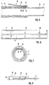
- Fig. 1 shows a partial view suction pipe 1 according to the invention for a vacuum cleaner, comprising an inner tube 2, which in an outer tube 3rd is telescopically included.
- a Handling element 4 is provided in the form of a clamp 5.
- This clamp 5 has a first section 6, which cross-section, see Fig. 3, essentially cylindrical and with its inner diameter only slightly larger than the outside diameter of the Outer tube 3 is selected.
- the clamp 5 is slotted, that is, the first section 6 forms two that Outer tube 3 encompassing more than half the circumference Side arms 31 out.
- the first section 6 is a second Section 7 assigned, which to operate the Handling element and for bringing from a rest position (Fig. 1 or Fig. 3) in a release position (Fig. 4) is pressed.
- FIG. 1 shows a longitudinal section through that in FIG. 1 Suction pipe shown 1.
- Snap-in element 9 formed in one piece, which for engagement in recesses 10 formed on the inner tube, which in shown embodiment are closed on all sides, is trained.
- This locking element 9 is actuated of the second section 7 between a rest position and one release position, since pressing the second Section 7 of the first section 6 of its quasi on the Position the outer tube in a position detached from it Position is brought, whereby the locking element 9th out of engagement with the respective recess 10 brought.
- a locking projection 11 is integrally formed, which in a engages on the outer tube 3 attached recess 12. This locking connection enables the clamp 5 on Outer tube is fixed immovably.
- Fig. 4 shows the clamp 4 in the release position, in which the lock is released and the tubes 2, 3 movable to each other.
- the clamp 4 is in this release position can be brought in that the second section in the direction Arrow A is pressed down on the outer tube 3.
- This causes the first section 6 about the pivot axis X, due to the execution of the clamp 4 in the area of the locking projection 11 lies, at least with its front, the locking element 9 carrying area pivoted upwards is in the position shown in Fig. 4.
- the Locking element 9 from its engagement with the locking recess 10 brought so that the tubes 2, 3, which by itself Known anti-rotation device 16 cannot be rotated relative to one another are held apart or in the longitudinal direction can be pushed into each other.
- FIGS. 1 to 4 Another embodiment of the handling element that essentially that with reference to FIGS. 1 to 4 corresponds to that described, Fig. 5. Also in this Handling element 18, which is also in the form of a clamp 19 is formed, that is on the inner wall 20 Locking element 21 integrally formed.
- This embodiment is dispensed with however, to that envisaged in the above and the Comprehensive projection 11 and the recess 12 Means to set, rather, is a comprehensive axial as well as torsion-proof fixing solely by means of the Latching element 21 realized.
- the outer tube 3 is provided with an opening 22, which is through the liner 13 continues. This opening 22nd is penetrated by the locking element 21, which in the Can engage recesses 10. Since the locking element 21st also in the release position not out of engagement with the Breakthrough device 22 is in this way for a sufficient fixation is ensured.
- FIGS. 6 and 7 reproduced.
- the in Fig. 4 shown anti-rotation 16 dispenses, rather the anti-rotation device is integrated in the top Locking mechanism formed.
- a Inner tube 2 provided in the longitudinal direction groove 23, which the individual recesses 10 with each other connects.
- the depth of this groove 23 is, cf. Fig. 7, deeper dimensioned as the locking recesses 10.
- this embodiment is furthermore a useful pin 25 molded on, which engages in the groove 23.
- the depth of the Groove 23 as well as the length of the useful pin 25 are included dimensioned such that the useful pin 25 is always in engagement with the groove 23 is, even if the locking element in the Was released, that is, if that Locking element 24 out of engagement with the locking recess 10 stands.
- Fig. 8 shows a further embodiment of the Handling element.
- This consists of a lever arm 26, which on a suitable bearing block 27 or the like is pivotally mounted about a pivot axis.
- the locking element 28 projecting.
- an elastic element 32 in the form arranged a coil spring, which is used to generate the Restoring force is used, the lever arm 26 always in the Rest position urges.
- the attachment to the bearing block 27 is elastic, that is, when the Attachment of the lever arm 26 already one sufficiently elastic movement to produce a Restoring force can be applied to the elastic element 32 can also be dispensed with.
- the embodiment can also be chosen such that the bearing block 27 in one piece with the lever arm 26 and on the outer tube 3 accordingly is locked, allowing one accordingly elastic pivotability.
Landscapes
- Engineering & Computer Science (AREA)
- Mechanical Engineering (AREA)
- General Engineering & Computer Science (AREA)
- Electric Vacuum Cleaner (AREA)
- Nozzles For Electric Vacuum Cleaners (AREA)
- Joints Allowing Movement (AREA)
- Quick-Acting Or Multi-Walled Pipe Joints (AREA)
Applications Claiming Priority (2)
| Application Number | Priority Date | Filing Date | Title |
|---|---|---|---|
| DE29619422U | 1996-11-08 | ||
| DE29619422U DE29619422U1 (de) | 1996-11-08 | 1996-11-08 | Teleskopierbares Saugrohr für Staubsauger |
Publications (2)
| Publication Number | Publication Date |
|---|---|
| EP0841033A2 true EP0841033A2 (fr) | 1998-05-13 |
| EP0841033A3 EP0841033A3 (fr) | 1999-04-14 |
Family
ID=8031659
Family Applications (1)
| Application Number | Title | Priority Date | Filing Date |
|---|---|---|---|
| EP97115878A Withdrawn EP0841033A3 (fr) | 1996-11-08 | 1997-09-12 | Tuyau d'aspiration téléscopique pour aspirateur |
Country Status (4)
| Country | Link |
|---|---|
| EP (1) | EP0841033A3 (fr) |
| CN (1) | CN1184622A (fr) |
| DE (1) | DE29619422U1 (fr) |
| PL (1) | PL323022A1 (fr) |
Cited By (5)
| Publication number | Priority date | Publication date | Assignee | Title |
|---|---|---|---|---|
| WO2001045546A1 (fr) * | 1999-12-21 | 2001-06-28 | Kao Corporation | Structure de raccordement de tubes et outil de nettoyage |
| RU2249426C1 (ru) * | 2002-12-31 | 2005-04-10 | Самсунг Гвангджу Электроникс Ко., Лтд. | Стопорное устройство для удлинительной трубки пылесоса |
| EP1537817A1 (fr) * | 2003-12-02 | 2005-06-08 | Samsung Gwangju Electronics Co., Ltd. | Tube de rallonge articulé pour aspirateur |
| RU2351457C2 (ru) * | 2003-12-09 | 2009-04-10 | Анджер Маркетинг Интернэшнл, Ллк | Соединительные элементы (варианты) |
| IT202100017483A1 (it) * | 2021-07-02 | 2023-01-02 | Ams Composites S R L | Dispositivo di bloccaggio selettivo di elementi telescopici |
Families Citing this family (3)
| Publication number | Priority date | Publication date | Assignee | Title |
|---|---|---|---|---|
| DE10120688A1 (de) * | 2001-04-27 | 2002-11-07 | Bsh Bosch Siemens Hausgeraete | Rohrverbindung für ein Saugrohr eines Staubsaugers |
| GB2544104B (en) * | 2015-11-06 | 2018-05-09 | Dyson Technology Ltd | Telescopic wand for a vacuum cleaner |
| CN106617829A (zh) * | 2017-02-08 | 2017-05-10 | 广州视源电子科技股份有限公司 | 移动式支架 |
Family Cites Families (22)
| Publication number | Priority date | Publication date | Assignee | Title |
|---|---|---|---|---|
| DE655488C (de) * | 1936-03-29 | 1938-01-17 | Elektrolux Akt Ges | Aus mindestens zwei ineinander verschiebbaren Rohrteilen bestehende Luftfoerderungsleitung fuer Staubsauger |
| NL60085C (fr) * | 1943-04-09 | 1947-08-15 | ||
| US2484401A (en) * | 1946-03-05 | 1949-10-11 | William R Coie | Crutch |
| US2749153A (en) * | 1953-03-16 | 1956-06-05 | Baker Mfg Co | Spring detent coupling for telescoped parts |
| US2832612A (en) * | 1953-12-04 | 1958-04-29 | Hoover Co | Suction cleaner coupling with spring biased catch |
| US2727762A (en) * | 1954-10-11 | 1955-12-20 | Hoover Co | Tube couplings |
| US3024031A (en) * | 1959-09-04 | 1962-03-06 | Alvin E Davidson | Tool handle adapter socket |
| US3244437A (en) * | 1964-01-28 | 1966-04-05 | Electrolux Corp | Adjustable length vacuum cleaner wand |
| AT359966B (de) * | 1977-10-07 | 1980-12-10 | Famulus Elektrogeraete Gmbh | Einrichtung zum loesbaren verriegeln zweier ineinandergesteckter rohre |
| DE8223754U1 (de) * | 1982-08-23 | 1982-10-07 | Marker, Hannes, 8100 Garmisch-Partenkirchen | Vorrichtung zum Verbinden von teleskopartig stufenweise längenvariablen |
| US4577837A (en) * | 1984-07-30 | 1986-03-25 | Marvin Berg | Locking mechanism for extendible telescoping tubular members |
| US4669755A (en) * | 1986-09-29 | 1987-06-02 | The Singer Company | Hose connection for vacuum cleaner attachments |
| US4978244A (en) * | 1988-03-02 | 1990-12-18 | Interlock Structures International, Inc. | Fastener apparatus |
| DE3807028C1 (en) * | 1988-03-04 | 1989-09-07 | Heidemann-Werke Gmbh & Co Kg, 3352 Einbeck, De | Telescopic tube connection |
| DE3929399A1 (de) * | 1989-09-05 | 1991-03-21 | Heidemann Werke | Teleskopierbare rohrverbindung |
| DE3931639C2 (de) * | 1989-09-22 | 1999-12-16 | Miele & Cie | Rohrsteckverbindung zwischen einem Innenrohr und einem Außenrohr mit einer lösbaren Rohrverriegelung |
| SE464928B (sv) * | 1989-11-01 | 1991-07-01 | Electrolux Ab | Anordning foer inboerdes fixering av i varandra teleskopiskt foerskjutbara roer |
| DE9107725U1 (de) * | 1991-06-22 | 1991-09-12 | Marker, Hannes, 8100 Garmisch-Partenkirchen | Teleskoprohrvorrichtung, insbesondere Teleskop-Gabelbaum |
| DE4201855C2 (de) * | 1992-01-24 | 1998-06-04 | Aeg Hausgeraete Gmbh | Saugschlauch |
| DE9213813U1 (de) * | 1992-10-13 | 1994-02-10 | Siemens AG, 80333 München | Rohrverbindung |
| DE4309495A1 (de) * | 1993-03-24 | 1994-09-29 | Licentia Gmbh | Staubsaugerschlauch |
| DE19524290C1 (de) * | 1995-07-06 | 1996-08-14 | Froh Roehren | Teleskopierbares Staubsauger-Saugrohr |
-
1996
- 1996-11-08 DE DE29619422U patent/DE29619422U1/de not_active Expired - Lifetime
-
1997
- 1997-09-12 EP EP97115878A patent/EP0841033A3/fr not_active Withdrawn
- 1997-11-06 CN CN97122425A patent/CN1184622A/zh active Pending
- 1997-11-06 PL PL32302297A patent/PL323022A1/xx unknown
Cited By (7)
| Publication number | Priority date | Publication date | Assignee | Title |
|---|---|---|---|---|
| WO2001045546A1 (fr) * | 1999-12-21 | 2001-06-28 | Kao Corporation | Structure de raccordement de tubes et outil de nettoyage |
| US7004671B2 (en) | 1999-12-21 | 2006-02-28 | Kao Corporation | Pipe connecting structure and cleaning tool |
| US7300077B2 (en) | 1999-12-21 | 2007-11-27 | Kao Corporation | Pipe connecting structure |
| RU2249426C1 (ru) * | 2002-12-31 | 2005-04-10 | Самсунг Гвангджу Электроникс Ко., Лтд. | Стопорное устройство для удлинительной трубки пылесоса |
| EP1537817A1 (fr) * | 2003-12-02 | 2005-06-08 | Samsung Gwangju Electronics Co., Ltd. | Tube de rallonge articulé pour aspirateur |
| RU2351457C2 (ru) * | 2003-12-09 | 2009-04-10 | Анджер Маркетинг Интернэшнл, Ллк | Соединительные элементы (варианты) |
| IT202100017483A1 (it) * | 2021-07-02 | 2023-01-02 | Ams Composites S R L | Dispositivo di bloccaggio selettivo di elementi telescopici |
Also Published As
| Publication number | Publication date |
|---|---|
| CN1184622A (zh) | 1998-06-17 |
| DE29619422U1 (de) | 1998-03-12 |
| PL323022A1 (en) | 1998-05-11 |
| EP0841033A3 (fr) | 1999-04-14 |
Similar Documents
| Publication | Publication Date | Title |
|---|---|---|
| DE102016105767B4 (de) | Endoskopsteuervorrichtung und Endoskop | |
| DE2149278B2 (de) | Vorrichtung zur Längenverstellbarkeit einer Bowdenzughülle | |
| DE1931732A1 (de) | Fernbedienungseinrichtung | |
| DE202004002321U1 (de) | Positioniervorrichtung für eine Mehrsegment-Gleitschieneneinrichtung für Schubladen | |
| EP0732893B1 (fr) | Instrument chirurgical tubulaire | |
| EP0841033A2 (fr) | Tuyau d'aspiration téléscopique pour aspirateur | |
| DE69711405T3 (de) | Regelknopf für haushaltgeräte | |
| EP1229258A2 (fr) | Mousqueton constitué d'un corps muni d'une ouverture d'accès | |
| WO2001029453A1 (fr) | Dispositif de changement de vitesses comprenant un levier de changement de vitesses pour la boite de vitesses automatique d'un vehicule automobile | |
| DE202014100778U1 (de) | Betätigungsvorrichtung für eine Feststellbremse | |
| DE69001348T2 (de) | Verbindung zwischen tuergriff und betaetigungsstange eines kfz-tuerschlosses. | |
| EP0686552A2 (fr) | Poignée tournante pour le changement de vitesse de bicyclette | |
| DE10120688A1 (de) | Rohrverbindung für ein Saugrohr eines Staubsaugers | |
| DE8509585U1 (de) | Vorrichtung zur Aufnahme bzw. zum Aufwickeln einer Leine, insbesondere Hundeleine (I) | |
| DE102004028737A1 (de) | Betätigungssystem für eine Handbremse | |
| DE102020215084A1 (de) | Stangenmontierbare Haltevorrichtung und sanitäre Handbrausenhalteeinrichtung | |
| DE2845485A1 (de) | Einstellvorrichtung mit einem um eine achse schwenkbaren einstellorgan | |
| DE3315928C2 (de) | Traggehäuse für Tiergurtleinen | |
| EP1649111B1 (fr) | Dispositif de retenue pour une douche | |
| DE10051452B4 (de) | Anordnung zur Anbringung einer Brause | |
| AT398701B (de) | Skibindung mit einem fersenteil | |
| DE102017117655A1 (de) | Zweiradständer | |
| EP2110208A1 (fr) | Tige de télescope dotée d'un dispositif d'arrêt | |
| DE202007000779U1 (de) | Schnellspannhalter für elektronische oder opto-elektronische Geräte | |
| DE202009001163U1 (de) | Sportstock |
Legal Events
| Date | Code | Title | Description |
|---|---|---|---|
| PUAI | Public reference made under article 153(3) epc to a published international application that has entered the european phase |
Free format text: ORIGINAL CODE: 0009012 |
|
| AK | Designated contracting states |
Kind code of ref document: A2 Designated state(s): DE ES FR GB IT |
|
| AX | Request for extension of the european patent |
Free format text: AL;LT;LV;RO;SI |
|
| PUAL | Search report despatched |
Free format text: ORIGINAL CODE: 0009013 |
|
| AK | Designated contracting states |
Kind code of ref document: A3 Designated state(s): AT BE CH DE DK ES FI FR GB GR IE IT LI LU MC NL PT SE |
|
| AX | Request for extension of the european patent |
Free format text: AL;LT;LV;RO;SI |
|
| 17P | Request for examination filed |
Effective date: 19990507 |
|
| AKX | Designation fees paid |
Free format text: DE ES FR GB IT |
|
| STAA | Information on the status of an ep patent application or granted ep patent |
Free format text: STATUS: THE APPLICATION IS DEEMED TO BE WITHDRAWN |
|
| 18D | Application deemed to be withdrawn |
Effective date: 20000401 |