EP0841133B1 - Rotationsschneidmaschine mit einer Vorrichtung zur Druckkraftregelung - Google Patents
Rotationsschneidmaschine mit einer Vorrichtung zur Druckkraftregelung Download PDFInfo
- Publication number
- EP0841133B1 EP0841133B1 EP97119358A EP97119358A EP0841133B1 EP 0841133 B1 EP0841133 B1 EP 0841133B1 EP 97119358 A EP97119358 A EP 97119358A EP 97119358 A EP97119358 A EP 97119358A EP 0841133 B1 EP0841133 B1 EP 0841133B1
- Authority
- EP
- European Patent Office
- Prior art keywords
- rotor
- knife
- plain
- pressure
- rotary cutter
- Prior art date
- Legal status (The legal status is an assumption and is not a legal conclusion. Google has not performed a legal analysis and makes no representation as to the accuracy of the status listed.)
- Expired - Lifetime
Links
- 230000007246 mechanism Effects 0.000 claims abstract description 66
- 239000000463 material Substances 0.000 claims abstract description 9
- 239000000123 paper Substances 0.000 description 17
- 238000010586 diagram Methods 0.000 description 3
- 230000008602 contraction Effects 0.000 description 2
- 238000005070 sampling Methods 0.000 description 2
- 239000000919 ceramic Substances 0.000 description 1
- 235000019504 cigarettes Nutrition 0.000 description 1
- 238000010276 construction Methods 0.000 description 1
- 230000001419 dependent effect Effects 0.000 description 1
- 239000000428 dust Substances 0.000 description 1
- 239000012530 fluid Substances 0.000 description 1
- 238000003780 insertion Methods 0.000 description 1
- 230000037431 insertion Effects 0.000 description 1
- 239000012212 insulator Substances 0.000 description 1
- 230000005291 magnetic effect Effects 0.000 description 1
- 238000004519 manufacturing process Methods 0.000 description 1
- 238000000034 method Methods 0.000 description 1
- 239000011087 paperboard Substances 0.000 description 1
- 230000001953 sensory effect Effects 0.000 description 1
- 239000007779 soft material Substances 0.000 description 1
- 229920003002 synthetic resin Polymers 0.000 description 1
- 239000000057 synthetic resin Substances 0.000 description 1
Images



Classifications
-
- B—PERFORMING OPERATIONS; TRANSPORTING
- B26—HAND CUTTING TOOLS; CUTTING; SEVERING
- B26D—CUTTING; DETAILS COMMON TO MACHINES FOR PERFORATING, PUNCHING, CUTTING-OUT, STAMPING-OUT OR SEVERING
- B26D7/00—Details of apparatus for cutting, cutting-out, stamping-out, punching, perforating, or severing by means other than cutting
- B26D7/26—Means for mounting or adjusting the cutting member; Means for adjusting the stroke of the cutting member
- B26D7/2628—Means for adjusting the position of the cutting member
- B26D7/265—Journals, bearings or supports for positioning rollers or cylinders relatively to each other
-
- B—PERFORMING OPERATIONS; TRANSPORTING
- B26—HAND CUTTING TOOLS; CUTTING; SEVERING
- B26D—CUTTING; DETAILS COMMON TO MACHINES FOR PERFORATING, PUNCHING, CUTTING-OUT, STAMPING-OUT OR SEVERING
- B26D7/00—Details of apparatus for cutting, cutting-out, stamping-out, punching, perforating, or severing by means other than cutting
- B26D7/26—Means for mounting or adjusting the cutting member; Means for adjusting the stroke of the cutting member
- B26D7/2628—Means for adjusting the position of the cutting member
-
- Y—GENERAL TAGGING OF NEW TECHNOLOGICAL DEVELOPMENTS; GENERAL TAGGING OF CROSS-SECTIONAL TECHNOLOGIES SPANNING OVER SEVERAL SECTIONS OF THE IPC; TECHNICAL SUBJECTS COVERED BY FORMER USPC CROSS-REFERENCE ART COLLECTIONS [XRACs] AND DIGESTS
- Y10—TECHNICAL SUBJECTS COVERED BY FORMER USPC
- Y10T—TECHNICAL SUBJECTS COVERED BY FORMER US CLASSIFICATION
- Y10T83/00—Cutting
- Y10T83/141—With means to monitor and control operation [e.g., self-regulating means]
- Y10T83/148—Including means to correct the sensed operation
-
- Y—GENERAL TAGGING OF NEW TECHNOLOGICAL DEVELOPMENTS; GENERAL TAGGING OF CROSS-SECTIONAL TECHNOLOGIES SPANNING OVER SEVERAL SECTIONS OF THE IPC; TECHNICAL SUBJECTS COVERED BY FORMER USPC CROSS-REFERENCE ART COLLECTIONS [XRACs] AND DIGESTS
- Y10—TECHNICAL SUBJECTS COVERED BY FORMER USPC
- Y10T—TECHNICAL SUBJECTS COVERED BY FORMER US CLASSIFICATION
- Y10T83/00—Cutting
- Y10T83/141—With means to monitor and control operation [e.g., self-regulating means]
- Y10T83/148—Including means to correct the sensed operation
- Y10T83/152—And modify another operation
-
- Y—GENERAL TAGGING OF NEW TECHNOLOGICAL DEVELOPMENTS; GENERAL TAGGING OF CROSS-SECTIONAL TECHNOLOGIES SPANNING OVER SEVERAL SECTIONS OF THE IPC; TECHNICAL SUBJECTS COVERED BY FORMER USPC CROSS-REFERENCE ART COLLECTIONS [XRACs] AND DIGESTS
- Y10—TECHNICAL SUBJECTS COVERED BY FORMER USPC
- Y10T—TECHNICAL SUBJECTS COVERED BY FORMER US CLASSIFICATION
- Y10T83/00—Cutting
- Y10T83/465—Cutting motion of tool has component in direction of moving work
- Y10T83/4766—Orbital motion of cutting blade
- Y10T83/4795—Rotary tool
- Y10T83/483—With cooperating rotary cutter or backup
- Y10T83/4836—With radial overlap of the cutting members
-
- Y—GENERAL TAGGING OF NEW TECHNOLOGICAL DEVELOPMENTS; GENERAL TAGGING OF CROSS-SECTIONAL TECHNOLOGIES SPANNING OVER SEVERAL SECTIONS OF THE IPC; TECHNICAL SUBJECTS COVERED BY FORMER USPC CROSS-REFERENCE ART COLLECTIONS [XRACs] AND DIGESTS
- Y10—TECHNICAL SUBJECTS COVERED BY FORMER USPC
- Y10T—TECHNICAL SUBJECTS COVERED BY FORMER US CLASSIFICATION
- Y10T83/00—Cutting
- Y10T83/465—Cutting motion of tool has component in direction of moving work
- Y10T83/4766—Orbital motion of cutting blade
- Y10T83/4795—Rotary tool
- Y10T83/483—With cooperating rotary cutter or backup
- Y10T83/4838—With anvil backup
- Y10T83/4841—With resilient anvil surface
-
- Y—GENERAL TAGGING OF NEW TECHNOLOGICAL DEVELOPMENTS; GENERAL TAGGING OF CROSS-SECTIONAL TECHNOLOGIES SPANNING OVER SEVERAL SECTIONS OF THE IPC; TECHNICAL SUBJECTS COVERED BY FORMER USPC CROSS-REFERENCE ART COLLECTIONS [XRACs] AND DIGESTS
- Y10—TECHNICAL SUBJECTS COVERED BY FORMER USPC
- Y10T—TECHNICAL SUBJECTS COVERED BY FORMER US CLASSIFICATION
- Y10T83/00—Cutting
- Y10T83/465—Cutting motion of tool has component in direction of moving work
- Y10T83/4766—Orbital motion of cutting blade
- Y10T83/4795—Rotary tool
- Y10T83/483—With cooperating rotary cutter or backup
- Y10T83/4844—Resiliently urged cutter or anvil member
-
- Y—GENERAL TAGGING OF NEW TECHNOLOGICAL DEVELOPMENTS; GENERAL TAGGING OF CROSS-SECTIONAL TECHNOLOGIES SPANNING OVER SEVERAL SECTIONS OF THE IPC; TECHNICAL SUBJECTS COVERED BY FORMER USPC CROSS-REFERENCE ART COLLECTIONS [XRACs] AND DIGESTS
- Y10—TECHNICAL SUBJECTS COVERED BY FORMER USPC
- Y10T—TECHNICAL SUBJECTS COVERED BY FORMER US CLASSIFICATION
- Y10T83/00—Cutting
- Y10T83/768—Rotatable disc tool pair or tool and carrier
- Y10T83/7809—Tool pair comprises rotatable tools
- Y10T83/783—Tool pair comprises contacting overlapped discs
- Y10T83/7843—With means to change overlap of discs
-
- Y—GENERAL TAGGING OF NEW TECHNOLOGICAL DEVELOPMENTS; GENERAL TAGGING OF CROSS-SECTIONAL TECHNOLOGIES SPANNING OVER SEVERAL SECTIONS OF THE IPC; TECHNICAL SUBJECTS COVERED BY FORMER USPC CROSS-REFERENCE ART COLLECTIONS [XRACs] AND DIGESTS
- Y10—TECHNICAL SUBJECTS COVERED BY FORMER USPC
- Y10T—TECHNICAL SUBJECTS COVERED BY FORMER US CLASSIFICATION
- Y10T83/00—Cutting
- Y10T83/768—Rotatable disc tool pair or tool and carrier
- Y10T83/7809—Tool pair comprises rotatable tools
- Y10T83/7851—Tool pair comprises disc and cylindrical anvil
- Y10T83/7855—With adjustable means to urge tool elements together
Definitions
- the present invention relates to a rotary cutter for cutting consecutively such sheet material as paper strip, paper board, synthetic resin film, etc. into pieces with desired length according to the preamble of claim 1 (see, for example, JP-A-06 304 895).
- the sheet product such as paper, film, etc., includes a group of flat product and another group of roll product.
- the flat product is formed by cutting the product supplied from a sheet manufacturing line or the roll product in the feeding direction and the width direction of the product with a slitter and a fly knife in a cutter or a sheeter.
- a slitter employing the type of thin upper and lower blades produces little paper dust even in cutting the paper of 600g /m2.
- a fly knife In the type with one fixed blade shown in Fig. 4 of attached drawings, for example, a paper sheet 1 is cut by a fixed blade 2 and a rotating blade 3, but this type has not enough power for cutting a thick paper.
- a twin rotor type with an upper and a lower rotating blades shown in Fig. 5 has been developed and is in main use at present. In this twin rotor type, however, an adjusting operation for matching relative positions of the upper and the lower rotating blades is so difficult that even a skilled worker needs six to eight hours for the blade position matching in some cases.
- the rotary cutter comprises a knife rotor 6, a plain rotor 7, and a feed roller 8.
- the knife rotor 6 have knives 9a, 9b which are mounted on the two portions of outer surface of said knife rotor and arranged in the longitudinal direction of the knife rotor.
- the paper sheet 1 which is sandwiched between and fed from the plain rotor 7 driven by a variable speed motor and the feed roller 8 is cut by the knife 9a attached to the outer surface of the,knife rotor 6 driven by a servo motor while the paper 1 being pressed against the plain rotor 7.
- the knife rotor 6 is controlled and driven so as to rotate at the same speed with that of the fed paper 1 only when the attached knives 9a, 9b contact the paper 1 to be cut.
- a holding mechanism of the respective knives 9a, 9b in the knife rotor 6 is, for example, as shown in an enlarged partial sectional view of Fig. 7.
- the knife 9a is attached to the knife rotor 6 as follows. At first, a knife holder 12 equipped with a permanent magnet 11 is fixed by a bolt 13 into a groove 10 formed in the longitudinal direction of the knife rotor 6, and then, into an insertion groove 14 formed consequently, the knife 9a is simply inserted, and, as a result, the knife can be fixed to the knife rotor 6 due to the magnetic effect. Accordingly, the knife replacement service can be carried out within a few seconds and the period for knife replacement has surprisingly been reduced.
- EP-A-0 016 615 discloses a cutting head for a cigarette filter attachment machine for cutting a filter attachment web at regular intervals in co-operation with a cutting drum, comprising a rotary member which carries one or more knives and is mounted on a movable carrier so as to be movable towards and away from the cutting drum, and including a fluid powered actuator which is arranged to urge the cutting head towards the cutting drum.
- a rotary cutter for cutting a sheet material consecutively into pieces with predetermined length, said rotary cutter comprising: a knife rotor equipped with at least one knife on its outer surface in the longitudinal direction of said knife rotor, a plain rotor disposed parallel to said knife rotor so that the outer surface of said plain rotor almost comes in contact with a blade edge of said knife on said knife rotor, a clearance adjusting mechanism for adjusting a clearance between said knife and said plain rotor, said adjusting mechanism being installed in connection with support mechanisms and bearing boxes disposed on both end portions of said knife rotor and said plain rotor, respectively, said clearance adjusting mechanism comprising a toggle mechanism rotatably connected to end portions of the bearing boxes, while another end portion of a bearing box rotatably supports the another end portion of the other bearing box, and pushing means for acting on said toggle mechanism to change an amount by which said toggle mechanism is pushed to adjust the clearance between said knife and said plain rotor, means for moving the knife rotor and
- said pressure signal generating means is a pressure sensor which detects a pressure working between said toggle mechanism and said pushing means.
- Fig. 1 is a schematic view illustrating a diagrammatic constitution of a rotary cutter equipped with a contact pressure control device of an embodiment of the present invention.
- the rotary cutter of the embodiment comprises a knife rotor 30 equipped with at least one knife 20 on its outer surface in the longitudinal direction and a plain rotor 40 disposed parallel to said knife rotor 30 so as for the outer surface of said plain rotor 40 to almost come in contact with a blade edge of said knife 20 on said knife rotor 30.
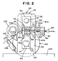
- Fig. 2 is a side elevation view illustrating a detailed structure of a bearing box support mechanism and a clearance adjusting mechanism of a knife rotor 30 and a plain rotor 40 of the rotary cutter shown in Fig. 1.
- the bearing box support mechanism and the clearance adjusting mechanism similar structures are employed in either sides of the knife rotor 30 and the plain rotor 40 respectively, and, therefore, the explanation will be developed hereinafter only for that disposed in one side. Referring to the bearing box support mechanism , as shown in Fig.
- an end portion 42a of a plain rotor bearing box 42 to support rotatably an end portion of a rotary shaft 41 of the plain rotor 40 supports rotatably an end portion 32a of a knife rotor bearing box 32 to support rotatably an end portion of a rotary shaft 31 of the knife rotor 30, and another end portion 42b of the plain rotor bearing box 42 supports another end portion 32b of the knife rotor bearing box 32 through a toggle mechanism 50.
- a bearing box pre-loading mechanism is composed of the support member 43, the support member 33 and the air spring 60, and, in some case, the air spring 60 may be replaced by an air cylinder, a hydraulic cylinder or a coil spring, and the bearing box pre-loading mechanism may be connected directly to the knife rotor 30 and the plain rotor 40.
- the bearing box pre-loading mechanism gives a pressure onto the end portions of the rotary shaft 31 of the knife rotor 30 and the rotary shaft 41 of the plain rotor 40 so that the knife rotor bearing box 32 and the plain rotor bearing box 42 move into the opposite directions with each other.
- the clearance adjusting mechanism is composed of the toggle mechanism 50 which is used also as a member of the bearing box support mechanism, a motor 80, a gear box 81 which has high reduction gear ratio and is driven by said rotor 80, and a threaded member 82 with a micro-pitch thread which is driven by said gear box 81.
- the gear box 81 is fixed to the knife rotor bearing box 32 by a proper channel member 81a.
- a toggle joint fitting 51 is moved by rotating the threaded member 82 engaged with the toggle mechanism 50 and the distance between the end portion 42b of the plain rotor bearing box 42 and the end portion 32b of the knife rotor bearing box 32 is changed.
- the threaded member 82 is screwed-in to push the toggle joint fitting 51 forward, and the knife rotor bearing box 32 and the knife rotor 30 are moved downward to make the clearance narrower.
- the threaded member 82 is screwed-out to move the toggle joint fitting 51 backward and the knife rotor 30 is moved upward.
- the toggle joint fitting 51 of the toggle mechanism 50 always push the threaded member 82, so that it is not necessary to connect the toggle joint fitting 51 and the threaded member 82 with each other.
- the gear box 81 can be installed independently from the toggle mechanism 50.
- the travel of the threaded member 82 can be measured accurately by a rotary encoder 90 which is installed on the end portion of the threaded member 82.
- the clearance between the knife 20 and the plain rotor 40 can be adjusted in microns within the range of -0.5 to +1.5 mm with a reference point where the knife 20 comes into contact with the plain rotor 40.
- each plain rotor bearing box 42 is fixed on a frame 100 and to the plain rotor bearing box 42 is connected a rotary encoder 101, so that the number of revolution can be measured continuously by said rotary encoder 101.
- a feed roller 102 is supported rotatably by a bearing box 103 and another end portion of said bearing box 103 is pressed by an expansion force of an air cylinder 104 an end of which is supported rotatably by the plain rotor bearing box 42, so that said feed roller 102 is brought into contact with the outer surface of the plain rotor 40 with a certain loading.
- the feed roller 102 rotates as the plain rotor 40 does and the outer surface of the feed roller 102 is covered by a soft material to prevent it from slipping.
- the pressure sensor 110 is attached between the toggle joint fitting 51 and the threaded member 82 by a sensor case 111 as shown in Fig. 3.
- the pressure sensor 110 may be an appropriate piezoelectric element and is kept isolated from the sensor case 111 by a pair of electrode insulator 112.
- the contact pressure control device of this embodiment is equipped with said pressure sensor 110 attached to the rotary cutter and a circuit 200 for adjusting a contact pressure automatically (hereafter, referred to as contact pressure adjusting circuit) which is connected to the clearance adjusting circuit.
- the contact pressure adjusting circuit 200 comprises a circuit 200A for controlling an operation of a clearance adjusting mechanism installed on the right end portion of the rotary cutter and a circuit 200B for controlling an operation of another clearance adjusting mechanism installed on the left end portion of the rotary cutter.
- Each of these circuits, 200A and 200B may have similar construction with each other, and, in this embodiment, comprises an amplifier 201, an indicator 202, a comparator 203, a setting device 204, a driver for a driving portion 205 (hereafter referred to as the driver), and an amplifier for peak holding 206 (hereafter referred to as the peak holding amplifier).
- the peak holding amplifier 206 of the circuit 200A holds a peak value of the pressure signal which is detected by the pressure sensor 110 disposed in the clearance adjusting mechanism of the right end portion of Fig. 1 while the paper sheet 1 being cut by the knife 20 and transmits it to the amplifier 201.
- the amplifier 201 receives and amplifies said instantaneous peak value of the pressure signal and indicates it on the indicator 202 and transmits it to the comparator 203.
- the comparator 203 compares the pressure signal transmitted from the amplifier 201 with a set value of the contact pressure set by the setting device 204.
- the motor 80 of the clearance adjusting mechanism of the right end portion When the pressure signal transmitted from the amplifier 201 is higher than the set value of the contact pressure (desired value), the motor 80 of the clearance adjusting mechanism of the right end portion is actuated through the driver 205 so that the threaded member 82 is moved backward and the clearance between the knife 20 and plain rotor 40 is made wider automatically.
- the motor 80 of the clearance adjusting mechanism of the right end portion When the pressure signal transmitted from the amplifier 201 is lower than the set value of the contact pressure (desired value), the motor 80 of the clearance adjusting mechanism of the right end portion is rotated in the reverse direction through the driver 205 so that the threaded member 82 is moved forward and the clearance between the knife 20 and plain rotor 40 is made narrower automatically.
- the circuit 200B for the clearance adjusting mechanism of the left end portion actuates the clearance adjusting mechanism of the left end portion in the same automatic adjusting manner as the circuit 200A does for the clearance adjusting mechanism of the right end portion as described above.
- the contact pressure control device of this embodiment allows a contact pressure values of the knife 20 and the plain rotor 40 to be automatically and easily adjusted to the desired value by detecting the applied load values, namely instantaneous pressure value, to the right end portion and the left end portion of the knife rotor 30 and the plain rotor 40 while the paper sheet being cut by the knife 20, by comparing them with the desired pressure value, and then by actuating each of the clearance adjusting mechanisms disposed in the right end portion and the left end portion respectively in response to each result of comparison.
- the contact pressure adjusting circuit 200 of the above embodiment is composed only of a plurality of hardware, these kinds of circuit to adjust a contact pressure automatically can be also made up of a sequencer, a micro-computer system, a personal computer.
- the above embodiment employs a peak pressure value applied to the pressure sensor 110 as a representative value of the contact pressure by the use of the peak holding amplifier 206
- the present invention is not restricted to the details of this description.
- the whole output signal from the pressure sensor 110 may be used by sampling the values in several points without limitation on whether it being the peak value or not and taking an average thereof as the pressure value by the use of an appropriate sampling holding circuit as a substitute for the peak holding amplifier 206.
- the pressure sensor 110 detects the load applied to the threaded member 82 through the toggle mechanism 50
- the present invention is not restricted to that system but allows similar pressure sensor to be disposed on the relative portion of the bearing box support mechanism, for example, on the portion where the load can be detected which is applied to the bearing box 42, to the end portion 42a of the plain rotor bearing box 42, or to the end portion 32a of the knife rotor 32.
- the piezoelectric element made of ceramics and the like is used as the pressure sensor 110, any kind of detecting element may be used also, so far as it can detect the load applied to the portion mentioned above.
- the above embodiment makes it possible to adjust the contact pressure full-automatically by providing the contact pressure adjusting circuit 200, but the present invention is not limited to this system.
- the personal computer and the like may be used in place of the contact pressure adjusting circuit 200.
- the values of the load applied to the bearing box support mechanism or the clearance adjusting mechanism of the right end portion and the left end portion while the paper sheet being cut by the knife are transmitted to the personal computer through the peak holding amplifier 206. Then, these load values are indicated on the CRT of the personal computer.
- the operator may determine the correcting values from the load values indicated on the CRT and input them from the keyboard of the personal computer.
- the motor 80 of the corresponding portion of the clearance adjusting mechanism is actuated to control the feed amount of the toggle mechanism 50 by the thread on the threaded member 82, so that the contact pressure can be easily adjusted to the desired value.
- the contact pressure adjustment of the knife of rotary cutter can be accomplished easily and quickly with numerical controlling without traditional sensory controlling. Even if the rotary cutter is driven for long time, the change in contact pressure which may be caused by the wear of knife itself and the variation in size resulting from the expansion and contraction of the surrounding mechanical components can be compensated easily and quickly.
Landscapes
- Life Sciences & Earth Sciences (AREA)
- Forests & Forestry (AREA)
- Engineering & Computer Science (AREA)
- Mechanical Engineering (AREA)
- Details Of Cutting Devices (AREA)
- Nonmetal Cutting Devices (AREA)
- Constituent Portions Of Griding Lathes, Driving, Sensing And Control (AREA)
- Crushing And Grinding (AREA)
- Finish Polishing, Edge Sharpening, And Grinding By Specific Grinding Devices (AREA)
Claims (2)
- Rotations- bzw. rundlaufende Schneidmaschine zum aufeinanderfolgenden Schneiden eines Blatt- bzw. Folienmaterials (1) in Teile mit vorbestimmter Länge, wobei die Rotations-Schneidmaschine aufweist:dadurch gekennzeichnet, dass die Rotations-Schneidmaschine weiterhin eine Kontaktdruck-Steuer- bzw. -Regelvorrichtung (110, 200) zum Steuern bzw. Regeln eines Kontaktdrucks des an dem Messerrotor (30) angebrachten Messers (20) gegen den Glattrotor (40) aufweist,einen Messerrotor (30), der an seiner Außenseite bzw. -fläche mit wenigstens einem Messer (20) in der Längsrichtung des Messerrotors (30) ausgerüstet ist,einen Glattrotor (40), der zu dem Messerrotor (30) in der Weise parallel angeordnet ist, dass die Außenseite des Glattrotors (40) beinahe in Kontakt mit einer Klingen- bzw. Schneidkante des Messers (20) an dem Messerrotor (30) kommt,einen Spieleinstellmechanismus (50, 60, 70, 80, 81, 82) zum Einstellen eines Spiels zwischen dem Messer (20) und dem Glattrotor (40), wobei der Einstellmechanismus (50, 60, 70, 80, 81, 82) in Verbindung mit Stütz- bzw. Tragmechanismen (33, 43) und Lagerkörpern (32, 42) installiert bzw. eingebaut ist, welche an beiden Endbereichen des Messerrotors (30) und des Glattrotors (40) entsprechend angeordnet sind, wobei der Spieleinstellmechanismus (50, 60, 70, 80, 81, 82) aufweist: einen Kniehebelmechanismus (50), der mit einem jeweiligen Endbereich (32b, 42b) der Lagerkörper (32, 42) drehbar bzw. rotierbar verbunden ist, wohingegen ein anderer Endbereich (42a) eines Lagerkörpers (42) den anderen Endbereich (32a) des anderen Lagerkörpers (32) drehbar bzw. rotierbar lagert, und Drückmittel (80, 81, 82), um auf den Kniehebelmechanismus (50) einzuwirken, um ein Ausmaß bzw. einen Betrag zu ändern, um den der Kniehebelmechanismus (50) gedrückt wird, um den Spielraum zwischen dem Messer (20) und dem Glattrotor (40) einzustellen, undein Mittel (60) zum Bewegen des Messerrotors (30) und des Glattrotors (40) relativ zueinander,
wobei die Kontaktdrucksteuer- bzw. -regelvorrichtung aufweist:Drucksignalerzeugungsmittel (110), die zwischen dem Kniehebelmechanismus (50) und dem Drückmittel (80, 81, 82) angeordnet sind, um einen auf den Spieleinstellmechanismus (50, 60, 70, 80, 81, 82) wirkenden Druck zu detektieren, während das Blatt- bzw. Folienmaterial (1) geschnitten wird, und um ein Drucksignal zu erzeugen, das den Druck anzeigt;ein Drucksignalanzeigemittel (201, 202) zum Anzeigen des Drucksignals, das von jedem Drucksignalerzeugungsmittel (110) zu einem Operator bzw. einer Bedienungsperson übertragen wird; und ein Betätigungsmittel, um es der Bedienungsperson zu erlauben, das Drückmittel (80, 81, 82) auf der Grundlage eines Drucksignals zu betätigen, das durch das Drucksignalanzeigemittel (201, 202) angezeigt wird. - Rotations-Schneidmaschine, wie in Anspruch 1 beansprucht, bei der das Drucksignalerzeugungsmittel (110) ein Drucksensor (110) ist, der einen zwischen dem Kniehebelmechanismus (50) und dem Drückmittel (80, 81, 82) wirkenden Druck detektiert.
Applications Claiming Priority (3)
| Application Number | Priority Date | Filing Date | Title |
|---|---|---|---|
| JP8293561A JP2883862B2 (ja) | 1996-11-06 | 1996-11-06 | ロータリーカッターのための接圧制御方法および装置 |
| JP29356196 | 1996-11-06 | ||
| JP293561/96 | 1996-11-06 |
Publications (2)
| Publication Number | Publication Date |
|---|---|
| EP0841133A1 EP0841133A1 (de) | 1998-05-13 |
| EP0841133B1 true EP0841133B1 (de) | 2002-10-16 |
Family
ID=17796349
Family Applications (1)
| Application Number | Title | Priority Date | Filing Date |
|---|---|---|---|
| EP97119358A Expired - Lifetime EP0841133B1 (de) | 1996-11-06 | 1997-11-05 | Rotationsschneidmaschine mit einer Vorrichtung zur Druckkraftregelung |
Country Status (5)
| Country | Link |
|---|---|
| US (1) | US6158316A (de) |
| EP (1) | EP0841133B1 (de) |
| JP (1) | JP2883862B2 (de) |
| AT (1) | ATE226128T1 (de) |
| DE (1) | DE69716377T2 (de) |
Cited By (1)
| Publication number | Priority date | Publication date | Assignee | Title |
|---|---|---|---|---|
| US7001477B2 (en) | 2003-12-02 | 2006-02-21 | Kimberly-Clark Worldwide, Inc. | Cutting method and apparatus having an affixed knife |
Families Citing this family (19)
| Publication number | Priority date | Publication date | Assignee | Title |
|---|---|---|---|---|
| IT1299877B1 (it) * | 1998-03-05 | 2000-04-04 | Gd Spa | Metodo ed unita' per la lavorazione di materiale in foglio. |
| US6418828B1 (en) * | 1999-06-24 | 2002-07-16 | The Procter & Gamble Company | Force-adjustable rotary apparatus for working webs or sheets of material |
| FR2826894B1 (fr) * | 2001-07-04 | 2003-09-19 | Eastman Kodak Co | Procede de rectification et dispositif de controle d'un arbre de coupe |
| US6742427B2 (en) | 2001-12-13 | 2004-06-01 | John R. Buta | Helical rotary drum shears |
| US6845698B2 (en) * | 2002-02-25 | 2005-01-25 | Ppg Industries Ohio, Inc. | Systems and methods for severing elongated material |
| DE102005022604A1 (de) * | 2005-05-11 | 2006-11-16 | Aichele Werkzeuge Gmbh | Rotationsschneidvorrichtung, Verfahren zur Außerbetriebnahme einer Rotationsschneidvorrichtung und Verfahren zum Betrieb einer Rotationsschneidvorrichtung |
| DE102005060578A1 (de) * | 2005-12-17 | 2007-06-21 | Bikoma Ag Spezialmaschinen | Vorrichtung zum Rotationsschneiden |
| DE102006051359A1 (de) * | 2006-10-27 | 2008-04-30 | Khs Ag | Schneidwerk für ein Etikettieraggregat sowie Etikettieraggregat mit einem solchen Schneidwerk |
| DE102007058819A1 (de) * | 2007-12-05 | 2009-06-10 | Krones Ag | Vorrichtung zum Schneiden von Etiketten |
| JP5202060B2 (ja) * | 2008-03-24 | 2013-06-05 | 三菱重工印刷紙工機械株式会社 | スリッタ刃の高さ調整方法及び装置 |
| WO2011088069A1 (en) * | 2010-01-12 | 2011-07-21 | Wadsworth Lewis W | Apparatus and method for cutting tubular members |
| JP5502505B2 (ja) * | 2010-01-26 | 2014-05-28 | 旭マシナリー株式会社 | クロスカッター装置 |
| DE102013110510A1 (de) * | 2013-09-23 | 2015-03-26 | Rototechnix Sas | Vorrichtung zum Rotationsstanzen |
| JP6173208B2 (ja) * | 2013-12-27 | 2017-08-02 | サントリー食品インターナショナル株式会社 | ロールラベラ用カッタユニット |
| KR102790886B1 (ko) * | 2019-05-09 | 2025-04-04 | 주식회사 엘지에너지솔루션 | 전극 절단 장치 |
| CN218396186U (zh) * | 2022-11-07 | 2023-01-31 | 宁德时代新能源科技股份有限公司 | 极片分切刀架及极片分切机 |
| JP7403021B1 (ja) | 2023-04-24 | 2023-12-21 | 日本タングステン株式会社 | ロータリーカッターユニット |
| KR20250123591A (ko) * | 2024-02-08 | 2025-08-18 | 주식회사 엘지에너지솔루션 | 전극 트리밍 장치 |
| CN118809685B (zh) * | 2024-06-18 | 2025-11-18 | 安徽中科用通科技有限公司 | 一种基于多传感器的轨道垫板自动切割装置 |
Family Cites Families (15)
| Publication number | Priority date | Publication date | Assignee | Title |
|---|---|---|---|---|
| US2706524A (en) * | 1951-04-06 | 1955-04-19 | Randall Company | Slitting mill with adjustable arbors |
| DE1992443U (de) * | 1962-10-15 | 1968-08-22 | The Molins Organisation Limited, London (Großbritannien) | ' Schneidvorrichtung, insbesondere zum Abschneiden von Materialstreifen zur Verwendung in einer Strangzigarettenmaschine |
| DE3072090D1 (en) * | 1979-03-16 | 1988-06-16 | Molins Plc | Cutting head for a cigarette filter attachment machine |
| US4527473A (en) * | 1981-07-13 | 1985-07-09 | Littleton Francis J | Thermal adjustment apparatus for rotating machines |
| US4656905A (en) * | 1985-04-02 | 1987-04-14 | Wean United, Inc. | Shearing apparatus |
| US4667550A (en) * | 1985-12-26 | 1987-05-26 | Precision Strip Technology, Inc. | Precision slitting apparatus and method |
| US4736660A (en) * | 1986-05-21 | 1988-04-12 | The Ward Machinery Company | Rotary die-cut apparatus and gearing arrangement therein |
| JPH0771798B2 (ja) * | 1987-09-28 | 1995-08-02 | 澁谷工業株式会社 | 回転式切断装置 |
| FI79256C (fi) * | 1987-12-09 | 1989-12-11 | Ahlstroem Valmet | Foerfarande och anordning foer reglering av skaerbettens bettmellanrum i en arkskaermaskin. |
| AU7859491A (en) * | 1990-05-10 | 1991-11-27 | Byron L. Buck | Rotary die cutting system for sheet material |
| JP3293175B2 (ja) * | 1992-06-24 | 2002-06-17 | 日本たばこ産業株式会社 | チップペーパの裁断装置 |
| JP2511784B2 (ja) * | 1993-04-20 | 1996-07-03 | 旭マシナリー株式会社 | ロ―タリ―カッタ― |
| US5421683A (en) * | 1993-06-17 | 1995-06-06 | National Broach & Machine Company | Machine tool with temperature compensation |
| JP2981405B2 (ja) * | 1994-10-17 | 1999-11-22 | 旭マシナリー株式会社 | ロータリーカッター |
| DE19607836C1 (de) * | 1996-03-01 | 1997-09-04 | Honigmann Ind Elektronik Gmbh | Verstellspindel |
-
1996
- 1996-11-06 JP JP8293561A patent/JP2883862B2/ja not_active Expired - Lifetime
-
1997
- 1997-11-03 US US08/963,066 patent/US6158316A/en not_active Expired - Lifetime
- 1997-11-05 EP EP97119358A patent/EP0841133B1/de not_active Expired - Lifetime
- 1997-11-05 AT AT97119358T patent/ATE226128T1/de not_active IP Right Cessation
- 1997-11-05 DE DE69716377T patent/DE69716377T2/de not_active Expired - Lifetime
Cited By (1)
| Publication number | Priority date | Publication date | Assignee | Title |
|---|---|---|---|---|
| US7001477B2 (en) | 2003-12-02 | 2006-02-21 | Kimberly-Clark Worldwide, Inc. | Cutting method and apparatus having an affixed knife |
Also Published As
| Publication number | Publication date |
|---|---|
| DE69716377D1 (de) | 2002-11-21 |
| ATE226128T1 (de) | 2002-11-15 |
| JPH10138196A (ja) | 1998-05-26 |
| EP0841133A1 (de) | 1998-05-13 |
| JP2883862B2 (ja) | 1999-04-19 |
| US6158316A (en) | 2000-12-12 |
| DE69716377T2 (de) | 2003-07-03 |
Similar Documents
| Publication | Publication Date | Title |
|---|---|---|
| US6158316A (en) | Contact pressure control method and device for rotary cutter | |
| US5720210A (en) | Rotary cutter | |
| US6190296B1 (en) | Apparatus for machining a material web | |
| EP1997596B1 (de) | Bahnschneidmaschine mit elektronischer Motorsteuerung | |
| EP1531975B1 (de) | Drehvorrichtung zum durchtrennen von bahnmaterialien | |
| CA1253895A (en) | Arrangement for web spreading | |
| US6050927A (en) | On-demand skip perforating | |
| EP0066527A1 (de) | Vorrichtung und Verfahren zum in Querrichtung Führen einer Materialbahn | |
| EP0641274B1 (de) | Maschine zum schneiden von bogen aus einer papierbahn und zum gleichzeitigen schneiden eines querstreifens | |
| US20040231476A1 (en) | Method for setting a cutting gap | |
| GB2045144A (en) | Rotary punches | |
| US5465641A (en) | Cylinder for processing | |
| CN1129512C (zh) | 设定切削间隙的装置及方法 | |
| JPH10151599A (ja) | テ−プ、とりわけ磁気テ−プの切断装置のためのカッタ−送り込み機構 | |
| EP1052209A1 (de) | Folienschneideinrichtung insbesondere für eine Wickelmaschine | |
| EP0990491B1 (de) | Längsschneidmaschine | |
| JP2511784B2 (ja) | ロ―タリ―カッタ― | |
| US7185840B2 (en) | Web winding apparatus | |
| JPH04310397A (ja) | 紙ウエブの長手方向切断機の円板ナイフ対の切断エッジの位置決め装置 | |
| EP0957056A2 (de) | Verstellbare Schneidleiste für einen Falzapparat einer Rollenrotationsdruckmaschine | |
| JP2003503224A (ja) | ウェブを加工するための力調節可能な回転装置 | |
| EP0364300A3 (de) | Rotierende Stanzvorrichtung | |
| EP0453004A1 (de) | Automatische Maschine zum Streifenschneiden von biegbarem Bandmaterial | |
| US5134916A (en) | Blade adjusting mechanism for a paper cutting apparatus | |
| WO1999058306A1 (en) | Adjusting mechanism for a blade clearance in a twin rotary cutter |
Legal Events
| Date | Code | Title | Description |
|---|---|---|---|
| PUAI | Public reference made under article 153(3) epc to a published international application that has entered the european phase |
Free format text: ORIGINAL CODE: 0009012 |
|
| AK | Designated contracting states |
Kind code of ref document: A1 Designated state(s): AT CH DE FR GB IT LI NL SE |
|
| AX | Request for extension of the european patent |
Free format text: AL;LT;LV;MK;RO;SI |
|
| 17P | Request for examination filed |
Effective date: 19981105 |
|
| AKX | Designation fees paid |
Free format text: AT CH DE FR GB IT LI NL SE |
|
| RBV | Designated contracting states (corrected) |
Designated state(s): AT CH DE FR GB IT LI NL SE |
|
| 17Q | First examination report despatched |
Effective date: 20000724 |
|
| RTI1 | Title (correction) |
Free format text: ROTARY CUTTER WITH A CONTACT PRESSURE CONTROL DEVICE |
|
| GRAG | Despatch of communication of intention to grant |
Free format text: ORIGINAL CODE: EPIDOS AGRA |
|
| GRAG | Despatch of communication of intention to grant |
Free format text: ORIGINAL CODE: EPIDOS AGRA |
|
| GRAH | Despatch of communication of intention to grant a patent |
Free format text: ORIGINAL CODE: EPIDOS IGRA |
|
| GRAA | (expected) grant |
Free format text: ORIGINAL CODE: 0009210 |
|
| GRAH | Despatch of communication of intention to grant a patent |
Free format text: ORIGINAL CODE: EPIDOS IGRA |
|
| AK | Designated contracting states |
Kind code of ref document: B1 Designated state(s): AT CH DE FR GB IT LI NL SE |
|
| PG25 | Lapsed in a contracting state [announced via postgrant information from national office to epo] |
Ref country code: NL Free format text: LAPSE BECAUSE OF FAILURE TO SUBMIT A TRANSLATION OF THE DESCRIPTION OR TO PAY THE FEE WITHIN THE PRESCRIBED TIME-LIMIT Effective date: 20021016 Ref country code: LI Free format text: LAPSE BECAUSE OF FAILURE TO SUBMIT A TRANSLATION OF THE DESCRIPTION OR TO PAY THE FEE WITHIN THE PRESCRIBED TIME-LIMIT Effective date: 20021016 Ref country code: IT Free format text: LAPSE BECAUSE OF FAILURE TO SUBMIT A TRANSLATION OF THE DESCRIPTION OR TO PAY THE FEE WITHIN THE PRESCRIBED TIME-LIMIT;WARNING: LAPSES OF ITALIAN PATENTS WITH EFFECTIVE DATE BEFORE 2007 MAY HAVE OCCURRED AT ANY TIME BEFORE 2007. THE CORRECT EFFECTIVE DATE MAY BE DIFFERENT FROM THE ONE RECORDED. Effective date: 20021016 Ref country code: FR Free format text: LAPSE BECAUSE OF FAILURE TO SUBMIT A TRANSLATION OF THE DESCRIPTION OR TO PAY THE FEE WITHIN THE PRESCRIBED TIME-LIMIT Effective date: 20021016 Ref country code: CH Free format text: LAPSE BECAUSE OF FAILURE TO SUBMIT A TRANSLATION OF THE DESCRIPTION OR TO PAY THE FEE WITHIN THE PRESCRIBED TIME-LIMIT Effective date: 20021016 Ref country code: AT Free format text: LAPSE BECAUSE OF FAILURE TO SUBMIT A TRANSLATION OF THE DESCRIPTION OR TO PAY THE FEE WITHIN THE PRESCRIBED TIME-LIMIT Effective date: 20021016 |
|
| REF | Corresponds to: |
Ref document number: 226128 Country of ref document: AT Date of ref document: 20021115 Kind code of ref document: T |
|
| REG | Reference to a national code |
Ref country code: GB Ref legal event code: FG4D |
|
| REG | Reference to a national code |
Ref country code: CH Ref legal event code: EP |
|
| REF | Corresponds to: |
Ref document number: 69716377 Country of ref document: DE Date of ref document: 20021121 |
|
| PG25 | Lapsed in a contracting state [announced via postgrant information from national office to epo] |
Ref country code: SE Free format text: LAPSE BECAUSE OF FAILURE TO SUBMIT A TRANSLATION OF THE DESCRIPTION OR TO PAY THE FEE WITHIN THE PRESCRIBED TIME-LIMIT Effective date: 20030116 Ref country code: GB Free format text: LAPSE BECAUSE OF NON-PAYMENT OF DUE FEES Effective date: 20030116 |
|
| NLV1 | Nl: lapsed or annulled due to failure to fulfill the requirements of art. 29p and 29m of the patents act | ||
| REG | Reference to a national code |
Ref country code: CH Ref legal event code: PL |
|
| EN | Fr: translation not filed | ||
| PLBE | No opposition filed within time limit |
Free format text: ORIGINAL CODE: 0009261 |
|
| STAA | Information on the status of an ep patent application or granted ep patent |
Free format text: STATUS: NO OPPOSITION FILED WITHIN TIME LIMIT |
|
| GBPC | Gb: european patent ceased through non-payment of renewal fee | ||
| 26N | No opposition filed |
Effective date: 20030717 |
|
| PGFP | Annual fee paid to national office [announced via postgrant information from national office to epo] |
Ref country code: DE Payment date: 20131127 Year of fee payment: 17 |
|
| REG | Reference to a national code |
Ref country code: DE Ref legal event code: R119 Ref document number: 69716377 Country of ref document: DE |
|
| PG25 | Lapsed in a contracting state [announced via postgrant information from national office to epo] |
Ref country code: DE Free format text: LAPSE BECAUSE OF NON-PAYMENT OF DUE FEES Effective date: 20150602 |