EP0841141A1 - Appareil et méthode pour réaliser un joint en déflexion - Google Patents
Appareil et méthode pour réaliser un joint en déflexion Download PDFInfo
- Publication number
- EP0841141A1 EP0841141A1 EP97810860A EP97810860A EP0841141A1 EP 0841141 A1 EP0841141 A1 EP 0841141A1 EP 97810860 A EP97810860 A EP 97810860A EP 97810860 A EP97810860 A EP 97810860A EP 0841141 A1 EP0841141 A1 EP 0841141A1
- Authority
- EP
- European Patent Office
- Prior art keywords
- sealing
- conduits
- abutting
- nozzle
- conduit
- Prior art date
- Legal status (The legal status is an assumption and is not a legal conclusion. Google has not performed a legal analysis and makes no representation as to the accuracy of the status listed.)
- Granted
Links
Images



Classifications
-
- B—PERFORMING OPERATIONS; TRANSPORTING
- B29—WORKING OF PLASTICS; WORKING OF SUBSTANCES IN A PLASTIC STATE IN GENERAL
- B29C—SHAPING OR JOINING OF PLASTICS; SHAPING OF MATERIAL IN A PLASTIC STATE, NOT OTHERWISE PROVIDED FOR; AFTER-TREATMENT OF THE SHAPED PRODUCTS, e.g. REPAIRING
- B29C45/00—Injection moulding, i.e. forcing the required volume of moulding material through a nozzle into a closed mould; Apparatus therefor
- B29C45/17—Component parts, details or accessories; Auxiliary operations
- B29C45/26—Moulds
- B29C45/27—Sprue channels ; Runner channels or runner nozzles
-
- B—PERFORMING OPERATIONS; TRANSPORTING
- B29—WORKING OF PLASTICS; WORKING OF SUBSTANCES IN A PLASTIC STATE IN GENERAL
- B29C—SHAPING OR JOINING OF PLASTICS; SHAPING OF MATERIAL IN A PLASTIC STATE, NOT OTHERWISE PROVIDED FOR; AFTER-TREATMENT OF THE SHAPED PRODUCTS, e.g. REPAIRING
- B29C45/00—Injection moulding, i.e. forcing the required volume of moulding material through a nozzle into a closed mould; Apparatus therefor
- B29C45/17—Component parts, details or accessories; Auxiliary operations
- B29C45/26—Moulds
- B29C45/27—Sprue channels ; Runner channels or runner nozzles
- B29C2045/2762—Seals between nozzle and manifold
-
- B—PERFORMING OPERATIONS; TRANSPORTING
- B29—WORKING OF PLASTICS; WORKING OF SUBSTANCES IN A PLASTIC STATE IN GENERAL
- B29C—SHAPING OR JOINING OF PLASTICS; SHAPING OF MATERIAL IN A PLASTIC STATE, NOT OTHERWISE PROVIDED FOR; AFTER-TREATMENT OF THE SHAPED PRODUCTS, e.g. REPAIRING
- B29C45/00—Injection moulding, i.e. forcing the required volume of moulding material through a nozzle into a closed mould; Apparatus therefor
- B29C45/17—Component parts, details or accessories; Auxiliary operations
- B29C45/26—Moulds
- B29C45/27—Sprue channels ; Runner channels or runner nozzles
- B29C2045/2772—Means for fixing the nozzle to the manifold
-
- Y—GENERAL TAGGING OF NEW TECHNOLOGICAL DEVELOPMENTS; GENERAL TAGGING OF CROSS-SECTIONAL TECHNOLOGIES SPANNING OVER SEVERAL SECTIONS OF THE IPC; TECHNICAL SUBJECTS COVERED BY FORMER USPC CROSS-REFERENCE ART COLLECTIONS [XRACs] AND DIGESTS
- Y10—TECHNICAL SUBJECTS COVERED BY FORMER USPC
- Y10T—TECHNICAL SUBJECTS COVERED BY FORMER US CLASSIFICATION
- Y10T29/00—Metal working
- Y10T29/49—Method of mechanical manufacture
- Y10T29/49826—Assembling or joining
-
- Y—GENERAL TAGGING OF NEW TECHNOLOGICAL DEVELOPMENTS; GENERAL TAGGING OF CROSS-SECTIONAL TECHNOLOGIES SPANNING OVER SEVERAL SECTIONS OF THE IPC; TECHNICAL SUBJECTS COVERED BY FORMER USPC CROSS-REFERENCE ART COLLECTIONS [XRACs] AND DIGESTS
- Y10—TECHNICAL SUBJECTS COVERED BY FORMER USPC
- Y10T—TECHNICAL SUBJECTS COVERED BY FORMER US CLASSIFICATION
- Y10T29/00—Metal working
- Y10T29/49—Method of mechanical manufacture
- Y10T29/49826—Assembling or joining
- Y10T29/49863—Assembling or joining with prestressing of part
Definitions
- the present invention relates to a method and apparatus for sealing the passageway between two conduits located in an injection mold and transporting high pressure, heated molten plastic towards mold cavities in a cycling operation.
- Avoiding leakage of the hot and pressurized molten plastic material represents a major concern when designing an injection molding machine or an injection mold.
- a critical leakage area in an injection molding machine is between the machine's injection nozzle and the mold's sprue bushing. Leakage commonly appears in an injection molding machine between the manifold and the mold nozzles or at the interface between the mold nozzle and the cavity mold.
- Injection molding manifolds are usually made of a massive runner block communicating with the injection nozzles located adjacent the mold cavities. Leakage of the molten plastic material traveling from the runner block to the injection nozzle, for example, represents a major problem caused by the high pressure of the heated, flowing molten plastic and the relative thermal expansion of the materials which makes the runner block slide laterally with respect to the injection nozzles. Sealing of the fluid passageway between the internal conduits located in the runner block or manifold and the injection nozzle represents, therefore, a crucial design problem, especially taking into account that the injection process must be stopped if leakage occurs.
- U.S. Patent 4,588,367 to Schad teaches a thermal expansion element to seal the flow of resin through the passageway between the manifold conduit and injection nozzle, or a thermal expansion element with an undercut to give it additional elastic sealing properties, or a thermal expansion element with a spring element to enhance the sealing properties by adding an elastic feature.
- the thermal expansion element allows relative movement between the manifold, thermal expansion element and nozzle.
- U.S. Patent 5,374,182 to Gessner uses a spring which deflects as the nozzle body and the air piston housing expand due to the increase in temperature.
- the sealing device uses Belleville style disc springs assembled on an insulating sleeve. As the manifold heats up the disc spring package absorbs the thermal expansion and prevents over-stressing the nozzle housing or setting of the manifold's plate steel. This design provides a superior anti-leaking solution in many situations where the injection pressure remains relatively small.
- the disc spring system of the '182 patent loads the flange of the nozzle housing in a purely axial direction perpendicular to the interface surface between the nozzle and the manifold plate.
- the profile of the sealing stress shows a significant decrease towards the melt channel relative to the peak achieved at the point of contact between the spring and the nozzle. In the event that the injection pressure reaches higher values this improved design does not effectively prevent leakage of the molten plastic resin outside the passageway.
- U.S. Patent 5,507,637 to Schad et al. teaches a sealing clamp ring attached to the manifold and surrounding the nozzle housing that prevents leakage of the resin at the interface between the manifold and the nozzle. A certain lateral clearance that remains between the clamp ring and the nozzle allows the manifold and the clamp ring to slide laterally without affecting the alignment of the nozzle tip with respect the mold gate.
- the apparatus of the present invention seals the passageway between two conduits in an injection molding apparatus, comprising two abutting conduits for transporting molten plastic under pressure having an interface area between the abutting conduits, and means for sealing the two abutting conduits operative to create an angular sealing force upon said interface area.
- the apparatus particularly includes an injection nozzle with a conduit therein, wherein said injection nozzle conduit is a first of said abutting conduits, and a hot runner manifold with a conduit therein abutting said nozzle, wherein the manifold conduit is a second of said abutting conduits.
- the sealing stress distribution has its peak adjacent the conduits and the interface.
- the method of the present invention seals the passageway between two conduits in an injection molding apparatus, by providing two abutting conduits for transporting molten plastic under pressure with an interface area between the two abutting conduits, and sealing the interface area between the two abutting conduits to create an angular sealing force upon said interface.
- a first of said abutting conduits is an injection nozzle conduit and a second of said abutting conduits is a hot runner manifold conduit, including the step of sealing the interface between said conduits with a sealing means which creates an angular sealing force on the interface between said conduits.
- the sealing stress distribution has its peak adjacent the conduits and the interface.
- Figure 1 is a prior art representation of the '182 patent including hot runner manifold 10 and manifold conduit 12, injection nozzle 14 having nozzle conduit 16 abutting manifold conduit 12.
- Nozzle 14 includes shoulder portion 18 abutting manifold 10 and two Belleville style disc springs 20 sealing the interface between the nozzle conduit 16 and manifold conduit 12.
- the disc spring system of Figure 1 loads nozzle shoulder 18 in a purely axial direction perpendicular to the interface between nozzle conduit 16 and manifold conduit 12.
- Graph 22 above manifold 10 shows the sealing stress distribution at the interface between the nozzle conduit and manifold conduit and adjacent surfaces and shows a significant decrease in sealing stress or force towards the melt channel relative to the peak achieved at the point of contact between the spring and the nozzle.
- this device will not effectively prevent resin leakage when injection pressure reaches higher values.
- FIG. 2 is a sectional view illustrating an embodiment of the apparatus and method of the present invention.
- hot tip type hot runner injection nozzle 30 cooperates with hot runner manifold block 32 to feed high pressure molten plastic to a mold cavity (not shown).
- the injection nozzle 30 can be of any suitable design, such as valve gated or edge gated, as this does not affect the design and efficacy of the present invention.
- the injection nozzle 30 includes nozzle body or housing 34 which terminates with nozzle tip 36 which is in alignment with mold cavity gate 38 which feeds a mold cavity (not shown).
- the nozzle housing 34 is usually surrounded by a heating element 40 that maintains the optimum temperature for the molten plastic flowing through nozzle channel 42 to the mold cavity.
- Nozzle housing 34 includes an upper flange or shoulder portion 44 which must be maintained in direct contact with hot runner manifold block 32 in order to prevent leakage at the interface between the nozzle and manifold.
- Manifold 32 is placed between mold cavity plate 46 and mold back plate 48 and includes a number of internal manifold conduits 50 carrying molten resin to a desired number of injection nozzles 30.
- Manifold conduit 50 directly abuts nozzle conduit 42 and is in fluid communication therewith and feeds molten resin from the manifold to the nozzle as clearly shown in Figure 2.
- deflection sealing element 52 is positioned around nozzle 30 to generate a strong angular sealing force directed towards the interface area 54 between the nozzle and manifold conduits.
- the particular construction of the sealing element may be varied, but it is significant that the sealing element create an angular sealing force on the interface area between the nozzle and manifold conduits.
- sealing element 52 abuts nozzle shoulder 44 and is placed in a cylindrical recess 56 machined in the upper part of mold cavity plate 46.
- the deflection ring or sealing element 52 generates an angular sealing force and maintains sealing contact between the nozzle and manifold conduits over a wide operating temperature and injection pressure window.
- the deflection ring may also locate nozzle housing 34 in cavity plate 46.
- the sealing force generated by the sealing system of the present invention responds to the initial pre-load and then to the continuous load generated by the operating conditions and factors in the mold, as the temperature gradient and injection pressure.
- the sealing force generated by the sealing element of the present invention induces a sealing stress distribution that reaches a maximum value adjacent nozzle conduit 42 and manifold conduit 50, as can be clearly seen in sealing stress distribution curve 60 in Figure 4. This represents a significant advantage and improvement in leakage prevention.
- system of the present invention can be effectively employed in other conduit connections in an injection molding apparatus where leakage of molten resin may be a problem, as for example, in other manifold connections.
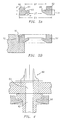
- sealing element 52 is shown in more detail in Figure 3A.
- Element 52 is a substantially flat ring or disc having an outer surface 62 with a first diameter D1, a first thickness T1, a first inner surface 64 with a second diameter D2 smaller than D1.
- element 52 has an inner angular portion 66 with a third diameter D3 smaller than D2 and a second thickness T2 smaller than T1.
- the inner surface 64 includes inner angular portion 66 which desirably has a rounded end 68.
- the sealing or deflection element may have a shape other than a disc, as a square, hexagonal or any desirable non-circular profile.
- Outer surface 62 could be smooth and have substantially the same diameter as the cylindrical recess 56.
- element 52 is provided with outer thread 70 and this can be threaded into the corresponding cylindrical recess 72. This would make it easier to place and replace the element 52 during assembly or servicing.
- Angular portion 66 defines an angle ⁇ with respect to the nozzle conduit as shown in Figure 3A which desirably is between 5° and 30° which insures that the sealing force is angularly directed towards the interface between the nozzle and manifold conduits.
- Figures 5 and 6 show alternate embodiments of sealing elements, with Figure 5 showing a flat, disc-like element 74 which also creates an angular sealing force and achieves the sealing stress distribution shown in distribution curve 76 which has its peak adjacent the conduits, and with Figure 6 showing a flat, disc-like element 78 with a flat body portion 80 and an annular tip 82 upwardly directed relative to body portion 80, which also achieves a sealing stress distribution which has its peak adjacent the conduits as shown in distribution curve 84.
- the deflection element can be made of various materials or material combinations, with the final selection based on particular molding conditions.
- the element is made of a high thermally conductive material, such as high strength steel.
- the element may be made of a material with lower thermal conductivity than the material of the nozzle housing, as titanium or a titanium alloy and the nozzle housing of copper or copper beryllium. In some applications this makes the sealing even more reliable due to the additional force created when the high thermal radial expansion of the nozzle is limited by the lower thermal expansion of the deflection ring which is also surrounded by a cold mold plate.
- the deflection ring could have a core portion made of steel and a skin portion made of low thermal conductivity material (insulator) or only a coating layer of an insulator. Naturally, other options may be used.
- an interference fit is created between the sealing ring and the nozzle shoulder portion.
- An intimate radial fit between the ring and the shoulder will insure that the interference fit is maintained during a broad spectrum of operating conditions, such as temperature and pressure variations.
- This initial interference fit is firstly created in cold conditions and produces a significant angular force component directed towards the interface between the two channels to be sealed. This initial sealing force is strong enough to seal the manifold and the nozzle in the event of a cold start of the molding process that may occur by accident.
- deflection sealing ring of the present invention is responsive to the operating conditions in the mold in such a manner that the sealing force acting angularly towards the passageway to be sealed increases with the increase of the temperature and the injection pressure.
- the specific geometry and tolerances for the sealing ring and the cylindrical recess are not very critical as long as the sealing force is angularly directed towards the passageway between the two channels.
- the present invention responds to the changes in the operation conditions, especially to the temperature gradient.
- the sealing ring may be used within the parameters herein, with the resulting radial sealing force generating the required sealing force in both cold and hot conditions.
- the effect of this force is two-fold, first of all it slightly deforms the nozzle's shoulder upper surface. Second, it generates a sealing stress distribution that reaches its maximum value immediately adjacent to the outer surface of the channels to be sealed, in between the manifold and the nozzle.
- an additional element or elements can be used in conjunction with the sealing element herein in order to, for example, better address heat transfer in the area, such as ceramic rings or titanium rings or other low thermally conductive materials.
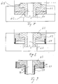
- the present invention discloses the use of thermal insulation means located in this area, such as coatings, sleeves and/or rings as they are shown in Figures 7-9.
- the deflection sealing ring 52 according to this invention will thus sit on top of the insulative ring 53, wherein said ring 53 may in a preferred embodiment have the additional function of locating accurately the nozzle in the mold plate. In this configuration, the sealing ring and the insulative ring do not functionally cooperate.
- a thermal insulative means 55 made again of any known and suitable material, such as any ceramic, titanium and titanium alloys or VespelTM, cooperates with the deflection sealing ring 52. More precisely, insulative sleeve 55 is used as an extension of sealing ring 52 and also, in some instances to locate both the sealing ring 52 and the nozzle in the mold plate.
- a thermal insulative means 57 and 59 can be a coating or a solid sleeve applied to the outside of sealing ring 52 or to the nozzle housing 34 as shown, or can be a separate element, made again of suitable and known materials as discussed above.
- the two sleeves 57 and 59 or two equivalent coating areas can be used together or either one, depending on manufacturing and processing issues. If a coating is used as a thermal insulative means 57 and/or 59, one option is to use a thermal insulative thin film made of ceramics such as alumina, zirconia, titanium oxide or aluminum titanate. In some applications, these coatings could be applied in the inner portion of nozzle conduit 42, more exactly on the melt channel surface.
- a thin film protective layer made of a wear resistant material is applied over the thermal insulative layer.
- good results are achieved by using a TiN thin film or a diamond-like carbon thin film.
- the thermal insulative coating can be applied by spraying appropriate known layers, such as for example coatings including ceramics. Good results are achieved using zirconia oxide sprayed to thickness of no more than 7,6mm (0.300 inches).
- a subsequent protective wear resistive layer might be applied.
- known materials such as nickel, titanium, tungsten carbide or molybdenum can be successfully used.
Landscapes
- Engineering & Computer Science (AREA)
- Manufacturing & Machinery (AREA)
- Mechanical Engineering (AREA)
- Moulds For Moulding Plastics Or The Like (AREA)
- Injection Moulding Of Plastics Or The Like (AREA)
Applications Claiming Priority (2)
| Application Number | Priority Date | Filing Date | Title |
|---|---|---|---|
| US747281 | 1996-11-12 | ||
| US08/747,281 US5896640A (en) | 1996-11-12 | 1996-11-12 | Deflection sealing apparatus and method |
Publications (2)
| Publication Number | Publication Date |
|---|---|
| EP0841141A1 true EP0841141A1 (fr) | 1998-05-13 |
| EP0841141B1 EP0841141B1 (fr) | 1999-07-28 |
Family
ID=25004427
Family Applications (1)
| Application Number | Title | Priority Date | Filing Date |
|---|---|---|---|
| EP97810860A Expired - Lifetime EP0841141B1 (fr) | 1996-11-12 | 1997-11-12 | Appareil et méthode pour réaliser un joint en déflexion |
Country Status (4)
| Country | Link |
|---|---|
| US (1) | US5896640A (fr) |
| EP (1) | EP0841141B1 (fr) |
| JP (1) | JP3048984B2 (fr) |
| DE (1) | DE69700357T2 (fr) |
Cited By (5)
| Publication number | Priority date | Publication date | Assignee | Title |
|---|---|---|---|---|
| WO2001087570A1 (fr) * | 2000-05-19 | 2001-11-22 | Husky Injection Molding Systems Ltd. | Appareil d"etancheite a canaux chauffants ameliore et procede associe |
| WO2005023509A1 (fr) | 2003-09-09 | 2005-03-17 | Mold-Masters Limited | Dispositif assurant une etancheite entre une buse d'injection a canaux chauffants et un collecteur |
| US7189071B2 (en) | 2003-02-12 | 2007-03-13 | Mold-Masters Limited | Telescopic manifold nozzle seal |
| US7194184B2 (en) * | 2003-03-10 | 2007-03-20 | Fiberstars Incorporated | Light pipe with side-light extraction |
| DE10297058B4 (de) * | 2001-07-24 | 2008-07-31 | Husky Injection Molding Systems Ltd., Bolton | Heißkanalsystem in einer Spritzgussmaschine |
Families Citing this family (17)
| Publication number | Priority date | Publication date | Assignee | Title |
|---|---|---|---|---|
| WO1999037461A1 (fr) * | 1998-01-21 | 1999-07-29 | Protool Ag | Manchon mobile distributeur de la matiere plastique fondue permettant de compenser la dilatation thermique entre le canal de carotte chauffe et l'entree du moule |
| US6071184A (en) * | 1998-09-02 | 2000-06-06 | Seh America, Inc. | Fluid deflecting device for use in work piece holder during a semiconductor wafer grinding process |
| US6280175B1 (en) * | 1999-05-12 | 2001-08-28 | Toyo Tire & Rubber Co., Ltd. | Nozzle for injection molding rubber products |
| US6368542B1 (en) * | 2000-06-15 | 2002-04-09 | D-M-E Company | Thermal expansion compensation support |
| CA2311829A1 (fr) * | 2000-06-16 | 2001-12-16 | Jonathon Fischer | Buse d'injection a chaud en equilibre thermique |
| DE60328263D1 (de) * | 2002-02-04 | 2009-08-20 | Mold Masters 2007 Ltd | Thermische abdichtung zwischen verteiler und düse |
| US6890473B2 (en) * | 2002-09-03 | 2005-05-10 | Mold-Masters Limited | Alignment collar for a nozzle |
| US20040258795A1 (en) * | 2003-06-23 | 2004-12-23 | Hans Guenther | Injection molding nozzle with separate nozzle flange |
| US7165958B2 (en) * | 2004-04-23 | 2007-01-23 | Husky Injection Molding Systems Ltd. | Apparatus for adjustable hot runner assembly seals and tip height using active material elements |
| US7381050B2 (en) | 2004-10-20 | 2008-06-03 | Mold-Masters (2007) Limited | Snap on flange for injection molding nozzle |
| US7890896B2 (en) * | 2005-11-18 | 2011-02-15 | Synopsys, Inc. | Method and apparatus for distinguishing combinational designs |
| JP5128147B2 (ja) * | 2007-02-28 | 2013-01-23 | 株式会社尾関ホットランナープラン | 射出成形装置 |
| US7874833B2 (en) * | 2009-05-03 | 2011-01-25 | Mold-Masters (2007) Limited | Injection molding runner apparatus having pressure seal |
| US8865048B2 (en) * | 2012-12-28 | 2014-10-21 | Injectnotech Inc. | Injection molding nozzle with dynamic seal |
| US9272455B2 (en) | 2014-04-30 | 2016-03-01 | Mold-Masters (2007) Limited | Hot runner system sealing arrangement |
| US11225003B2 (en) * | 2019-04-17 | 2022-01-18 | Mold-Masters (2007) Limited | Hot runner system |
| US12151414B2 (en) | 2021-07-22 | 2024-11-26 | Injectnotech Inc. | Injection molding system with dynamic nozzle seal |
Citations (4)
| Publication number | Priority date | Publication date | Assignee | Title |
|---|---|---|---|---|
| US4279588A (en) * | 1980-07-15 | 1981-07-21 | Gellert Jobst U | Hot tip seal |
| US4682945A (en) * | 1984-07-16 | 1987-07-28 | Husky Injection Molding Systems Ltd. | Thermal insulating and expansion assembly for injection molding machine |
| US5429491A (en) * | 1994-06-30 | 1995-07-04 | Gellert; Jobst U. | Injection molding nozzle with removable collar portion |
| EP0677370A1 (fr) * | 1994-04-13 | 1995-10-18 | Caco Pacific Corporation | Système d'entrée d'injection à valve du type dos à dos |
Family Cites Families (12)
| Publication number | Priority date | Publication date | Assignee | Title |
|---|---|---|---|---|
| US4588367A (en) * | 1984-07-16 | 1986-05-13 | Husky Injection Molding Systems Ltd. | Hot runner manifold for injection molding machine |
| CA1252970A (fr) * | 1986-10-23 | 1989-04-25 | Mold-Masters Limited | Manchon double d'alimentation pour machine multicavite a mouler par injection |
| CA1268915A (fr) * | 1989-02-10 | 1990-05-15 | Jobst Ulrich Gellert | Buse de moulage par injection garnie de sondes conductives espacees a sa circonference |
| US5062648A (en) * | 1989-09-26 | 1991-11-05 | Interventional Technologies, Inc. | Seal for rotating torque tube with seal valve |
| DE4028660A1 (de) * | 1990-09-10 | 1992-03-26 | Incoe International Inc Zweign | Heisskanal-verteilersystem |
| US5374182A (en) * | 1992-09-30 | 1994-12-20 | Husky Injection Molding Systems Ltd. | Hot runner manifold bushing |
| US5324191A (en) * | 1992-09-30 | 1994-06-28 | Husky Injection Molding Systems Ltd. | Sealed edge gate |
| FR2706976B1 (fr) * | 1993-06-25 | 1995-10-20 | Solvay | |
| WO1995005276A1 (fr) * | 1993-08-12 | 1995-02-23 | Kona Corporation | Systeme ameliore de moulage par injection a canaux chauffants |
| US5507637A (en) * | 1995-03-02 | 1996-04-16 | Husky Injection Molding Systems Ltd. | Hot runner sliding nozzle |
| FR2733021B1 (fr) * | 1995-04-13 | 1997-06-06 | Joint Francais | Joint et son procede de montage |
| US5820899A (en) * | 1996-12-23 | 1998-10-13 | Mold-Masters Limited | Injection molding nozzle with edge gate inserts and sealing ring |
-
1996
- 1996-11-12 US US08/747,281 patent/US5896640A/en not_active Expired - Fee Related
-
1997
- 1997-11-12 EP EP97810860A patent/EP0841141B1/fr not_active Expired - Lifetime
- 1997-11-12 DE DE69700357T patent/DE69700357T2/de not_active Expired - Fee Related
- 1997-11-12 JP JP9310416A patent/JP3048984B2/ja not_active Expired - Lifetime
Patent Citations (4)
| Publication number | Priority date | Publication date | Assignee | Title |
|---|---|---|---|---|
| US4279588A (en) * | 1980-07-15 | 1981-07-21 | Gellert Jobst U | Hot tip seal |
| US4682945A (en) * | 1984-07-16 | 1987-07-28 | Husky Injection Molding Systems Ltd. | Thermal insulating and expansion assembly for injection molding machine |
| EP0677370A1 (fr) * | 1994-04-13 | 1995-10-18 | Caco Pacific Corporation | Système d'entrée d'injection à valve du type dos à dos |
| US5429491A (en) * | 1994-06-30 | 1995-07-04 | Gellert; Jobst U. | Injection molding nozzle with removable collar portion |
Cited By (6)
| Publication number | Priority date | Publication date | Assignee | Title |
|---|---|---|---|---|
| WO2001087570A1 (fr) * | 2000-05-19 | 2001-11-22 | Husky Injection Molding Systems Ltd. | Appareil d"etancheite a canaux chauffants ameliore et procede associe |
| DE10297058B4 (de) * | 2001-07-24 | 2008-07-31 | Husky Injection Molding Systems Ltd., Bolton | Heißkanalsystem in einer Spritzgussmaschine |
| US7189071B2 (en) | 2003-02-12 | 2007-03-13 | Mold-Masters Limited | Telescopic manifold nozzle seal |
| US7194184B2 (en) * | 2003-03-10 | 2007-03-20 | Fiberstars Incorporated | Light pipe with side-light extraction |
| WO2005023509A1 (fr) | 2003-09-09 | 2005-03-17 | Mold-Masters Limited | Dispositif assurant une etancheite entre une buse d'injection a canaux chauffants et un collecteur |
| EP1663607A4 (fr) * | 2003-09-09 | 2009-09-02 | Mold Masters 2007 Ltd | Dispositif assurant une etancheite entre une buse d'injection a canaux chauffants et un collecteur |
Also Published As
| Publication number | Publication date |
|---|---|
| DE69700357T2 (de) | 2000-01-20 |
| JP3048984B2 (ja) | 2000-06-05 |
| EP0841141B1 (fr) | 1999-07-28 |
| DE69700357D1 (de) | 1999-09-02 |
| US5896640A (en) | 1999-04-27 |
| JPH10156892A (ja) | 1998-06-16 |
Similar Documents
| Publication | Publication Date | Title |
|---|---|---|
| EP0841141B1 (fr) | Appareil et méthode pour réaliser un joint en déflexion | |
| US6164954A (en) | High pressure injection nozzle | |
| US7168941B2 (en) | Thermal seal between manifold and nozzle | |
| US5980237A (en) | Injection molding nozzle | |
| CN1024329C (zh) | 带有弹簧助力注嘴的注射成型系统 | |
| US7549855B2 (en) | Nozzle tip for high melt pressure applications | |
| US7614869B2 (en) | Manifold nozzle connection for an injection molding system | |
| EP0732185B1 (fr) | Dispositif d'injection amélioré-bloc de distribution pour une machine d'injection | |
| EP2174767B1 (fr) | Buse à canaux chauffants à obturateur de moulage par injection | |
| KR100536548B1 (ko) | 개선된 핫 러너 밀봉 장치 및 방법 | |
| EP0405007A2 (fr) | Système de moulage par injection ayant une douille à double alimentation montée dans le canal de distribution | |
| EP0153554A2 (fr) | Dispositif de buse à obturation pour moulage par injection | |
| US20040258793A1 (en) | Removable heater for a hot runner nozzle | |
| US6318990B1 (en) | Injection molding nozzle apparatus | |
| EP1466715B1 (fr) | Buse à canal de chauffé avec étanchification de la matière fondue | |
| US8985997B2 (en) | Valve bushing for an injection molding apparatus | |
| AU2001237184A1 (en) | Improved hot runner sealing apparatus and method | |
| EP1436133B1 (fr) | Joint place entre une buse et un composant moule dans un ensemble a canaux chauffants pour un appareil de moulage par injection | |
| JP2003535728A (ja) | 取り外し自在のシールを備えた射出成形ホットランナーノズル | |
| EP1663607B1 (fr) | Dispositif assurant une etancheite entre une buse d'injection a canaux chauffants et un collecteur | |
| US20040228942A1 (en) | Hot runner nozzle with removable tip and tip retainer | |
| US20040043102A1 (en) | Alignment collar for a nozzle | |
| US7258541B2 (en) | Thermal expansion compensation support | |
| EP0346900A2 (fr) | Système de moulage par injection avec anneau d'isolation insérable | |
| CA1314370C (fr) | Systeme de moulage par injection a insertions refroidies par liquide |
Legal Events
| Date | Code | Title | Description |
|---|---|---|---|
| PUAI | Public reference made under article 153(3) epc to a published international application that has entered the european phase |
Free format text: ORIGINAL CODE: 0009012 |
|
| AK | Designated contracting states |
Kind code of ref document: A1 Designated state(s): BE DE FR GB IT NL |
|
| AX | Request for extension of the european patent |
Free format text: AL;LT;LV;MK;RO;SI |
|
| 17P | Request for examination filed |
Effective date: 19980514 |
|
| GRAG | Despatch of communication of intention to grant |
Free format text: ORIGINAL CODE: EPIDOS AGRA |
|
| 17Q | First examination report despatched |
Effective date: 19980730 |
|
| GRAG | Despatch of communication of intention to grant |
Free format text: ORIGINAL CODE: EPIDOS AGRA |
|
| GRAG | Despatch of communication of intention to grant |
Free format text: ORIGINAL CODE: EPIDOS AGRA |
|
| GRAH | Despatch of communication of intention to grant a patent |
Free format text: ORIGINAL CODE: EPIDOS IGRA |
|
| GRAH | Despatch of communication of intention to grant a patent |
Free format text: ORIGINAL CODE: EPIDOS IGRA |
|
| AKX | Designation fees paid |
Free format text: BE DE FR GB IT NL |
|
| RBV | Designated contracting states (corrected) |
Designated state(s): BE DE FR GB IT NL |
|
| GRAA | (expected) grant |
Free format text: ORIGINAL CODE: 0009210 |
|
| AK | Designated contracting states |
Kind code of ref document: B1 Designated state(s): BE DE FR GB IT NL |
|
| REF | Corresponds to: |
Ref document number: 69700357 Country of ref document: DE Date of ref document: 19990902 |
|
| ITF | It: translation for a ep patent filed | ||
| ET | Fr: translation filed | ||
| PLBE | No opposition filed within time limit |
Free format text: ORIGINAL CODE: 0009261 |
|
| STAA | Information on the status of an ep patent application or granted ep patent |
Free format text: STATUS: NO OPPOSITION FILED WITHIN TIME LIMIT |
|
| 26N | No opposition filed | ||
| PGFP | Annual fee paid to national office [announced via postgrant information from national office to epo] |
Ref country code: FR Payment date: 20011113 Year of fee payment: 5 |
|
| PGFP | Annual fee paid to national office [announced via postgrant information from national office to epo] |
Ref country code: GB Payment date: 20011114 Year of fee payment: 5 |
|
| PGFP | Annual fee paid to national office [announced via postgrant information from national office to epo] |
Ref country code: DE Payment date: 20011126 Year of fee payment: 5 |
|
| PGFP | Annual fee paid to national office [announced via postgrant information from national office to epo] |
Ref country code: NL Payment date: 20011129 Year of fee payment: 5 |
|
| REG | Reference to a national code |
Ref country code: GB Ref legal event code: IF02 |
|
| PGFP | Annual fee paid to national office [announced via postgrant information from national office to epo] |
Ref country code: BE Payment date: 20020124 Year of fee payment: 5 |
|
| PG25 | Lapsed in a contracting state [announced via postgrant information from national office to epo] |
Ref country code: GB Free format text: LAPSE BECAUSE OF NON-PAYMENT OF DUE FEES Effective date: 20021112 |
|
| PG25 | Lapsed in a contracting state [announced via postgrant information from national office to epo] |
Ref country code: BE Free format text: LAPSE BECAUSE OF NON-PAYMENT OF DUE FEES Effective date: 20021130 |
|
| BERE | Be: lapsed |
Owner name: *HUSKY INJECTION MOLDING SYSTEMS LTD Effective date: 20021130 |
|
| PG25 | Lapsed in a contracting state [announced via postgrant information from national office to epo] |
Ref country code: NL Free format text: LAPSE BECAUSE OF NON-PAYMENT OF DUE FEES Effective date: 20030601 |
|
| PG25 | Lapsed in a contracting state [announced via postgrant information from national office to epo] |
Ref country code: DE Free format text: LAPSE BECAUSE OF NON-PAYMENT OF DUE FEES Effective date: 20030603 |
|
| GBPC | Gb: european patent ceased through non-payment of renewal fee | ||
| PG25 | Lapsed in a contracting state [announced via postgrant information from national office to epo] |
Ref country code: FR Free format text: LAPSE BECAUSE OF NON-PAYMENT OF DUE FEES Effective date: 20030731 |
|
| NLV4 | Nl: lapsed or anulled due to non-payment of the annual fee |
Effective date: 20030601 |
|
| REG | Reference to a national code |
Ref country code: FR Ref legal event code: ST |
|
| PG25 | Lapsed in a contracting state [announced via postgrant information from national office to epo] |
Ref country code: IT Free format text: LAPSE BECAUSE OF NON-PAYMENT OF DUE FEES Effective date: 20051112 |