EP0841142A2 - Spritzgussform - Google Patents
Spritzgussform Download PDFInfo
- Publication number
- EP0841142A2 EP0841142A2 EP97890219A EP97890219A EP0841142A2 EP 0841142 A2 EP0841142 A2 EP 0841142A2 EP 97890219 A EP97890219 A EP 97890219A EP 97890219 A EP97890219 A EP 97890219A EP 0841142 A2 EP0841142 A2 EP 0841142A2
- Authority
- EP
- European Patent Office
- Prior art keywords
- nozzle
- injection
- nozzle tip
- injection mold
- mold according
- Prior art date
- Legal status (The legal status is an assumption and is not a legal conclusion. Google has not performed a legal analysis and makes no representation as to the accuracy of the status listed.)
- Granted
Links
Images


Classifications
-
- B—PERFORMING OPERATIONS; TRANSPORTING
- B29—WORKING OF PLASTICS; WORKING OF SUBSTANCES IN A PLASTIC STATE IN GENERAL
- B29C—SHAPING OR JOINING OF PLASTICS; SHAPING OF MATERIAL IN A PLASTIC STATE, NOT OTHERWISE PROVIDED FOR; AFTER-TREATMENT OF THE SHAPED PRODUCTS, e.g. REPAIRING
- B29C45/00—Injection moulding, i.e. forcing the required volume of moulding material through a nozzle into a closed mould; Apparatus therefor
- B29C45/17—Component parts, details or accessories; Auxiliary operations
- B29C45/26—Moulds
- B29C45/27—Sprue channels ; Runner channels or runner nozzles
- B29C45/2756—Cold runner channels
-
- B—PERFORMING OPERATIONS; TRANSPORTING
- B29—WORKING OF PLASTICS; WORKING OF SUBSTANCES IN A PLASTIC STATE IN GENERAL
- B29C—SHAPING OR JOINING OF PLASTICS; SHAPING OF MATERIAL IN A PLASTIC STATE, NOT OTHERWISE PROVIDED FOR; AFTER-TREATMENT OF THE SHAPED PRODUCTS, e.g. REPAIRING
- B29C45/00—Injection moulding, i.e. forcing the required volume of moulding material through a nozzle into a closed mould; Apparatus therefor
- B29C45/17—Component parts, details or accessories; Auxiliary operations
- B29C45/26—Moulds
- B29C45/27—Sprue channels ; Runner channels or runner nozzles
- B29C45/278—Nozzle tips
-
- B—PERFORMING OPERATIONS; TRANSPORTING
- B29—WORKING OF PLASTICS; WORKING OF SUBSTANCES IN A PLASTIC STATE IN GENERAL
- B29C—SHAPING OR JOINING OF PLASTICS; SHAPING OF MATERIAL IN A PLASTIC STATE, NOT OTHERWISE PROVIDED FOR; AFTER-TREATMENT OF THE SHAPED PRODUCTS, e.g. REPAIRING
- B29C45/00—Injection moulding, i.e. forcing the required volume of moulding material through a nozzle into a closed mould; Apparatus therefor
- B29C45/17—Component parts, details or accessories; Auxiliary operations
- B29C45/26—Moulds
- B29C45/27—Sprue channels ; Runner channels or runner nozzles
- B29C2045/2764—Limited contact between nozzle and mould
-
- B—PERFORMING OPERATIONS; TRANSPORTING
- B29—WORKING OF PLASTICS; WORKING OF SUBSTANCES IN A PLASTIC STATE IN GENERAL
- B29C—SHAPING OR JOINING OF PLASTICS; SHAPING OF MATERIAL IN A PLASTIC STATE, NOT OTHERWISE PROVIDED FOR; AFTER-TREATMENT OF THE SHAPED PRODUCTS, e.g. REPAIRING
- B29C45/00—Injection moulding, i.e. forcing the required volume of moulding material through a nozzle into a closed mould; Apparatus therefor
- B29C45/17—Component parts, details or accessories; Auxiliary operations
- B29C45/26—Moulds
- B29C45/27—Sprue channels ; Runner channels or runner nozzles
- B29C2045/2796—Axially movable nozzles or nozzle tips
-
- B—PERFORMING OPERATIONS; TRANSPORTING
- B29—WORKING OF PLASTICS; WORKING OF SUBSTANCES IN A PLASTIC STATE IN GENERAL
- B29K—INDEXING SCHEME ASSOCIATED WITH SUBCLASSES B29B, B29C OR B29D, RELATING TO MOULDING MATERIALS OR TO MATERIALS FOR MOULDS, REINFORCEMENTS, FILLERS OR PREFORMED PARTS, e.g. INSERTS
- B29K2021/00—Use of unspecified rubbers as moulding material
- B29K2021/006—Thermosetting elastomers
Definitions
- the invention relates to an injection mold according to the preamble of patent claim 1.
- Thermosetting materials in the sense of the invention are essentially plastics that solidify at higher temperatures, or vulcanizing, elastomeric materials, such as silicone or rubber. Such plastics are injected through a spray nozzle into a mold cavity during processing at low temperature, and vulcanize there under the influence of heat to the desired injection molded part. This mold nest is in a hot mold plate. Since the spray nozzle extends into the hot mold plate, measures must be taken to keep the temperature of the spray nozzle low. Otherwise the material would already vulcanize in the spray nozzle and block it.
- the spray nozzle ranges from a cold mold plate to an insulating plate and a heating plate to the hot mold plate. It is arranged in a bore and is generally insulated from the hot molding plate. The most effective way to remove such insulation is through an air gap.
- a mold for injection molding is known in which a pressure piece is inserted between the spray nozzle and the mold plate.
- the sealing between the spray nozzle and the pressure piece and between the pressure piece and the molding plate takes place in each case either by the abutment of two end faces against one another or by a close fit between two peripheral faces. In this way it is particularly prevented that the gap between the spray nozzle and the pressure piece or between the pressure piece and the molding plate cannot fill with the material.
- the heat transfer between the mold plate and the nozzle can be kept relatively low in this known arrangement by means of an appropriate structural design and by the choice of suitable materials.
- it is disadvantageous that the sealing between the components requires machining with the highest accuracy and close tolerances.
- the temperature differences between the individual components must not be too large to avoid different thermal expansions. Therefore, the solution disclosed in this document is very complex and involves a complicated production.
- an injection mold is known from AT-B 401 253, in which an antechamber is provided, into which the injection nozzle opens.
- the antechamber is intended to fill with casting material during injection and thereby form an insulating layer.
- a disadvantage of this device is the danger that the material in the antechamber vulcanized due to the heat transfer from the mold plate and that an already vulcanized material is entrained into the mold cavity during the next casting, which leads to a reduction in the quality of the injection molded part.
- thermoplastic materials are known from EP-A 344 381, in which an intermediate piece is provided to improve the seal.
- an intermediate piece is provided to improve the seal.
- such a nozzle cannot be used for thermosetting materials.
- the object of the present invention is to avoid the above disadvantages and to provide an injection mold which is simple to manufacture and which enables safe operation under various operating conditions.
- the heat transfer by heat conduction is reduced on the one hand and a secure seal can be achieved on the other hand by the increased surface pressure. It is particularly advantageous that it is no longer necessary to use special materials such as titanium or the like for the nozzle tip.
- the seat surface is spherical in the area of the molding plate. Especially in interaction With an equally spherical nozzle tip, the radius of curvature of which is different from that of the seat surface, favorable results can be achieved.
- the nozzle tip can be designed as a wear part that is replaced at the end of its service life.
- the contact pressure of the nozzle tip on the seat can be achieved by various measures.
- a constant contact pressure can be achieved by means of a seal or appropriate springs.
- the nozzle tip is designed to be movable with respect to the nozzle, as a result of which the nozzle tip can also be easily replaced.
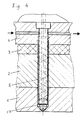
- FIGS. 5 and 6 show details of further embodiment variants of the invention in a longitudinal section.
- a shaped plate 1, a heating plate 2, a temperature protection plate 3 and a cooling plate 4 are arranged one above the other.
- a nozzle 5 is arranged in a bore extending through these components; a mold cavity, which is located after the mold plate 1, is indicated schematically by 6.
- the mold plate 1 has a short injection channel 7, which opens into the mold cavity 6 via an injection opening 8.
- the nozzle 5 is provided in a manner known per se with cooling channels 9 which extend in the form of a two-start screw on the circumference of the nozzle 5.
- a channel 10 for a cooling medium is provided in the cooling plate 4, which channel 10 is connected to the cooling channels 9 of the nozzle 5.
- the nozzle 5 is sealed off from a feed unit 11 (not shown in more detail) by means of a seal 12 which is made, for example, of PTFE.
- This seal 12 has sufficient elasticity to always be for one to ensure appropriate contact pressure of the nozzle tip 15 on the mold plate 1.
- the seal 12 is in all operating conditions at a well-defined temperature, namely that of the cooling plate, which is also the temperature of the nozzle in this area.
- the material of the seal 12 can be optimally designed for this temperature.
- the elasticity of the seal 12 is sufficiently large to be able to compensate for any different thermal expansion of the nozzle 5 compared to the components 1, 2, 3 and 4 in which it is installed.
- FIG. 2 differs from that of FIG. 1 in that in the area of the feed opening 13 for the material, the nozzle 5 has a conically enlarged inlet section 14. In this way, the pressure of the material to be injected is converted into a downward axial force which presses the nozzle 5 against the mold plate 1.
- FIG. 3 is essentially analogous to that of FIG. 2 in its mode of operation. What is different, however, is that the nozzle tip 15a is designed as a separate component that is movable in the axial direction relative to the actual nozzle 5.
- the nozzle tip 15a in turn has a conical inlet opening 16 which in turn converts the pressure of the material to be injected into an axial force which acts on the nozzle tip 15a.
- the advantage of this embodiment variant lies in the easy interchangeability of the nozzle tip 15a.
- a plate spring 17 is provided, which biases the nozzle 5 downwards in order to generate the force which is necessary to ensure a reliable sealing of the nozzle 5 with respect to the mold plate 1.
- FIG. 5 shows the area of the nozzle tip in detail for better understanding. It can be seen that at the end of the injection channel 7, a seat 18 is formed in the mold plate 1, which is spherical around the injection channel 7, with a radius of curvature R. A conical section 19 follows this seat 18.
- the nozzle tip 15 is also spherical, with a radius of curvature r that is smaller than the radius of curvature R of the seat surface 18. In this way, there is contact between the nozzle tip 15 and seat surface 18 along a circular line. A gap 20 in the remaining sections is used for thermal insulation.
- a centering collar 21 is also formed on the nozzle 5, which is free to minimize the heat transfer from the mold plate 1.
- FIG. 6 shows an embodiment variant in which the nozzle tip 15b is designed as an exchangeable wear part.
- the present invention enables a robust and wear-resistant construction of an injection mold with low demands on the manufacturing tolerances.
- the injection point which lies directly in the mold plate and is not part of the nozzle, can be kept extremely small, which enables injection on the thinnest wall thicknesses.
- the simple structure of the invention enables a closed arrangement of the nozzle and the hot mold plate, but without being in direct contact with the mold cavity and without the connection of an additional sleeve made of special materials.
Landscapes
- Engineering & Computer Science (AREA)
- Manufacturing & Machinery (AREA)
- Mechanical Engineering (AREA)
- Moulds For Moulding Plastics Or The Like (AREA)
- Diaphragms For Electromechanical Transducers (AREA)
- Injection Moulding Of Plastics Or The Like (AREA)
- Pens And Brushes (AREA)
- Non-Silver Salt Photosensitive Materials And Non-Silver Salt Photography (AREA)
- Pharmaceuticals Containing Other Organic And Inorganic Compounds (AREA)
- Surgical Instruments (AREA)
Abstract
Description
- Die Erfindung betrifft eine Spritzgußform gemäß dem Oberbegriff von Patentanspruch 1.
- Wärmehärtbare Materialien im Sinne der Erfindung sind im wesentlichen Kunststoffe, die sich bei höheren Temperaturen verfestigen, oder vulkanisierende, elastomere Materialien, wie etwa Silikone oder Kautschuk. Solche Kunststoffe werden bei der Verarbeitung bei niedriger Temperatur über eine Spritzdüse in ein Formnest gespritzt, und vulkanisieren dort unter Wärmeeinfluß zum gewünschten Spritzgußteil aus. Dieses Formnest befindet sich in einer heißen Formplatte. Da sich die Spritzdüse bis in die heiße Formplatte hinein erstreckt, müssen Maßnahmen getroffen werden, um die Temperatur der Spritzdüse niedrig zu halten. Ansonsten würde das Material bereits in der Spritzdüse ausvulkanisieren und diese blockieren. Die Spritzdüse reicht von einer kalten Formplatte über eine Isolierplatte und eine Heizplatte bis zur heißen Formplatte. Sie ist in einer Bohrung angeordnet und allgemein gegenüber der heißen Formplatte isoliert. Am wirksamsten ist eine solche Isolierung durch einen Luftspalt zu lösen.
- Im Bereich der Düsenspitze jedoch läßt sich eine mittelbare oder unmittelbare Berührung zwischen Düse und heißer Formplatte naturgemäß nicht umgehen. Durch diese Berührung wird zwangsläufig ein Wärmeübergang hervorgerufen, was sich insbesonders deshalb als ungünstig herausstellt, da eine Kühlung der Düse durch ein Kühlmittel in diesem Bereich nicht zufriedenstellend möglich ist.
- Aus der DE-A 31 43 748 ist eine Form zum Spritzgießen bekannt, bei der zwischen der Spritzdüse und der Formplatte ein Druckstück eingefügt ist. Die Abdichtung zwischen Spritzdüse und Druckstück sowie zwischen Druckstück und Formplatte erfolgt dabei jeweils entweder durch das Anliegen zweier Stirnflächen aneinander oder durch eine enge Passung zweier Umfangsflächen. Auf diese Weise wird insbesonders verhindert, daß sich der Spalt zwischen Spritzdüse und Druckstück bzw. zwischen Druckstück und Formplatte nicht mit dem Material füllen kann. Durch eine entsprechende konstruktive Gestaltung und durch die Wahl geeigneter Materialien kann der Wärmeübergang zwischen Formplatte und Düse bei dieser bekannten Anordnung relativ gering gehalten werden. Nachteilig ist jedoch, daß die Abdichtung zwischen den Bauteilen eine Bearbeitung mit höchster Genauigkeit und engen Toleranzen erfordert. Weiters dürfen die Temperaturdifferenzen zwischen den einzelnen Bauteilen nicht zu groß werden, um unterschiedliche Wärmedehnungen zu vermeiden. Daher ist die in dieser Druckschrift offenbarte Lösung sehr aufwendig und mit einer komplizierten Fertigung verbunden.
- Weiters ist aus der AT-B 401 253 eine Spritzgußform bekannt, bei der eine Vorkammer vorgesehen ist, in die die Einspritzdüse mündet. Die Vorkammer ist dazu vorgesehen, sich beim Einspritzen mit Gußmaterial zu füllen und dadurch eine Isolierschicht auszubilden. Nachteilig bei dieser Vorrichtung ist die Gefahr, daß das Material in der Vorkammer aufgrund des Wärmeüberganges von der Formplatte her ausvulkanisiert und daß beim nächstfolgenden Guß ein bereits ausvulkanisiertes Material in das Formnest mitgerissen wird, was zu einer Qualitätsminderung des Spritzgußteiles führt.
- Eine weitere Lösung ist beispielsweise in der EP-B 0 162 037 offenbart, bei der auf die Düsenspitze eine schmale, dünnwandige Kanüle aufgesetzt ist. Dies stellt jedoch eine sehr filigrane, störanfällige Konstruktion dar, die hohem Verschleiß unterworfen ist. Die zylindrische Abdichtung der Düsenspitze in der Formplatte ist ebenfalls sehr problematisch und erfordert engste Fertigungstoleranzen. Die Kanülenspitze liegt bündig an der Eintrittsöffnung des Formnestes an.
- Ferner ist aus der EP-A 344 381 eine Einspritzdüse für thermoplastische Kunststoffe bekannt, bei der ein Zwischenstück zur Verbesserung der Abdichtung vorgesehen ist. Eine solche Düse ist für warmaushärtende Materialien jedoch nicht verwendbar.
- Aufgabe der vorliegenden Erfindung ist es, die obigen Nachteile zu vermeiden und eine Spritzgußform zu schaffen, die einfach herstellbar ist und die einen sicheren Betrieb bei verschiedenen Einsatzbedingungen ermöglicht.
- Erfindungsgemäß wird diese Aufgabe durch die Merkmale des kennzeichnenden Teils von Patentanspruch 1 gelöst.
- Durch den Wegfall von Zwischenbauteilen zwischen der Düse und der Formplatte kann die Anzahl der Bauteile verringert werden und es wird die Zuverlässigkeit erhöht.
- Durch die Reduzierung einer Auflagefläche zwischen Düsenspitze und Formplatte auf eine Linie wird einerseits die Wärmeübertragung durch Wärmeleitung verringert und andererseits kann durch die erhöhte Flächenpressung eine sichere Abdichtung erreicht werden. Besonders vorteilhaft ist, daß es nicht mehr erforderlich ist, für die Düsenspitze Sondermaterialien, wie etwa Titan od. dgl., zu verwenden.
- In einer vorteilhaften Ausführungsvariante der vorliegenden Erfindung ist vorgesehen, daß die Sitzfläche im Bereich der Formplatte sphärisch ausgebildet ist. Besonders im Zusammenwirken mit einer ebenfalls sphärisch ausgebildeten Düsenspitze, deren Krümmungsradius jedoch unterschiedlich zu der der Sitzfläche ist, können günstige Ergebnisse erzielt werden.
- In Abhängigkeit von dem zu verarbeitenden Material und von der zu erwartenden Standzeit kann die Düsenspitze als Verschleißteil ausgebildet sein, das am Ende seiner Lebensdauer ausgewechselt wird.
- Der Anpreßdruck der Düsenspitze auf die Sitzfläche kann durch verschiedene Maßnahmen erreicht werden. Durch eine Dichtung oder durch entsprechende Federn kann ein gleichbleibender Anpreßdruck erzielt werden. Besonders günstig ist es jedoch, diesen gleichbleibenden Anpreßdruck während des Einspritzvorganges durch eine zusätzliche Druckkraft zu unterstützen, die durch den Einspritzdruck des Materials selbst hervorgerufen wird. Auf diese Weise wird erreicht, daß bei hohen Einspritzdrücken, bei denen an die Abdichtung besonders hohe Anforderungen gestellt werden, eine hohe Auflagekraft der Düsenspitze auf der Sitzfläche erzielt wird.
- In einer besonders bevorzugten Ausführungsvariante der vorliegenden Erfindung ist die Düsenspitze beweglich im Bezug auf die Düse ausgebildet, wodurch auch eine leichte Austauschbarkeit der Düsenspitze erreicht wird.
- In der Folge wird die Erfindung anhand der in den Figuren dargestellten Ausführungsvarianten näher erläutert. Es zeigen die Fig. 1, 2, 3 und 4 verschiedene Ausführungsvarianten der Erfindung jeweils in einem Längsschnitt, die Fig. 5 und 6 Details von weiteren Ausführungsvarianten der Erfindung im Längsschnitt.
- Allen Ausführungsvarianten ist gemeinsam, daß eine Formplatte 1, eine Heizplatte 2, eine Temperaturschutzplatte 3 und eine Kühlplatte 4 übereinander angeordnet sind. In einer sich durch diese Bauteile erstreckenden Bohrung ist eine Düse 5 angeordnet, ein Formnest, das sich im Anschluß an die Formplatte 1 befindet, ist mit 6 schematisch angedeutet. Die Formplatte 1 besitzt einen kurzen Einspritzkanal 7, der über eine Einspritzöffnung 8 in das Formnest 6 mündet. Die Düse 5 ist in an sich bekannter Weise mit Kühlkanälen 9 versehen, die sich in Form einer zweigängigen Schnecke am Umfang der Düse 5 erstrecken. In der Kühlplatte 4 ist ein Kanal 10 für ein Kühlmedium vorgesehen, welcher Kanal 10 mit den Kühlkanälen 9 der Düse 5 in Verbindung steht.
- Bei der Ausführungsvariante von Fig. 1 erfolgt die Abdichtung der Düse 5 gegenüber einer nicht näher dargestellten Zufuhreinheit 11 über eine Dichtung 12, die beispielsweise aus PTFE hergestellt ist. Diese Dichtung 12 besitzt eine ausreichende Elastizität, um stets für einen passenden Anpreßdruck der Düsenspitze 15 an die Formplatte 1 zu sorgen. Die Dichtung 12 befindet sich dabei in allen Betriebsbedingungen auf einer wohl definierten Temperatur, nämlich der, der Kühlplatte, die gleichzeitig die Temperatur der Düse in diesem Bereich ist. Das Material der Dichtung 12 kann dabei in optimaler Weise auf diese Temperatur ausgelegt werden. Bei dieser Ausführungsvariante ist zu beachten, daß die Elastizität der Dichtung 12 ausreichend groß ist, um eine etwaige unterschiedliche Temperaturdehnung der Düse 5 gegenüber den Bauteilen 1, 2, 3 und 4, in denen sie eingebaut ist, ausgleichen zu können.
- Die Ausführungsvariante der Fig. 2 unterscheidet sich gegenüber der von Fig. 1 dadurch, daß im Bereich der Zufuhröffnung 13 für das Material die Düse 5 einen konisch erweiterten Einlaßabschnitt 14 aufweist. Auf diese Weise wird der Druck des einzuspritzenden Materials in eine nach unten gerichtete Axialkraft umgesetzt, die die Düse 5 an die Formplatte 1 anpreßt.
- Die Ausführungsvariante der Fig. 3 ist in ihrer Wirkungsweise im wesentlichen analog zu der von Fig. 2. Unterschiedlich ist jedoch, daß die Düsenspitze 15a als eigener Bauteil ausgeführt ist, der gegenüber der eigentlichen Düse 5 in Axialrichtung beweglich ist. Die Düsenspitze 15a besitzt ihrerseits eine konische Einlaßöffnung 16, die wiederum den Druck des einzuspritzenden Materials in eine Axialkraft umsetzt, die auf die Düsenspitze 15a wirkt. Der Vorteil dieser Ausführungsvariante liegt in der leichten Austauschbarkeit der Düsenspitze 15a.
- Bei der Ausführungsvariante von Fig. 4 ist eine Tellerfeder 17 vorgesehen, die die Düse 5 nach unten vorspannt, um die Kraft zu erzeugen, die notwendig ist, um eine sichere Abdichtung der Düse 5 gegenüber der Formplatte 1 zu gewährleisten.
- In der Fig. 5 ist der Bereich der Düsenspitze zum besseren Verständnis detailliert dargestellt. Es ist ersichtlich, daß am Ende des Einspritzkanals 7 eine Sitzfläche 18 in der Formplatte 1 ausgebildet ist, die rund um den Einspritzkanal 7 sphärisch ausgebildet ist, mit einem Krümmungsradius R. Anschließend an diese Sitzfläche 18 folgt ein konischer Abschnitt 19. Die Düsenspitze 15 ist ebenfalls sphärisch ausgebildet, und zwar mit einem Krümmungsradius r, der kleiner ist, als der Krümmungsradius R der Sitzfläche 18. Auf diese Weise erfolgt eine Berührung zwischen Düsenspitze 15 und Sitzfläche 18 entlang einer Kreislinie. Ein Spalt 20 in den übrigen Abschnitten dient der thermischen Isolierung. An der Düse 5 ist weiters ein Zentrierungsbund 21 angeformt, der freigestellt ist, um den Wärmeübergang von der Formplatte 1 her zu minimieren.
- In der Fig. 6 ist eine Ausführungsvariante dargestellt, bei der die Düsenspitze 15b als austauschbarer Verschleißteil ausgebildet ist.
- Die vorliegende Erfindung ermöglicht eine robuste und verschleißfeste Konstruktion einer Spritzgußform, mit geringen Ansprüchen an die Fertigungstoleranzen. Insbesonders kann der Anspritzpunkt, der direkt in der Formplatte liegt, und kein Teil der Düse ist, extrem klein gehalten werden, was eine Anspritzung an dünnsten Wandstärken ermöglicht.
- Der einfache Aufbau der Erfindung ermöglicht eine geschlossene Anordnung der Düse und der heißen Formplatte, ohne jedoch in direktem Kontakt mit dem Formnest zu stehen und ohne die Verbindung einer zusätzlichen Büchse aus Sonderwerkstoffen.
Claims (9)
- Spritzgußform für plastische wärmehärtbare Materialien, mit einer Formplatte (1), die einen Einspritzkanal (7) aufweist, der in eine Einspritzöffnung (8) mündet, und mit einer thermisch gegenüber der Formplatte (1) isolierten Einspritzdüse (5), die sich zumindest teilweise in einer Bohrung in der Formplatte (1) erstreckt, die im wesentlichen konzentrisch zum Einspritzkanal verläuft, wobei die Einspritzdüse (5) eine im wesentlichen konische Düsenspitze (15, 15a, 15b) aufweist, dadurch gekennzeichnet, daß im Bereich der Mündung des Einspritzkanals (7) in die Bohrung eine Sitzfläche (18) vorgesehen ist, auf der die Düsenspitze (15, 15a, 15b) mit Druck in Axialrichtung der Düse aufliegt, wobei die Berührung zwischen der Düsenspitze (15, 15a, 15b) und der Sitzfläche (18) entlang einer Linie erfolgt.
- Spritzgußform nach Anspruch 1, dadurch gekennzeichnet, daß die Sitzfläche (18) im wesentlichen sphärisch ausgebildet ist.
- Spritzgußform nach Anspruch 2, dadurch gekennzeichnet, daß die Düsenspitze sphärisch ausgebildet ist, wobei die Krümmungen (R, r) von Sitzfläche (18) bzw. Düsenspitze (15, 15a, 15b) unterschiedlich zueinander sind.
- Spritzgußform nach einem der Ansprüche 1 bis 3, dadurch gekennzeichnet, daß die Düsenspitze (15b) als Verschleißteil ausgebildet ist.
- Spritzgußform nach einem der Ansprüche 1 bis 4, dadurch gekennzeichnet, daß die Düse (5) mit Kühlkanälen (9) ausgeführt ist.
- Spritzgußform nach einem der Ansprüche 1 bis 5, dadurch gekennzeichnet, daß im Bereich einer Zufuhröffnung der Düse (5) eine Dichtung (12) vorgesehen ist, die dazu ausgebildet ist, im zusammengebauten Zustand einen Druck in Axialrichtung auf die Düse (5) auszuüben.
- Spritzgußform nach einem der Ansprüche 1 bis 6, dadurch gekennzeichnet, daß im Bereich der Düse (5) eine Druckaufnahmefläche (14, 16) vorgesehen ist, die dazu ausgebildet ist, durch den Druck des Materials eine in Axialrichtung wirkende Kraft auf die Düsenspitze (15, 15a, 15b) zu erzeugen.
- Spritzgußform nach einem der Ansprüche 1 bis 7, dadurch gekennzeichnet, daß Federn (17, 27) vorgesehen sind, um die Düsenspitze (15, 15a, 15b) in Axialrichtung vorzuspannen.
- Spritzgußform nach einem der Ansprüche 1 bis 8, dadurch gekennzeichnet, daß die Düsenspitze (15a) in Axialrichtung beweglich ausgeführt ist.
Applications Claiming Priority (3)
| Application Number | Priority Date | Filing Date | Title |
|---|---|---|---|
| AT193996 | 1996-11-06 | ||
| AT0193996A ATA193996A (de) | 1996-11-06 | 1996-11-06 | Spritzgussform |
| AT1939/96 | 1996-11-06 |
Publications (3)
| Publication Number | Publication Date |
|---|---|
| EP0841142A2 true EP0841142A2 (de) | 1998-05-13 |
| EP0841142A3 EP0841142A3 (de) | 1999-06-16 |
| EP0841142B1 EP0841142B1 (de) | 2000-03-01 |
Family
ID=3524303
Family Applications (1)
| Application Number | Title | Priority Date | Filing Date |
|---|---|---|---|
| EP97890219A Expired - Lifetime EP0841142B1 (de) | 1996-11-06 | 1997-11-04 | Spritzgussform |
Country Status (7)
| Country | Link |
|---|---|
| EP (1) | EP0841142B1 (de) |
| AT (2) | ATA193996A (de) |
| DE (1) | DE59701165D1 (de) |
| DK (1) | DK0841142T3 (de) |
| ES (1) | ES2144838T3 (de) |
| GR (1) | GR3033377T3 (de) |
| PT (1) | PT841142E (de) |
Cited By (8)
| Publication number | Priority date | Publication date | Assignee | Title |
|---|---|---|---|---|
| EP0995573A1 (de) * | 1998-10-21 | 2000-04-26 | Bruno Meroni | System Spritzgiessdüse/Form zum Spritzgiessen von Polymeren, Silikonen oder wärmehärtbarem Material |
| EP1029647A1 (de) | 1999-02-18 | 2000-08-23 | Elast Kunststoffverarbeitungs-GmbH & Co. KEG | Einspritzdüse |
| WO2001087570A1 (en) * | 2000-05-19 | 2001-11-22 | Husky Injection Molding Systems Ltd. | Improved hot runner sealing apparatus and method |
| EP1384560A1 (de) * | 2002-07-26 | 2004-01-28 | Bruno Meroni | Form zum Spritzgiessen von Polymeren, Silikonen oder wärmehärtbaren Materialien mit einer selbstreinigenden Düse und Düse für diese Form |
| EP1813411A3 (de) * | 2006-01-31 | 2007-08-08 | Incoe International, Inc. | Hochbelastbare Dichtungen für Spritzgiessanlagen |
| US7614869B2 (en) | 2007-05-08 | 2009-11-10 | Mold-Masters (2007) Limited | Manifold nozzle connection for an injection molding system |
| DE102014210332A1 (de) * | 2014-06-02 | 2015-12-03 | AWETIS Engineering + Manufacturing GmbH | Einspritzdüse zum Einbringen von Spritzgut in eine Spritzgußform |
| CN113853298A (zh) * | 2019-04-11 | 2021-12-28 | 康宁公司 | 使用cte不匹配改进的边缘强度 |
Families Citing this family (2)
| Publication number | Priority date | Publication date | Assignee | Title |
|---|---|---|---|---|
| US7407379B2 (en) | 2004-10-19 | 2008-08-05 | Mold-Masters (2007) Limited | Injection molding nozzle |
| US7845936B2 (en) | 2009-01-21 | 2010-12-07 | Mold-Masters (2007) Limited | Sealing arrangement for an edge gated nozzle in an injection molding system |
Family Cites Families (7)
| Publication number | Priority date | Publication date | Assignee | Title |
|---|---|---|---|---|
| US2814831A (en) * | 1955-12-27 | 1957-12-03 | Dow Chemical Co | Injection molding apparatus |
| US3677682A (en) * | 1970-03-09 | 1972-07-18 | Ladislao Wladyslaw Putkowski | Hot runner system |
| EP0070925A1 (de) * | 1981-06-29 | 1983-02-09 | Eurotool B.V. | Düse für eine Spritzgiessform |
| JP2545210B2 (ja) * | 1986-04-02 | 1996-10-16 | エヌオーケー株式会社 | 射出成型装置 |
| US5849344A (en) * | 1994-09-28 | 1998-12-15 | Meiho Co., Ltd. | Injection molding apparatus |
| AT401253B (de) * | 1994-11-07 | 1996-07-25 | Rico Elastomere Projecting Gmb | Spritzgussform |
| WO1998012038A1 (de) * | 1996-09-18 | 1998-03-26 | Hefner Gmbh Elastomere Verarbeitung | Spritzgussform für aushärtbare oder vulkanisierende, elastomere materialien |
-
1996
- 1996-11-06 AT AT0193996A patent/ATA193996A/de unknown
-
1997
- 1997-11-04 DE DE59701165T patent/DE59701165D1/de not_active Expired - Lifetime
- 1997-11-04 EP EP97890219A patent/EP0841142B1/de not_active Expired - Lifetime
- 1997-11-04 AT AT97890219T patent/ATE189998T1/de not_active Application Discontinuation
- 1997-11-04 DK DK97890219T patent/DK0841142T3/da active
- 1997-11-04 PT PT97890219T patent/PT841142E/pt unknown
- 1997-11-04 ES ES97890219T patent/ES2144838T3/es not_active Expired - Lifetime
-
2000
- 2000-05-05 GR GR20000401062T patent/GR3033377T3/el not_active IP Right Cessation
Cited By (11)
| Publication number | Priority date | Publication date | Assignee | Title |
|---|---|---|---|---|
| EP0995573A1 (de) * | 1998-10-21 | 2000-04-26 | Bruno Meroni | System Spritzgiessdüse/Form zum Spritzgiessen von Polymeren, Silikonen oder wärmehärtbarem Material |
| EP1029647A1 (de) | 1999-02-18 | 2000-08-23 | Elast Kunststoffverarbeitungs-GmbH & Co. KEG | Einspritzdüse |
| WO2001087570A1 (en) * | 2000-05-19 | 2001-11-22 | Husky Injection Molding Systems Ltd. | Improved hot runner sealing apparatus and method |
| AU2001237184B2 (en) * | 2000-05-19 | 2004-05-06 | Husky Injection Molding Systems Ltd. | Improved hot runner sealing apparatus and method |
| AU2001237184C1 (en) * | 2000-05-19 | 2005-03-03 | Husky Injection Molding Systems Ltd. | Improved hot runner sealing apparatus and method |
| EP1384560A1 (de) * | 2002-07-26 | 2004-01-28 | Bruno Meroni | Form zum Spritzgiessen von Polymeren, Silikonen oder wärmehärtbaren Materialien mit einer selbstreinigenden Düse und Düse für diese Form |
| EP1813411A3 (de) * | 2006-01-31 | 2007-08-08 | Incoe International, Inc. | Hochbelastbare Dichtungen für Spritzgiessanlagen |
| US7614869B2 (en) | 2007-05-08 | 2009-11-10 | Mold-Masters (2007) Limited | Manifold nozzle connection for an injection molding system |
| DE102014210332A1 (de) * | 2014-06-02 | 2015-12-03 | AWETIS Engineering + Manufacturing GmbH | Einspritzdüse zum Einbringen von Spritzgut in eine Spritzgußform |
| CN113853298A (zh) * | 2019-04-11 | 2021-12-28 | 康宁公司 | 使用cte不匹配改进的边缘强度 |
| CN113853298B (zh) * | 2019-04-11 | 2023-08-01 | 康宁公司 | 使用cte不匹配改进的边缘强度 |
Also Published As
| Publication number | Publication date |
|---|---|
| EP0841142B1 (de) | 2000-03-01 |
| ATA193996A (de) | 2000-09-15 |
| ATE189998T1 (de) | 2000-03-15 |
| EP0841142A3 (de) | 1999-06-16 |
| PT841142E (pt) | 2000-08-31 |
| DK0841142T3 (da) | 2000-06-26 |
| DE59701165D1 (de) | 2000-04-06 |
| GR3033377T3 (en) | 2000-09-29 |
| ES2144838T3 (es) | 2000-06-16 |
Similar Documents
| Publication | Publication Date | Title |
|---|---|---|
| DE2709609C2 (de) | Ventilgesteuertes Einlaßteil für Spritzgußwerkzeuge | |
| DE60316444T2 (de) | Ventilnadelführungs- und -ausrichtungssystem für einen heisskanal in einer spritzgiessvorrichtung | |
| DE60115223T2 (de) | Verbessertes heisskanal-verschlussventil kolbenaggregat | |
| DE69709445T2 (de) | Formvorrichtung für optische Platten | |
| DE69524797T2 (de) | Abdichtungsbüchse für Ventil im Spritzgiessen mit dünnem Kragenteil | |
| DE19652047B4 (de) | Heißkanaldüse mit einem Düsenvorderteil aus einer Karbidlegierung | |
| DE68924706T2 (de) | Spritzgiesssystem mit einer Buchse mit doppelter Zufuhr, montiert im Verteilerkanal. | |
| DE20100840U1 (de) | Heißkanaldüse | |
| DE19521733B4 (de) | Einteiliger Druckgußeinsatz mit einer mit radialen Rippen versehenen Kühlkammer | |
| EP0841142A2 (de) | Spritzgussform | |
| DE3833220C2 (de) | Nadelverschlußdüse in einem Spritzgießwerkzeug zur Verarbeitung thermoplastischer Kunststoffe | |
| DE20118609U1 (de) | Einspritzdüse für Kautschuk, Gummi und Polysiloxane | |
| DE2539785C3 (de) | Heißkanalspritzdüse | |
| DE202008007918U1 (de) | Spritzgießdüse für ein Spritzgießwerkzeug | |
| EP2026946B1 (de) | Heisskanaldüse zur anordnung in einem spritzgiesswerkzeug | |
| DE3143748C2 (de) | Form zum Spritzgießen oder Preßspritzen von Kautschuk oder anderen plastischen, wärmehärtbaren Werkstoffen | |
| EP0932488B1 (de) | Spritzgussform für aushärtbare oder vulkanisierende, elastomere materialien | |
| DE202007017136U1 (de) | Verschlussnadel für eine Nadelverschlussdüse | |
| DE19618960B4 (de) | Spritzgießvorrichtung mit verschiebbarer Düse zur Montage von Seitenangussdichtungen | |
| EP1029647B1 (de) | Einspritzdüse | |
| DE3211342A1 (de) | Kunststoffspritzpresse mit einer zufuehrvorrichtung zum zufuehren einer thermoplastischen masse | |
| DE202007001789U1 (de) | Spritzgießdüse | |
| DE202007015873U1 (de) | Spritzgießdüse | |
| EP2069124B1 (de) | Übergabeelement, insbesondere für eine dekompressions-angussbuchse oder eine dekompressions-maschinendüse | |
| EP4241958A1 (de) | Einsatz für eine spritzgiessdüse und spritzgiessdüse mit einem solchen einsatz |
Legal Events
| Date | Code | Title | Description |
|---|---|---|---|
| PUAI | Public reference made under article 153(3) epc to a published international application that has entered the european phase |
Free format text: ORIGINAL CODE: 0009012 |
|
| AK | Designated contracting states |
Kind code of ref document: A2 Designated state(s): AT BE CH DE DK ES FI FR GB GR IE IT LI LU MC NL PT SE |
|
| AX | Request for extension of the european patent |
Free format text: AL;LT;LV;MK;RO;SI |
|
| PUAL | Search report despatched |
Free format text: ORIGINAL CODE: 0009013 |
|
| AK | Designated contracting states |
Kind code of ref document: A3 Designated state(s): AT BE CH DE DK ES FI FR GB GR IE IT LI LU MC NL PT SE |
|
| AX | Request for extension of the european patent |
Free format text: AL;LT;LV;MK;RO;SI |
|
| 17P | Request for examination filed |
Effective date: 19990521 |
|
| 17Q | First examination report despatched |
Effective date: 19990629 |
|
| GRAG | Despatch of communication of intention to grant |
Free format text: ORIGINAL CODE: EPIDOS AGRA |
|
| GRAG | Despatch of communication of intention to grant |
Free format text: ORIGINAL CODE: EPIDOS AGRA |
|
| GRAH | Despatch of communication of intention to grant a patent |
Free format text: ORIGINAL CODE: EPIDOS IGRA |
|
| GRAH | Despatch of communication of intention to grant a patent |
Free format text: ORIGINAL CODE: EPIDOS IGRA |
|
| GRAA | (expected) grant |
Free format text: ORIGINAL CODE: 0009210 |
|
| AKX | Designation fees paid |
Free format text: AT BE CH DE DK ES FI FR GB GR IE IT LI LU MC NL PT SE |
|
| AK | Designated contracting states |
Kind code of ref document: B1 Designated state(s): AT BE CH DE DK ES FI FR GB GR IE IT LI LU MC NL PT SE |
|
| REF | Corresponds to: |
Ref document number: 189998 Country of ref document: AT Date of ref document: 20000315 Kind code of ref document: T |
|
| REG | Reference to a national code |
Ref country code: CH Ref legal event code: EP |
|
| REF | Corresponds to: |
Ref document number: 59701165 Country of ref document: DE Date of ref document: 20000406 |
|
| REG | Reference to a national code |
Ref country code: IE Ref legal event code: FG4D Free format text: GERMAN |
|
| REG | Reference to a national code |
Ref country code: CH Ref legal event code: NV Representative=s name: NOVAPAT INTERNATIONAL S.A. |
|
| ITF | It: translation for a ep patent filed | ||
| GBT | Gb: translation of ep patent filed (gb section 77(6)(a)/1977) |
Effective date: 20000518 |
|
| REG | Reference to a national code |
Ref country code: ES Ref legal event code: FG2A Ref document number: 2144838 Country of ref document: ES Kind code of ref document: T3 |
|
| ET | Fr: translation filed | ||
| REG | Reference to a national code |
Ref country code: DK Ref legal event code: T3 |
|
| REG | Reference to a national code |
Ref country code: PT Ref legal event code: SC4A Free format text: AVAILABILITY OF NATIONAL TRANSLATION Effective date: 20000524 |
|
| PG25 | Lapsed in a contracting state [announced via postgrant information from national office to epo] |
Ref country code: LU Free format text: LAPSE BECAUSE OF NON-PAYMENT OF DUE FEES Effective date: 20001130 |
|
| PLBE | No opposition filed within time limit |
Free format text: ORIGINAL CODE: 0009261 |
|
| STAA | Information on the status of an ep patent application or granted ep patent |
Free format text: STATUS: NO OPPOSITION FILED WITHIN TIME LIMIT |
|
| 26N | No opposition filed | ||
| REG | Reference to a national code |
Ref country code: GB Ref legal event code: IF02 |
|
| PGFP | Annual fee paid to national office [announced via postgrant information from national office to epo] |
Ref country code: MC Payment date: 20041109 Year of fee payment: 8 |
|
| PGFP | Annual fee paid to national office [announced via postgrant information from national office to epo] |
Ref country code: LU Payment date: 20041111 Year of fee payment: 8 |
|
| PGFP | Annual fee paid to national office [announced via postgrant information from national office to epo] |
Ref country code: IE Payment date: 20041116 Year of fee payment: 8 |
|
| PGFP | Annual fee paid to national office [announced via postgrant information from national office to epo] |
Ref country code: GR Payment date: 20041130 Year of fee payment: 8 |
|
| PG25 | Lapsed in a contracting state [announced via postgrant information from national office to epo] |
Ref country code: IE Free format text: LAPSE BECAUSE OF NON-PAYMENT OF DUE FEES Effective date: 20051104 |
|
| PG25 | Lapsed in a contracting state [announced via postgrant information from national office to epo] |
Ref country code: MC Free format text: LAPSE BECAUSE OF NON-PAYMENT OF DUE FEES Effective date: 20051130 |
|
| REG | Reference to a national code |
Ref country code: IE Ref legal event code: MM4A |
|
| PG25 | Lapsed in a contracting state [announced via postgrant information from national office to epo] |
Ref country code: GR Free format text: LAPSE BECAUSE OF NON-PAYMENT OF DUE FEES Effective date: 20000301 |
|
| PGFP | Annual fee paid to national office [announced via postgrant information from national office to epo] |
Ref country code: NL Payment date: 20101111 Year of fee payment: 14 Ref country code: DK Payment date: 20101110 Year of fee payment: 14 |
|
| PGFP | Annual fee paid to national office [announced via postgrant information from national office to epo] |
Ref country code: PT Payment date: 20101022 Year of fee payment: 14 Ref country code: FI Payment date: 20101112 Year of fee payment: 14 |
|
| PGFP | Annual fee paid to national office [announced via postgrant information from national office to epo] |
Ref country code: BE Payment date: 20101117 Year of fee payment: 14 |
|
| PGFP | Annual fee paid to national office [announced via postgrant information from national office to epo] |
Ref country code: ES Payment date: 20101124 Year of fee payment: 14 |
|
| REG | Reference to a national code |
Ref country code: PT Ref legal event code: MM4A Free format text: LAPSE DUE TO NON-PAYMENT OF FEES Effective date: 20120504 |
|
| BERE | Be: lapsed |
Owner name: ELASTOMERE PRODUKTIONS- UND DIENSTLEISTUNGS-G.M.B. Effective date: 20111130 |
|
| REG | Reference to a national code |
Ref country code: NL Ref legal event code: V1 Effective date: 20120601 |
|
| REG | Reference to a national code |
Ref country code: DK Ref legal event code: EBP |
|
| PG25 | Lapsed in a contracting state [announced via postgrant information from national office to epo] |
Ref country code: NL Free format text: LAPSE BECAUSE OF NON-PAYMENT OF DUE FEES Effective date: 20120601 |
|
| PG25 | Lapsed in a contracting state [announced via postgrant information from national office to epo] |
Ref country code: BE Free format text: LAPSE BECAUSE OF NON-PAYMENT OF DUE FEES Effective date: 20111130 Ref country code: FI Free format text: LAPSE BECAUSE OF NON-PAYMENT OF DUE FEES Effective date: 20111104 Ref country code: PT Free format text: LAPSE BECAUSE OF NON-PAYMENT OF DUE FEES Effective date: 20120504 |
|
| PG25 | Lapsed in a contracting state [announced via postgrant information from national office to epo] |
Ref country code: DK Free format text: LAPSE BECAUSE OF NON-PAYMENT OF DUE FEES Effective date: 20111130 |
|
| REG | Reference to a national code |
Ref country code: ES Ref legal event code: FD2A Effective date: 20130603 |
|
| PG25 | Lapsed in a contracting state [announced via postgrant information from national office to epo] |
Ref country code: ES Free format text: LAPSE BECAUSE OF NON-PAYMENT OF DUE FEES Effective date: 20111105 |
|
| REG | Reference to a national code |
Ref country code: FR Ref legal event code: PLFP Year of fee payment: 19 |
|
| PGFP | Annual fee paid to national office [announced via postgrant information from national office to epo] |
Ref country code: CH Payment date: 20151118 Year of fee payment: 19 Ref country code: IT Payment date: 20151125 Year of fee payment: 19 Ref country code: GB Payment date: 20151118 Year of fee payment: 19 Ref country code: DE Payment date: 20151020 Year of fee payment: 19 |
|
| PGFP | Annual fee paid to national office [announced via postgrant information from national office to epo] |
Ref country code: FR Payment date: 20151119 Year of fee payment: 19 Ref country code: SE Payment date: 20151118 Year of fee payment: 19 |
|
| PGFP | Annual fee paid to national office [announced via postgrant information from national office to epo] |
Ref country code: AT Payment date: 20161004 Year of fee payment: 20 |
|
| REG | Reference to a national code |
Ref country code: DE Ref legal event code: R119 Ref document number: 59701165 Country of ref document: DE |
|
| REG | Reference to a national code |
Ref country code: CH Ref legal event code: PL |
|
| REG | Reference to a national code |
Ref country code: SE Ref legal event code: EUG |
|
| GBPC | Gb: european patent ceased through non-payment of renewal fee |
Effective date: 20161104 |
|
| PG25 | Lapsed in a contracting state [announced via postgrant information from national office to epo] |
Ref country code: LI Free format text: LAPSE BECAUSE OF NON-PAYMENT OF DUE FEES Effective date: 20161130 Ref country code: CH Free format text: LAPSE BECAUSE OF NON-PAYMENT OF DUE FEES Effective date: 20161130 |
|
| REG | Reference to a national code |
Ref country code: FR Ref legal event code: ST Effective date: 20170731 |
|
| PG25 | Lapsed in a contracting state [announced via postgrant information from national office to epo] |
Ref country code: SE Free format text: LAPSE BECAUSE OF NON-PAYMENT OF DUE FEES Effective date: 20161105 |
|
| PG25 | Lapsed in a contracting state [announced via postgrant information from national office to epo] |
Ref country code: IT Free format text: LAPSE BECAUSE OF NON-PAYMENT OF DUE FEES Effective date: 20161104 Ref country code: FR Free format text: LAPSE BECAUSE OF NON-PAYMENT OF DUE FEES Effective date: 20161130 |
|
| PG25 | Lapsed in a contracting state [announced via postgrant information from national office to epo] |
Ref country code: GB Free format text: LAPSE BECAUSE OF NON-PAYMENT OF DUE FEES Effective date: 20161104 Ref country code: DE Free format text: LAPSE BECAUSE OF NON-PAYMENT OF DUE FEES Effective date: 20170601 |
|
| REG | Reference to a national code |
Ref country code: AT Ref legal event code: MK07 Ref document number: 189998 Country of ref document: AT Kind code of ref document: T Effective date: 20171104 |