EP0841207A2 - Stromabnehmer - Google Patents
Stromabnehmer Download PDFInfo
- Publication number
- EP0841207A2 EP0841207A2 EP97119085A EP97119085A EP0841207A2 EP 0841207 A2 EP0841207 A2 EP 0841207A2 EP 97119085 A EP97119085 A EP 97119085A EP 97119085 A EP97119085 A EP 97119085A EP 0841207 A2 EP0841207 A2 EP 0841207A2
- Authority
- EP
- European Patent Office
- Prior art keywords
- pantograph
- car body
- frame
- insulated
- actuator
- Prior art date
- Legal status (The legal status is an assumption and is not a legal conclusion. Google has not performed a legal analysis and makes no representation as to the accuracy of the status listed.)
- Withdrawn
Links
- 238000005452 bending Methods 0.000 description 4
- 239000012212 insulator Substances 0.000 description 3
- 239000013585 weight reducing agent Substances 0.000 description 2
- 238000010276 construction Methods 0.000 description 1
- 230000008878 coupling Effects 0.000 description 1
- 238000010168 coupling process Methods 0.000 description 1
- 238000005859 coupling reaction Methods 0.000 description 1
- 230000003247 decreasing effect Effects 0.000 description 1
- 230000001419 dependent effect Effects 0.000 description 1
Images


Classifications
-
- B—PERFORMING OPERATIONS; TRANSPORTING
- B60—VEHICLES IN GENERAL
- B60L—PROPULSION OF ELECTRICALLY-PROPELLED VEHICLES; SUPPLYING ELECTRIC POWER FOR AUXILIARY EQUIPMENT OF ELECTRICALLY-PROPELLED VEHICLES; ELECTRODYNAMIC BRAKE SYSTEMS FOR VEHICLES IN GENERAL; MAGNETIC SUSPENSION OR LEVITATION FOR VEHICLES; MONITORING OPERATING VARIABLES OF ELECTRICALLY-PROPELLED VEHICLES; ELECTRIC SAFETY DEVICES FOR ELECTRICALLY-PROPELLED VEHICLES
- B60L5/00—Current collectors for power supply lines of electrically-propelled vehicles
- B60L5/18—Current collectors for power supply lines of electrically-propelled vehicles using bow-type collectors in contact with trolley wire
- B60L5/22—Supporting means for the contact bow
- B60L5/26—Half pantographs, e.g. using counter rocking beams
-
- B—PERFORMING OPERATIONS; TRANSPORTING
- B60—VEHICLES IN GENERAL
- B60L—PROPULSION OF ELECTRICALLY-PROPELLED VEHICLES; SUPPLYING ELECTRIC POWER FOR AUXILIARY EQUIPMENT OF ELECTRICALLY-PROPELLED VEHICLES; ELECTRODYNAMIC BRAKE SYSTEMS FOR VEHICLES IN GENERAL; MAGNETIC SUSPENSION OR LEVITATION FOR VEHICLES; MONITORING OPERATING VARIABLES OF ELECTRICALLY-PROPELLED VEHICLES; ELECTRIC SAFETY DEVICES FOR ELECTRICALLY-PROPELLED VEHICLES
- B60L5/00—Current collectors for power supply lines of electrically-propelled vehicles
- B60L5/18—Current collectors for power supply lines of electrically-propelled vehicles using bow-type collectors in contact with trolley wire
- B60L5/19—Current collectors for power supply lines of electrically-propelled vehicles using bow-type collectors in contact with trolley wire using arrangements for effecting collector movement transverse to the direction of vehicle motion
-
- B—PERFORMING OPERATIONS; TRANSPORTING
- B60—VEHICLES IN GENERAL
- B60L—PROPULSION OF ELECTRICALLY-PROPELLED VEHICLES; SUPPLYING ELECTRIC POWER FOR AUXILIARY EQUIPMENT OF ELECTRICALLY-PROPELLED VEHICLES; ELECTRODYNAMIC BRAKE SYSTEMS FOR VEHICLES IN GENERAL; MAGNETIC SUSPENSION OR LEVITATION FOR VEHICLES; MONITORING OPERATING VARIABLES OF ELECTRICALLY-PROPELLED VEHICLES; ELECTRIC SAFETY DEVICES FOR ELECTRICALLY-PROPELLED VEHICLES
- B60L2200/00—Type of vehicles
- B60L2200/26—Rail vehicles
Definitions
- the invention relates to a pantograph, which by means of a Adjustment device against the inclination of a car body an adjustment angle is traceable.
- pantograph is through DE-OS 22 43 405 known.
- the pantograph is on one Base plate attached, which when cornering by means of a Adjustment device by an adjustment angle against the inclination of the car body is traceable.
- the Base plate By returning the Base plate is also the pantograph to a corresponding Setting angle returned.
- the actuator in the known case comprises several isolators together with their fittings an insulated handlebar form and one by one in the manner of a seesaw The horizontal axis of the car body can be swiveled are.
- the insulators are at one end on the base plate pivoted and with their in the interior of the car body reaching fittings rotatable on a push rod articulated.
- the push rod is in turn via rocker arm and via tie rods, which are arranged in the car body, with the Chassis connected.
- the horizontal one in the roof of the car body The axis thus forms the rotatable bearing for the Swiveling movement of the pantograph.
- the insulators are swiveled around the axis in the roof of the car body during the return of the pantograph relatively stressed on bending. Furthermore, by the arrangement of the push rod as well as the drawbars and the rocker arm inside the car body no passenger compartment is provided under the pantograph because there is an increase in the car body limitation profile is not permitted.
- the object of the present invention is therefore a low-profile tilt pantograph in lightweight construction create.
- the pantograph according to claim 1 is by means of an actuator against the inclination of a car body by one Setting angle traceable.
- the actuator of the invention The pantograph has at least one actuator and at least two insulated handlebars.
- the actuator comprises an insulated drive rod, with its free end directly on one of the End faces of the pantograph frame, preferably on the wide face, is articulated. Furthermore, the actuator with its housing hinged directly to the roof of the car body.
- the handlebars are on both sides of the longitudinal axis the car body at opposite corners of the pantograph frame arranged and each with one end directly on the pantograph frame and with its other end directly hinged to the roof of the car body.
- One inside the The push rod arranged in the car body is omitted.
- the pantograph according to the invention has the fact that the Actuator with the free end of the insulated drive rod and in that the insulated handlebars with their one end hinged directly to the pantograph frame are of a low overall height. Furthermore, that for the tiltable arrangement of the pantograph on the roof no base plate or carrier is required for the car body is, the weight of the pantograph is significantly reduced.
- the actuator and the insulated handlebars only are articulated at both ends, occur with the actuator (housing and insulated drive rod) and only slight bending stresses with the insulated handlebars on.
- the actuator and the isolated Handlebars are mainly in the direction of their longitudinal axes mechanically loaded.
- the isolators are thus only to the dielectric strength required for operational reasons vote.
- the pantograph according to the invention requires at least two insulated handlebars to ensure an even return of the Pantograph frame against the inclination of the car body ensure.
- Both by two insulated handlebars at the corners of the wide front are arranged, and an insulated handlebar that is arranged centrally to the narrow end face, as well as by four, located at the corners of the pantograph frame isolated handlebars is the bending stress of each insulated handlebars again reduced.
- the side guide the pantograph frame by side guide arms accepted.
- the bending stress of the isolated Handlebar rods and the insulated drive rod again decreased.
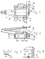
- 1 denotes a pantograph frame, by means of an adjusting device 2 (FIGS. 1 to 3) or by means of a steep device 3 (FIGS. 4 to 6) the inclination of a car body 4 can be traced back by an adjustment angle ⁇ is.
- the Actuator 2 three insulated handlebars 5 to 7.
- Two insulated handlebars 5 and 6 are wide at the corners End face of the pantograph frame 1 is arranged.
- the third insulated handlebar 7 is in the middle of the narrow end the pantograph frame 1 arranged.
- the isolated Handlebars 5 to 7 are direct at one end on the pantograph frame 1 and with its other end directly hinged to the roof 8 of the car body 4.
- the adjusting device 2 of the shown in FIG 1 to 3 Pantograph further includes an actuator 9 with a insulated drive rod 10.
- the insulated drive rod 10 is with its free end directly on the wide end face of the pantograph frame 1 articulated. Still is the actuator 9 with its housing 11 directly on the roof 8 of the Car body 4 articulated.
- the pantograph according to the invention is on both sides of the Current collector frame 1 each an insulated side guide link 12 or 13 arranged. Both side guide arms 12 and 13 are each with one end on the long side the pantograph frame 1 and with its other end on Roof 8 of the car body 4 articulated.
- Pantograph includes the actuator 3 four insulated handlebars 15 to 18, which at the corners of the Current collector frame 1 are arranged.
- the insulated handlebars 15 to 18 are direct at one end on the pantograph frame 1 and with its other end directly hinged to the roof 8 of the car body 4.
- the adjusting device 3 comprises an actuator 19 with an insulated drive rod 20.
- the insulated drive rod 20 is with its free end directly on the in The direction of travel is viewed from the rear end of the pantograph frame 1 articulated.
- the actuator 19 is with his Housing 21 hinged directly to the roof 8 of the car body 4.
- the handlebar shafts 22 and 23 are on bearings 24 to 27 held on the roof 8 of the car body 4. In FIG 8 this is Storage shown in the example of the bearing 25 in detail.
- the handlebar shafts 22 and 23 can according to another, in 1 to 8 not shown embodiment as eccentric shafts be trained.
- the isolated Handlebars 5 to 7 or 15 to 18 adjustable in length be.
- the actuator 9 or 19 has in the illustrated embodiments additional return springs 29 and 30, respectively and a pawl 31 for fixation.
- the retraction springs 29 and 30 cannot according to one in FIGS. 1 to 3 illustrated embodiment also on the isolated side guide arms 12 and 13 may be arranged.
- the retraction springs 29 and 30 serve the pantograph frame 1 in Incident (failure of the actuator 9 or, 19 or damage of the linkage 28) in the middle position, in the then the fixing by means of pawl 31.
- the stake of retraction springs presupposes that as actuators low-friction spindle drives and no worm drives can be used with high friction.
- the current collector frame 1 is shown in FIGS. 4 to 6 Embodiment with a pivotable support 32 for the isolated handlebars 17 and 18 equipped.
- the pivotable support 32 forms together with the insulated Handlebars 15 and 16 a three-point support for the pantograph frame 1. This eliminates mechanical tension the isolated handlebars 15 to 18, the z. B. by tolerances or elasticities on the roof 8 of the body 4 arise, prevented.
- the pivotable support 32 is for this expediently mounted elastically, because inaccuracies caused by assembly, inclination, torsion and temperature dependent coefficients of linear expansion, in each Spatial direction can be balanced.
Landscapes
- Engineering & Computer Science (AREA)
- Power Engineering (AREA)
- Transportation (AREA)
- Mechanical Engineering (AREA)
- Current-Collector Devices For Electrically Propelled Vehicles (AREA)
Abstract
Description
- FIG 1
- eine stirnseitige Ansicht auf eine erste Ausführungsform des erfindungsgemäßen Stromabnehmers,
- FIG 2
- eine Draufsicht auf den Stromabnehmer gemäß FIG 1,
- FIG 3
- eine Seitenansicht auf den Stromabnehmer gemäß FIG 1,
- FIG 4
- eine stirnseitige Ansicht auf eine zweite Ausführungsform des erfindungsgemäßen Stromabnehmers,
- FIG 5
- eine Draufsicht auf den Stromabnehmer gemäß FIG 4,
- FIG 6
- eine Seitenansicht auf den Stromabnehmer gemäß FIG 4,
- FIG 7
- eine Detaildarstellung einer Anlenkung des Stromabnehmergestells an ein Fahrwerk in einer weiteren Ausführungsform,
- FIG 8
- eine Detaildarstellung zu der in FIG 5 und 6 dargestellten Lagerung der Lenkerwelle.
Claims (19)
- Stromabnehmer, der mittels einer Steilvorrichtung (2, 3) entgegen der Neigung eines Wagenkastens (4) um einen Stellwinkel (γ) rückführbar ist, wobei die Stellvorrichtung (2, 3) folgende Merkmale umfaßt:wenigstens einen Stellantrieb (9, 19),-- der eine isolierte Antriebsstange (10, 20) aufweist, die mit ihrem freien Ende direkt an einer der Stirnseiten des Stromabnehmergestells (1), vorzugsweise an der breiten Stirnseite, angelenkt ist,-- und der mit seinem Gehäuse (11, 21) direkt am Dach (8) des Wagenkastens (4) angelenkt istwenigstens zwei isolierte Lenkerstangen (5 - 7, 15 - 18),-- die zu beiden Seiten der Längsachse des Wagenkastens (4) an gegenüberliegenden Ecken des Stromabnehmergestells (1) angeordnet sind-- und die jeweils mit ihrem einen Ende direkt am Stromabnehmergestell (1) und mit ihrem anderen Ende direkt am Dach (8) des Wagenkastens (4) angelenkt sind.
- Stromabnehmer nach Anspruch 1, bei dem der Stellantrieb als elektrischer Stellantrieb ausgebildet ist.
- Stromabnehmer nach Anspruch 1, bei der Stellantrieb als hydraulischer Stellantrieb ausgebildet ist.
- Stromabnehmer nach Anspruch 1, bei dem der Stellantrieb über wenigstens eine mechanische Verbindung (28) mit dem Fahrwerk des Wagenkastens (4) gekoppelt ist.
- Stromabnehmer nach Anspruch 4, bei dem die mechanische Verbindung als Seilzug oder als Gestänge (28) ausgebildet ist.
- Stromabnehmer nach Anspruch 1, bei dem der Stellantrieb über wenigstens eine elektrische Verbindung mit dem Fahrwerk des Wagenkastens (4) gekoppelt ist.
- Stromabnehmer nach Anspruch 1, bei dem die Stellvorrichtung (2) zwei isolierte Lenkerstangen (5, 6), die an den Ekken der breiten Stirnseite angeordnet sind, und eine isolierte Lenkerstange (7), die mittig zur schmalen Stirnseite angeordnet ist und die jeweils mit ihrem einen Ende direkt am Stromabnehmergestell (1) und mit ihrem anderen Ende direkt am Dach (8) des Wagenkastens (4) angelenkt sind.
- Stromabnehmer nach Anspruch 1, bei dem die Stellvorrichtung (3) vier isolierte Lenkerstangen (15 - 18) umfaßt, die an den Ecken des Stromabnehmergestells (1) angeordnet sind und die jeweils mit ihrem einen Ende direkt am Stromabnehmergestell (1) und mit ihrem anderen Ende direkt am Dach (8) des Wagenkastens (4) angelenkt sind.
- Stromabnehmer nach Anspruch 1, bei dem zu beiden Seiten des Stromabnehmergestells (1) jeweils ein Seitenführungslenker (12, 13) angeordnet ist, der jeweils mit seinem einen Ende an der Längsseite des Stromabnehmergestells (1) und mit seinem anderen Ende am Dach (8) des Wagenkastens (4) angelenkt ist.
- Stromabnehmer nach Anspruch 8, bei dem jeweils die beiden isolierten Lenkerstangen (15, 17; 16, 18), die gemeinsam an einer Längsseite des Stromabnehmergestells (1) angeordnet sind, formschlüssig mit einer Lenkerwelle (22, 23) verbunden sind.
- Stromabnehmer nach Anspruch 10, bei dem die Lenkerwellen (22, 23) am Dach (8) des Wagenkastens (4) über Lager (24 - 27) gehaltert sind.
- Stromabnehmer nach Anspruch 10, bei dem die Lenkerwellen im Stromabnehmergestell (1) über Lager gehaltert sind.
- Stromabnehmer nach Anspruch 9, bei dem die isolierten Seitenführungslenker (12, 13) elastisch gelagert sind.
- Stromabnehmer nach Anspruch 11 oder 12, bei dem die Lenkerwellen elastisch gelagert sind.
- Stromabnehmer nach Anspruch 1, bei dem die isolierten Lenkerstangen (5 - 7, 15 - 18) auf dem Dach (8) des Wagenkastens (4) elastisch gelagert sind.
- Stromabnehmer nach Anspruch 1, bei dem die isolierten Lenkerstangen im Stromabnehmergestell (1) elastisch gelagert sind.
- Stromabnehmer nach Anspruch 1, bei dem das Stromabnehmergestell (1) mit einer schwenkbaren Stütze (32) für die isolierten Lenkerstangen (17, 18) ausgerüstet ist.
- Stromabnehmer nach Anspruch 10, bei dem die Lenkerwellen als Exzenterwellen ausgebildet sind.
- Stromabnehmer nach Anspruch 10, bei dem die Lenkerwellen in ihrer Lange verstellbar sind.
Applications Claiming Priority (2)
| Application Number | Priority Date | Filing Date | Title |
|---|---|---|---|
| DE19646178 | 1996-11-08 | ||
| DE1996146178 DE19646178C1 (de) | 1996-11-08 | 1996-11-08 | Stromabnehmer |
Publications (2)
| Publication Number | Publication Date |
|---|---|
| EP0841207A2 true EP0841207A2 (de) | 1998-05-13 |
| EP0841207A3 EP0841207A3 (de) | 1999-07-07 |
Family
ID=7811088
Family Applications (1)
| Application Number | Title | Priority Date | Filing Date |
|---|---|---|---|
| EP97119085A Withdrawn EP0841207A3 (de) | 1996-11-08 | 1997-10-31 | Stromabnehmer |
Country Status (2)
| Country | Link |
|---|---|
| EP (1) | EP0841207A3 (de) |
| DE (1) | DE19646178C1 (de) |
Cited By (1)
| Publication number | Priority date | Publication date | Assignee | Title |
|---|---|---|---|---|
| CN104718118A (zh) * | 2012-09-12 | 2015-06-17 | 勃姆巴迪尔运输有限公司 | 具有声学优化固定的集电装置的轨道车辆 |
Citations (2)
| Publication number | Priority date | Publication date | Assignee | Title |
|---|---|---|---|---|
| JPH04172901A (ja) * | 1990-11-07 | 1992-06-19 | Railway Technical Res Inst | 鉄道車両用二段リンク式パンタグラフ傾斜装置 |
| JPH05130705A (ja) * | 1991-10-31 | 1993-05-25 | Shimadzu Corp | 鉄道車両用集電装置 |
Family Cites Families (1)
| Publication number | Priority date | Publication date | Assignee | Title |
|---|---|---|---|---|
| AT327289B (de) * | 1971-09-08 | 1976-01-26 | Siemens Ag Oesterreich | Schienenfahrzeug mit einem scherenstromabnehmer |
-
1996
- 1996-11-08 DE DE1996146178 patent/DE19646178C1/de not_active Expired - Fee Related
-
1997
- 1997-10-31 EP EP97119085A patent/EP0841207A3/de not_active Withdrawn
Patent Citations (2)
| Publication number | Priority date | Publication date | Assignee | Title |
|---|---|---|---|---|
| JPH04172901A (ja) * | 1990-11-07 | 1992-06-19 | Railway Technical Res Inst | 鉄道車両用二段リンク式パンタグラフ傾斜装置 |
| JPH05130705A (ja) * | 1991-10-31 | 1993-05-25 | Shimadzu Corp | 鉄道車両用集電装置 |
Cited By (2)
| Publication number | Priority date | Publication date | Assignee | Title |
|---|---|---|---|---|
| CN104718118A (zh) * | 2012-09-12 | 2015-06-17 | 勃姆巴迪尔运输有限公司 | 具有声学优化固定的集电装置的轨道车辆 |
| CN104718118B (zh) * | 2012-09-12 | 2017-07-28 | 勃姆巴迪尔运输有限公司 | 具有声学优化固定的集电装置的轨道车辆 |
Also Published As
| Publication number | Publication date |
|---|---|
| EP0841207A3 (de) | 1999-07-07 |
| DE19646178C1 (de) | 1998-07-02 |
Similar Documents
| Publication | Publication Date | Title |
|---|---|---|
| DE2903795C2 (de) | Kopfabschluß einer Flugpassagierverladebrücke | |
| DE102009006387B4 (de) | Vorrichtung zur elektrischen Einstellung eines Fahrzeugsitzes | |
| DE69303138T2 (de) | Einstellbare Lenksäuleneinheit für ein Kraftfahrzeug | |
| DE102020129215A1 (de) | System, Verfahren und Vorrichtung für alternative Stellen für eine Neigungsschwenkachse für eine Steer-By-Wire-Lenk-Säule | |
| DE3536843A1 (de) | Stromabnehmervorrichtung | |
| EP2695790A1 (de) | Dachgelenk für ein mehrgliedriges Fahrzeug | |
| DE69502839T2 (de) | Klemmmechanismus für eine verstellbare lenksäule | |
| DE68903095T2 (de) | Lenkvorrichtung fuer die hinterraeder eines durch vier raeder gelenkten fahrzeuges. | |
| DE4336286C1 (de) | Zahnstangenlenkung für Kraftfahrzeuge | |
| EP0718171B1 (de) | Wankbegrenzer | |
| EP1712443B1 (de) | Mehrgliedriges Gelenkfahrzeug, insbesondere Schienenfahrzeug. | |
| EP1151905B1 (de) | Vorrichtung zur gelenkigen Verbindung von Wagenkästen eines mehrgliedrigen Schienenfahrzeuges | |
| EP0841207A2 (de) | Stromabnehmer | |
| EP0755815B1 (de) | Faltdach für Fahrzeuge | |
| EP0975504B1 (de) | Fahrzeug | |
| EP0892727B1 (de) | Schienenfahrzeug | |
| EP0983931A2 (de) | Verbindung zwischen zwei Fahrzeugteilen eines Gelenkfahrzeuges | |
| DE19615341C2 (de) | Vorrichtung zum Ausrichten eines Stromabnehmers eines Schienenfahrzeuges | |
| DE29613541U1 (de) | Schienenfahrzeug | |
| DE69708444T2 (de) | Wippeaufhängungsvorrichtung für Schienenfahrzeug mit Wagenkasten mit variabler Neigung | |
| EP0990549B1 (de) | Stromabnehmer | |
| EP4263316B1 (de) | Anordnung aus einem kinematikpaket und einem federhebel für ein drehgestell | |
| EP0794101B1 (de) | Schienenfahrzeug mit vier oder sechs in radialer Stellung steuerbaren Radsätzen | |
| DE102024120212B4 (de) | Schließvorrichtung für eine Öffnung eines Kraftfahrzeugs | |
| DE10112513B4 (de) | Armfensterheber für räumlich gekrümmte Fensterscheiben |
Legal Events
| Date | Code | Title | Description |
|---|---|---|---|
| PUAI | Public reference made under article 153(3) epc to a published international application that has entered the european phase |
Free format text: ORIGINAL CODE: 0009012 |
|
| AK | Designated contracting states |
Kind code of ref document: A2 Designated state(s): AT CH DE ES FR GB IT LI PT SE |
|
| PUAL | Search report despatched |
Free format text: ORIGINAL CODE: 0009013 |
|
| AK | Designated contracting states |
Kind code of ref document: A3 Designated state(s): AT BE CH DE DK ES FI FR GB GR IE IT LI LU MC NL PT SE |
|
| RIC1 | Information provided on ipc code assigned before grant |
Free format text: 6B 60L 5/26 A, 6B 60L 5/19 B |
|
| 17P | Request for examination filed |
Effective date: 19990805 |
|
| AKX | Designation fees paid |
Free format text: AT CH DE ES FR GB IT LI PT SE |
|
| 17Q | First examination report despatched |
Effective date: 20061208 |
|
| STAA | Information on the status of an ep patent application or granted ep patent |
Free format text: STATUS: THE APPLICATION HAS BEEN WITHDRAWN |
|
| 18W | Application withdrawn |
Effective date: 20080624 |