EP0841223A1 - Cockpitquerträger in einem Kraftfahrzeug - Google Patents
Cockpitquerträger in einem Kraftfahrzeug Download PDFInfo
- Publication number
- EP0841223A1 EP0841223A1 EP97105303A EP97105303A EP0841223A1 EP 0841223 A1 EP0841223 A1 EP 0841223A1 EP 97105303 A EP97105303 A EP 97105303A EP 97105303 A EP97105303 A EP 97105303A EP 0841223 A1 EP0841223 A1 EP 0841223A1
- Authority
- EP
- European Patent Office
- Prior art keywords
- cross member
- airbag
- cockpit cross
- cockpit
- sensor
- Prior art date
- Legal status (The legal status is an assumption and is not a legal conclusion. Google has not performed a legal analysis and makes no representation as to the accuracy of the status listed.)
- Granted
Links
- 238000009434 installation Methods 0.000 claims description 3
- 238000004519 manufacturing process Methods 0.000 description 4
- 238000004512 die casting Methods 0.000 description 3
- 239000002184 metal Substances 0.000 description 2
- 230000002950 deficient Effects 0.000 description 1
- 230000006870 function Effects 0.000 description 1
- 238000007689 inspection Methods 0.000 description 1
- 230000010354 integration Effects 0.000 description 1
- 238000000465 moulding Methods 0.000 description 1
- 230000001681 protective effect Effects 0.000 description 1
- 230000009993 protective function Effects 0.000 description 1
Images

Classifications
-
- B—PERFORMING OPERATIONS; TRANSPORTING
- B62—LAND VEHICLES FOR TRAVELLING OTHERWISE THAN ON RAILS
- B62D—MOTOR VEHICLES; TRAILERS
- B62D25/00—Superstructure or monocoque structure sub-units; Parts or details thereof not otherwise provided for
- B62D25/08—Front or rear portions
- B62D25/14—Dashboards as superstructure sub-units
- B62D25/145—Dashboards as superstructure sub-units having a crossbeam incorporated therein
Definitions
- the invention relates to a cockpit cross member in one Motor vehicle according to the preamble of claim 1.
- FR 2 704 510 A1 which is defined in the preamble of claim 1 is considered, is a cockpit cross member in one Motor vehicle known with its ends at the Vehicle sides is attached and to stabilize the Motor vehicle stem and as a support for it Components serves. So there is one in a housing Airbag module attached, in which a gas generator is stored is so that the deployment forces of the airbag module and the Load forces on the airbag cover also in the Cockpit cross members are initiated.
- Airbag sensors are usually housed in a housing Longitudinal vehicle tunnel set.
- the object of the invention is to manufacture the equipment of a motor vehicle Passenger airbag system and simplify costs belittling.
- the task is characterized by the characteristic features of the Claim 1 solved.
- a sturdy version provided in the vehicle Cockpit cross member to which an airbag module is fastened which comprises a gas generator and an airbag cover, is also prepared for the determination of the airbag sensor, so that a complete airbag system for the passenger on Cockpit cross member is fixed. Additional space must be in the Motor vehicle will not be kept free, and also the necessary fasteners are kept to a minimum reduced.
- This also makes it possible Cockpit cross member in advance, before installing it in the Motor vehicle stem, with all necessary components for the To equip the passenger airbag, and this airbag system on his Check functionality before installing the cockpit, so that a more cumbersome check within of the motor vehicle is no longer necessary. That too after the Inspection of any replacement that may become defective Components are of course outside due to the accessibility of the motor vehicle easier and faster to handle.
- the molding of the receiving housing is one Die casting crossmember to implement advantageously.
- a housing for the airbag sensor can be used during production of the cockpit cross member are already molded or molded, so that the walls of the cockpit cross member may be together with an end plate provided on the airbag sensor Form an enclosed space in which the airbag sensor is safe Damage and protected from electromagnetic influences lies.
- fixations can be attached to the cockpit cross member be injected so that the airbag module at its Fastening experiences an orientation as it then after installation of the cockpit cross member for the targeted deployment of the Airbag cover is necessary. It can also be provided that Housing for the airbag module in the cockpit cross member to shape what from a cockpit cross member Light metal die casting is possible, so that a separate Airbag housing is saved, and the gas generator and the Airbag cover with the airbag cover directly on the cockpit cross member can be determined and supported.
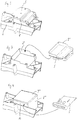
- FIG. 1 shows a cockpit cross member 1 in one Motor vehicle shown in detail in the stem at the level of a Instrument panel aligned in the vehicle transverse direction with each one end 2 or 3 on the left or right side wall of the Motor vehicle e.g. is fixed by a screw connection, and because of its stability to attach the Instrument panel, the heater and other units are used can.
- this cockpit cross member 1 Airbag module 4 and the associated airbag sensor 5 for the Passenger airbag fastened supported by the Cockpit cross member 1 is excited during a crash. So that must Motor vehicle no further space for the airbag sensor 5 be kept clear, and the existing cockpit cross member 1 takes over the protective function against damage to the Airbag sensor 5 and also ensures a cheap Attachment option and secure support of the Airbag modules 4. The effort for equipping the Cockpit cross member 1 with the components of the airbag system thus minimized.
- the airbag module 4 can on the cockpit cross member 1 by this integrally molded locking lugs 6 and molded Fastening holes 7 are fixed so that the airbag module 4 after installing the cockpit cross member 1 in the Motor vehicle stem already occupies the position that one ensures correct deployment of the airbag cover.
- a housing for the passenger airbag can also be in the cockpit cross member 1 is molded during its manufacture, which then includes a gas generator and an airbag cover will.
- a receptacle housing 8 is in the cockpit cross member 1 molded into which the airbag sensor 5, the one equipped Sensor board with electrical connections, can be used is.
- the stable cockpit cross member 1 thus forms Protective housing for the sensitive electronics of the airbag sensor 5 against its damage during driving and in a crash, and also protects it from electromagnetic influences, which the Can influence the function of the airbag sensor 5.
- FIG. 2 an airbag sensor 5 is shown in FIG. 2, which is mounted in a receiving housing 8 ', which by a cover is closed and on the cockpit cross member 1 is screwed on.
- FIG. 3 shows a molded on the cockpit cross member 1 Receiving housing 8 '', in which the airbag sensor 5, the one Circuit board with electronic attachments and a connector includes, is used according to the arrow shown, after which a cover plate 9 '' on the airbag sensor 5 Receptacle housing 8 '' closes on the open side.
- the definition of the airbag module 4 and the airbag sensor 3 together on the cockpit cross member 1 leads to a reduction the installation costs, as the airbag system for the passenger in advance on the cockpit cross member 1 before it is installed in the motor vehicle is installed, and then a check of the Functionality can take place. With that, the Components of the airbag system not individually within the Vehicle body assembled and operatively connected. One after the examination of a replacement that may not be necessary working component can immediately with good accessibility be made.
Landscapes
- Engineering & Computer Science (AREA)
- Chemical & Material Sciences (AREA)
- Combustion & Propulsion (AREA)
- Transportation (AREA)
- Mechanical Engineering (AREA)
- Body Structure For Vehicles (AREA)
- Air Bags (AREA)
- Steering Controls (AREA)
- Window Of Vehicle (AREA)
- Motor Or Generator Frames (AREA)
- Testing Of Balance (AREA)
- Vibration Prevention Devices (AREA)
Abstract
Description
- Fig. 1
- einen gegossenen Cockpitquerträger mit einem daran festlegbaren Airbagmodul und einem eingeformten Aufnahmegehäuse für den Airbagsensor,
- Fig. 2
- einen Cockpitquerträger mit einem daran festgelegten Airbagsensor,
- Fig. 3
- einen Cockpitquerträger mit einem angeformten Aufnahmegehäuse für den Airbagsensor, und
- Fig. 4
- einen Cockpitquerträger mit einem angeformten Aufnahmegehäuse mit einem Aufnahmeschlitz für den Airbagsensor.
Claims (7)
- Cockpitquerträger in einem Kraftfahrzeug, der im Vorbau auf Höhe einer Instrumententafel in Fahrzeugquerrichtung ausgerichtet, mit je einem Ende an den gegenüberliegenden Seiten des Kraftfahrzeugs festgelegt ist, und an dem ein Airbagmodul für den Beifahrer, das einen Gasgenerator und eine Airbaghülle umfaßt, befestigt ist, welches beim Ansprechen eines Airbagsensors aktiviert wird,
dadurch gekennzeichnet,
daß der Airbagsensor (5) am Cockpitquerträger (1) gelagert ist. - Cockpitquerträger nach Anspruch 1,
dadurch gekennzeichnet,
daß in den Cockpitquerträger (1) ein trogförmiges Aufnahmegehäuse (8) für den Airbagsensor (5) eingeformt ist. - Cockpitquerträger nach Anspruch 1,
dadurch gekennzeichnet,
daß an den Cockpitquerträger (1) ein Aufnahmegehäuse (8'', 8''') für den Airbagsensor (5) angeformt ist. - Cockpitquerträger nach einem der Ansprüche 2 oder 3,
dadurch gekennzeichnet,
daß das Aufnahmegehäuse (8, 8'', 8''') durch die Aufnahme des Airbagsensors (5) geschlossen wird. - Cockpitquerträger nach Anspruch 1,
dadurch gekennzeichnet,
daß das Airbagmodul (4) und der Airbagsensor (5) am Cockpitquerträger (1) eine vormontierte Einheit bildend, vor dem Einbau des Cockpitquerträgers (1) auf Funktionstüchtigkeit überprüfbar sind. - Cockpitquerträger nach Anspruch 1,
dadurch gekennzeichnet,
daß der Cockpitquerträger (1) Fixierungen (6, 7) aufweist, durch die das Airbagmodul (4) bei seiner Befestigung selbsttätig ausgerichtet wird. - Cockpitquerträger nach Anspruch 1,
dadurch gekennzeichnet,
daß ein Gehäuse für das Airbagmodul (4) in den Cockpitquerträger (1) eingeformt ist.
Applications Claiming Priority (2)
| Application Number | Priority Date | Filing Date | Title |
|---|---|---|---|
| DE19645895 | 1996-11-07 | ||
| DE19645895A DE19645895C2 (de) | 1996-11-07 | 1996-11-07 | Traganordnung für eine Lenkwelle eines Kraftahrzeuges |
Publications (2)
| Publication Number | Publication Date |
|---|---|
| EP0841223A1 true EP0841223A1 (de) | 1998-05-13 |
| EP0841223B1 EP0841223B1 (de) | 2001-05-02 |
Family
ID=7810905
Family Applications (3)
| Application Number | Title | Priority Date | Filing Date |
|---|---|---|---|
| EP97105303A Expired - Lifetime EP0841223B1 (de) | 1996-11-07 | 1997-03-27 | Cockpitquerträger in einem Kraftfahrzeug |
| EP97105304A Expired - Lifetime EP0841241B1 (de) | 1996-11-07 | 1997-03-27 | Cockpitquerträger in einem Kraftfahrzeug |
| EP97119027A Expired - Lifetime EP0841242B1 (de) | 1996-11-07 | 1997-10-31 | Traganordnung für eine Lenkwelle eines Kraftfahrzeuges |
Family Applications After (2)
| Application Number | Title | Priority Date | Filing Date |
|---|---|---|---|
| EP97105304A Expired - Lifetime EP0841241B1 (de) | 1996-11-07 | 1997-03-27 | Cockpitquerträger in einem Kraftfahrzeug |
| EP97119027A Expired - Lifetime EP0841242B1 (de) | 1996-11-07 | 1997-10-31 | Traganordnung für eine Lenkwelle eines Kraftfahrzeuges |
Country Status (6)
| Country | Link |
|---|---|
| EP (3) | EP0841223B1 (de) |
| JP (1) | JPH10157633A (de) |
| KR (1) | KR100293113B1 (de) |
| AT (1) | ATE202750T1 (de) |
| DE (3) | DE19645895C2 (de) |
| ES (3) | ES2154430T3 (de) |
Families Citing this family (6)
| Publication number | Priority date | Publication date | Assignee | Title |
|---|---|---|---|---|
| FR2800031B1 (fr) | 1999-10-22 | 2001-11-16 | Renault | Traverse de planche de bord |
| DE10320258B3 (de) * | 2003-05-07 | 2004-09-09 | Daimlerchrysler Ag | Trageeinrichtung für eine Lenkwelle eines Kraftfahrzeuges |
| DE102009057057A1 (de) | 2009-12-04 | 2011-06-09 | Volkswagen Ag | Cockpitquerträgeranordnung, Lenkungsanordnung und Kraftfahrzeug |
| FR3056958B1 (fr) * | 2016-10-05 | 2018-11-02 | Renault S.A.S | Vehicule automobile comprenant un support supportant un ensemble d'essuie-glace et une colonne de direction |
| FR3101316A1 (fr) * | 2019-09-26 | 2021-04-02 | Psa Automobiles Sa | Dispositif de fixation commun pour une colonne de direction et un équipement d’un véhicule |
| FR3141391A1 (fr) * | 2022-10-28 | 2024-05-03 | Faurecia Interieur Industrie | Ensemble de planche de bord comprenant un dispositif d’affichage en porte-à-faux |
Citations (5)
| Publication number | Priority date | Publication date | Assignee | Title |
|---|---|---|---|---|
| DE1942154A1 (de) * | 1968-08-20 | 1970-02-26 | Eaton Yale & Towne | Kollisionssensor |
| EP0199024A2 (de) * | 1985-04-19 | 1986-10-29 | Ag Audi | Fahrzeug mit einer Sicherheitseinrichtung für den Fahrzeuglenker |
| DE4328721A1 (de) * | 1993-08-26 | 1995-03-02 | Opel Adam Ag | Anordnung eines Airbagmoduls an der Beifahrerseite eines Kraftfahrzeugs und Verfahren zur Montage eines Airbagmoduls |
| JPH07309196A (ja) * | 1994-05-18 | 1995-11-28 | Nippondenso Co Ltd | エアバッグ装置 |
| US5498025A (en) * | 1994-04-26 | 1996-03-12 | General Motors Corporation | Air bag module |
Family Cites Families (8)
| Publication number | Priority date | Publication date | Assignee | Title |
|---|---|---|---|---|
| DE2313115A1 (de) * | 1973-03-16 | 1974-09-19 | Daimler Benz Ag | Halterung fuer die lenksaeule eines kraftfahrzeuges |
| US4241937A (en) * | 1979-03-26 | 1980-12-30 | General Motors Corporation | Steering column support |
| FR2605965B1 (fr) * | 1986-10-30 | 1991-01-11 | Peugeot | Colonne de direction de vehicule pre-assemblee |
| FR2655307B1 (fr) * | 1989-12-06 | 1992-04-03 | Ecia Equip Composants Ind Auto | Piece de structure perfectionnee pour vehicule et son application a un assemblage automatique. |
| FR2661883B1 (fr) * | 1990-05-11 | 1992-07-17 | Renault | Structure plastique de separation entre l'habitacle et le compartiment moteur d'un vehicule automobile. |
| DE4410082C2 (de) * | 1994-03-23 | 1997-07-03 | Vaw Ver Aluminium Werke Ag | Träger für die Lenksäule eines Kraftfahrzeuges |
| US5445407A (en) * | 1994-05-24 | 1995-08-29 | General Motors Corporation | Air bag module |
| FR2726520B1 (fr) * | 1994-11-07 | 1997-01-03 | Renault | Dispositif de protection des membres inferieurs du conducteur et d'un ou plusieurs passagers avant d'un vehicule |
-
1996
- 1996-11-07 DE DE19645895A patent/DE19645895C2/de not_active Expired - Fee Related
-
1997
- 1997-03-27 DE DE59702809T patent/DE59702809D1/de not_active Expired - Lifetime
- 1997-03-27 DE DE59703466T patent/DE59703466D1/de not_active Expired - Lifetime
- 1997-03-27 ES ES97105304T patent/ES2154430T3/es not_active Expired - Lifetime
- 1997-03-27 EP EP97105303A patent/EP0841223B1/de not_active Expired - Lifetime
- 1997-03-27 ES ES97105303T patent/ES2158397T3/es not_active Expired - Lifetime
- 1997-03-27 EP EP97105304A patent/EP0841241B1/de not_active Expired - Lifetime
- 1997-10-31 ES ES97119027T patent/ES2161406T3/es not_active Expired - Lifetime
- 1997-10-31 AT AT97119027T patent/ATE202750T1/de not_active IP Right Cessation
- 1997-10-31 EP EP97119027A patent/EP0841242B1/de not_active Expired - Lifetime
- 1997-11-06 KR KR1019970058269A patent/KR100293113B1/ko not_active Expired - Fee Related
- 1997-11-07 JP JP9320603A patent/JPH10157633A/ja active Pending
Patent Citations (6)
| Publication number | Priority date | Publication date | Assignee | Title |
|---|---|---|---|---|
| DE1942154A1 (de) * | 1968-08-20 | 1970-02-26 | Eaton Yale & Towne | Kollisionssensor |
| EP0199024A2 (de) * | 1985-04-19 | 1986-10-29 | Ag Audi | Fahrzeug mit einer Sicherheitseinrichtung für den Fahrzeuglenker |
| DE4328721A1 (de) * | 1993-08-26 | 1995-03-02 | Opel Adam Ag | Anordnung eines Airbagmoduls an der Beifahrerseite eines Kraftfahrzeugs und Verfahren zur Montage eines Airbagmoduls |
| US5498025A (en) * | 1994-04-26 | 1996-03-12 | General Motors Corporation | Air bag module |
| JPH07309196A (ja) * | 1994-05-18 | 1995-11-28 | Nippondenso Co Ltd | エアバッグ装置 |
| US5709403A (en) * | 1994-05-18 | 1998-01-20 | Nippondenso Co., Ltd. | Airbag device provided with airbags located on driver's seat side and passenger's seat side |
Also Published As
| Publication number | Publication date |
|---|---|
| KR19980042121A (ko) | 1998-08-17 |
| JPH10157633A (ja) | 1998-06-16 |
| EP0841242A2 (de) | 1998-05-13 |
| EP0841223B1 (de) | 2001-05-02 |
| DE19645895A1 (de) | 1998-05-14 |
| EP0841242A3 (de) | 1998-07-15 |
| KR100293113B1 (ko) | 2001-06-15 |
| EP0841241A1 (de) | 1998-05-13 |
| DE59703466D1 (de) | 2001-06-07 |
| ES2161406T3 (es) | 2001-12-01 |
| EP0841242B1 (de) | 2001-07-04 |
| EP0841241B1 (de) | 2000-12-27 |
| ES2154430T3 (es) | 2001-04-01 |
| DE59702809D1 (de) | 2001-02-01 |
| ATE202750T1 (de) | 2001-07-15 |
| DE19645895C2 (de) | 1998-08-20 |
| ES2158397T3 (es) | 2001-09-01 |
Similar Documents
| Publication | Publication Date | Title |
|---|---|---|
| DE102013107646B4 (de) | Vorspannungssystem für ein Sicherheitsgurtrückhaltesystem und Gerät für eine Fahrzeugsitzanordnung | |
| DE102009040896B4 (de) | Anordnung zur Befestigung einer Antriebsbaugruppe im Motorraum eines Fahrzeugs | |
| DE102020100338B4 (de) | Strukturelles Armaturenbrettelement für eine Armaturenbrettanordnung | |
| DE10125620A1 (de) | Wartungsfreundliches Lenksäulenmodul | |
| DE102021119577A1 (de) | Modulares Bausatzsystem zum Umrüsten eines Fahrantriebs eines Kraftfahrzeugs von einem Verbrennungsmotor auf einen elektrischen Fahrantrieb, dafür vorgesehene Trägerstruktur, Kraftfahrzeug mit dem Bausatzsystem und Umrüstverfahren | |
| DE102018129034B4 (de) | Vorderwagenstruktur für ein Kraftfahrzeug | |
| EP0841223B1 (de) | Cockpitquerträger in einem Kraftfahrzeug | |
| DE102015015962A1 (de) | Einbaustruktur für eine in einem Fahrzeug montierte Vorrichtung | |
| DE19610529A1 (de) | Anordnung eines Beifahrer-Airbags | |
| DE102010047160B4 (de) | Anordnung zur Befestigung einer Vibrationseinheit an einem Lenkrad | |
| DE102013221134A1 (de) | Befestigungsanordnung für eine Batterie in einem Kraftfahrzeug | |
| DE102024119845B4 (de) | Vordere Rahmenstruktur für ein Elektrofahrzeug mit Längsträgern und zugeordnetem Stützelement zur Lagerung eines Elektromotors sowie Elektrofahrzeug mit einer solchen Rahmenstruktur | |
| EP0999098A2 (de) | Kraftfahrzeug mit einem Sicherungskasten | |
| DE102016100453B4 (de) | Montagehilfe und Verfahren zum Montieren eines Gassackes mittels einer Montagehilfe | |
| EP0849124B1 (de) | Fahrzeuglenkrad mit Airbagmodul | |
| DE10239601A1 (de) | Auf einem Halteteil angebrachter elektronischer Aufprallsensor | |
| EP0832791A2 (de) | Gassack-Modul für ein Fahrzeuginsassen-Rückhaltesystem | |
| DE19835580C1 (de) | Geräteanordnung für ein Kraftfahrzeug | |
| DE602004007612T2 (de) | Vorrichtung zur Erkennung von Hindernissen in der Umgebung eines Fahrzeugs | |
| DE102009059932A1 (de) | Befestigungsvorrichtung zum Befestigen eines Schaltermoduls an einer Lenksäule eines Kraftfahrzeugs | |
| EP0521850B1 (de) | Anordnung zur anbringung eines airbag in einem fahrzeuglenkrad | |
| DE102023107028B4 (de) | Lenkrad für ein Fahrzeug, Fahrzeug und elektronische Baugruppe | |
| DE60026812T2 (de) | Feststellbremsgehäuse für ein Kraftfahrzeug und Montageverfahren dieses Gehäuses | |
| EP0932329A1 (de) | Anordnung zum lösbaren Befestigen eines quaderförmigen, elektronischen Registriergerätes | |
| DE2339637A1 (de) | Anhaengevorrichtung |
Legal Events
| Date | Code | Title | Description |
|---|---|---|---|
| PUAI | Public reference made under article 153(3) epc to a published international application that has entered the european phase |
Free format text: ORIGINAL CODE: 0009012 |
|
| AK | Designated contracting states |
Kind code of ref document: A1 Designated state(s): DE ES FR GB IT |
|
| AX | Request for extension of the european patent |
Free format text: AL;LT;LV;RO;SI |
|
| RAP1 | Party data changed (applicant data changed or rights of an application transferred) |
Owner name: MICRO COMPACT CAR AG |
|
| 17P | Request for examination filed |
Effective date: 19980820 |
|
| AKX | Designation fees paid |
Free format text: DE ES FR GB IT |
|
| RBV | Designated contracting states (corrected) |
Designated state(s): DE ES FR GB IT |
|
| RAP1 | Party data changed (applicant data changed or rights of an application transferred) |
Owner name: MICRO COMPACT CAR SMART GMBH |
|
| 17Q | First examination report despatched |
Effective date: 19991104 |
|
| GRAG | Despatch of communication of intention to grant |
Free format text: ORIGINAL CODE: EPIDOS AGRA |
|
| GRAG | Despatch of communication of intention to grant |
Free format text: ORIGINAL CODE: EPIDOS AGRA |
|
| GRAH | Despatch of communication of intention to grant a patent |
Free format text: ORIGINAL CODE: EPIDOS IGRA |
|
| GRAH | Despatch of communication of intention to grant a patent |
Free format text: ORIGINAL CODE: EPIDOS IGRA |
|
| GRAA | (expected) grant |
Free format text: ORIGINAL CODE: 0009210 |
|
| ITF | It: translation for a ep patent filed | ||
| AK | Designated contracting states |
Kind code of ref document: B1 Designated state(s): DE ES FR GB IT |
|
| REF | Corresponds to: |
Ref document number: 59703466 Country of ref document: DE Date of ref document: 20010607 |
|
| GBT | Gb: translation of ep patent filed (gb section 77(6)(a)/1977) |
Effective date: 20010524 |
|
| ET | Fr: translation filed | ||
| REG | Reference to a national code |
Ref country code: ES Ref legal event code: FG2A Ref document number: 2158397 Country of ref document: ES Kind code of ref document: T3 |
|
| REG | Reference to a national code |
Ref country code: GB Ref legal event code: IF02 |
|
| PLBE | No opposition filed within time limit |
Free format text: ORIGINAL CODE: 0009261 |
|
| STAA | Information on the status of an ep patent application or granted ep patent |
Free format text: STATUS: NO OPPOSITION FILED WITHIN TIME LIMIT |
|
| 26N | No opposition filed | ||
| PGFP | Annual fee paid to national office [announced via postgrant information from national office to epo] |
Ref country code: ES Payment date: 20060329 Year of fee payment: 10 |
|
| GBPC | Gb: european patent ceased through non-payment of renewal fee |
Effective date: 20070327 |
|
| PG25 | Lapsed in a contracting state [announced via postgrant information from national office to epo] |
Ref country code: GB Free format text: LAPSE BECAUSE OF NON-PAYMENT OF DUE FEES Effective date: 20070327 |
|
| REG | Reference to a national code |
Ref country code: ES Ref legal event code: FD2A Effective date: 20070328 |
|
| PG25 | Lapsed in a contracting state [announced via postgrant information from national office to epo] |
Ref country code: ES Free format text: LAPSE BECAUSE OF NON-PAYMENT OF DUE FEES Effective date: 20070328 |
|
| PGFP | Annual fee paid to national office [announced via postgrant information from national office to epo] |
Ref country code: GB Payment date: 20060322 Year of fee payment: 10 |
|
| REG | Reference to a national code |
Ref country code: FR Ref legal event code: TP Ref country code: FR Ref legal event code: CD Ref country code: FR Ref legal event code: CA |
|
| PGFP | Annual fee paid to national office [announced via postgrant information from national office to epo] |
Ref country code: IT Payment date: 20120327 Year of fee payment: 16 |
|
| PGFP | Annual fee paid to national office [announced via postgrant information from national office to epo] |
Ref country code: DE Payment date: 20120531 Year of fee payment: 16 |
|
| PGFP | Annual fee paid to national office [announced via postgrant information from national office to epo] |
Ref country code: FR Payment date: 20120417 Year of fee payment: 16 |
|
| REG | Reference to a national code |
Ref country code: FR Ref legal event code: ST Effective date: 20131129 |
|
| REG | Reference to a national code |
Ref country code: DE Ref legal event code: R119 Ref document number: 59703466 Country of ref document: DE Effective date: 20131001 |
|
| PG25 | Lapsed in a contracting state [announced via postgrant information from national office to epo] |
Ref country code: FR Free format text: LAPSE BECAUSE OF NON-PAYMENT OF DUE FEES Effective date: 20130402 Ref country code: DE Free format text: LAPSE BECAUSE OF NON-PAYMENT OF DUE FEES Effective date: 20131001 |
|
| PG25 | Lapsed in a contracting state [announced via postgrant information from national office to epo] |
Ref country code: IT Free format text: LAPSE BECAUSE OF NON-PAYMENT OF DUE FEES Effective date: 20130327 |