EP0841551A2 - Mesure de fuite dans une emballage flexible - Google Patents
Mesure de fuite dans une emballage flexible Download PDFInfo
- Publication number
- EP0841551A2 EP0841551A2 EP97308968A EP97308968A EP0841551A2 EP 0841551 A2 EP0841551 A2 EP 0841551A2 EP 97308968 A EP97308968 A EP 97308968A EP 97308968 A EP97308968 A EP 97308968A EP 0841551 A2 EP0841551 A2 EP 0841551A2
- Authority
- EP
- European Patent Office
- Prior art keywords
- vacuum
- chamber
- test
- evacuated
- package
- Prior art date
- Legal status (The legal status is an assumption and is not a legal conclusion. Google has not performed a legal analysis and makes no representation as to the accuracy of the status listed.)
- Withdrawn
Links
Images

Classifications
-
- G—PHYSICS
- G01—MEASURING; TESTING
- G01M—TESTING STATIC OR DYNAMIC BALANCE OF MACHINES OR STRUCTURES; TESTING OF STRUCTURES OR APPARATUS, NOT OTHERWISE PROVIDED FOR
- G01M3/00—Investigating fluid-tightness of structures
- G01M3/02—Investigating fluid-tightness of structures by using fluid or vacuum
- G01M3/36—Investigating fluid-tightness of structures by using fluid or vacuum by detecting change in dimensions of the structure being tested
- G01M3/363—Investigating fluid-tightness of structures by using fluid or vacuum by detecting change in dimensions of the structure being tested the structure being removably mounted in a test cell
Definitions
- the present invention relates to the measurement of leaks in flexible gas-filled packaging and is concerned in particular with an apparatus and method for this purpose.
- the principal requirement of packaging is the protection of the product and this is particularly important in connection with the packaging of food, pharmaceuticals and medical products.
- the increasingly stringent demands on packaging to protect the packaged product for longer periods of time has required the development of better testing methods to remove subjective judgements.
- the known method for testing the integrity of flexible gas-filled packaging involves measuring the force generated by such a gas filled flexible package when the surrounding space is evacuated.
- the principle of operation of this known technique is illustrated in Fig. 1 of the accompanying drawings.
- the package 10 to be tested is placed within a recess in an infill component 12 on a strain gauge platform 14 supported by a base casting 16.
- a pressure plate 18 is applied to the top of the package, the whole of this apparatus being contained with a vacuum chamber 20.
- the pressure plate 18 is attached to a lid of the vacuum chamber 20, which can be opened to enable insertion and removal of the package 10.
- the chamber is evacuated by means of a pump and the force generated by the resulting expansion of the package is measured by a strain gauge coupled to the strain gauge platform 14.
- the package has no leaks, then, if the vacuum is substantially constant, one expects the package force to be correspondingly substantially constant. On the other hand, if there is a hole in the package, gas will escape and the measured force will decay or, in an extreme case, the package will not expand at all.
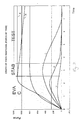
- Fig. 2 of the accompanying drawings shows graphs illustrating typical cases of (A) good pack, (B) small leak, (C) medium leak, (D) medium to large leak, and (E) large leak.
- Fig. 3 of the accompanying drawings shows an implementation of the known technique in a practical machine. Equivalent parts in Figs 1 and 3 are given the same reference numbers.
- the apparatus of Fig. 3 includes a rigid housing 22 defining the vacuum chamber 20, the housing having a hinged lid 24 for enabling access to the housing interior.
- the pack 10 is loaded, the lid 24 closed and the test sequence initiated by the pressing of a button.
- a green light or red light is activated and the result detail and test statistics are displayed for rapid reference.
- the test statistics can be downloaded via an interface port for remote processing at an external computer.
- the vacuum chamber containing a test package is arranged to be subjected to a predetermined vacuum level more rapidly than is possible using the known apparatus having a vacuum pump simply connected to the test chamber.
- the vacuum chamber containing a test package is arranged to be subjected to a vacuum step to achieve rapid application of vacuum to the test chamber.
- this rapid application of the vacuum is achieved by the use of a pre-evacuated chamber which can be connected abruptly to the test chamber via a controllable valve.
- the volume of the pre-evacuated chamber is much greater than that of the internal free space in the test chamber, preferably at least three times as big, so that the connection of the two together does not in itself cause a significant reduction in the vacuum level.
- the volume of the pre-evacuated chamber would be at least five times as big as that of the test chamber.
- the apparatus of the present invention preferably includes a means for close analysis of the force generation and decay curves such that the rate of change of the generated force relative to the rate of change of vacuum may be employed to determine the degree of leak integrity of the pack under test, where the increase in force (or lack of) is a function of the resolution of the change in vacuum and the escape of air from the pack.
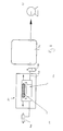
- the embodiment in accordance with the present invention includes a vacuum chamber 30 which is exactly the same as the apparatus of Fig. 3, wherein a test pack 10 is placed on a strain gauge transducer 14 and the expansion force generated thereby under vacuum is monitored.
- the test pack is of the porous type described hereinbefore.
- the vacuum chamber is connected to the vacuum pump 32 via an evacuated reservoir 36 whose volume is large compared to the internal free space volume of the test chamber 30.
- the reservoir 36 is connected to the test chamber via a coupling 34 which provides a minimum of resistance/throttling therebetween.
- a solenoid valve 38 Disposed in the pipework coupling 34 is a solenoid valve 38 which can provide substantially instant communication between the evacuated reservoir 36 and the test chamber 30.
- the test chamber is also connected to a solenoid dump valve 40 to enable its vacuum to be released following a test.
- the pre-evacuated reservoir 36 which is of large volume compared to the test chamber and the good, controlled connection between the two, enables a vacuum to be established in the test chamber very much more rapidly that was possible with the known apparatus. It has been found that, by the application of such a rapidly generated high and stable vacuum to the test chamber containing the test package, a force is initially generated, and then decays in characteristic and distinguishable ways. The test thereby involves analysis of the force generated and decay data rather more closely than simply setting pass/fail levels as previously.
- the chamber 36 and relatively small pump 32 can be replaced by a sufficiently large vacuum pump which itself can generate a sufficient vacuum step for the present purposes.
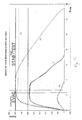
- Fig. 5 shows a typical test result using the apparatus of Fig. 4, where curve G shows the vacuum level in the test chamber, curve H shows the force from a good pack, curve K shows the force from a strongly leaking pack, and curve J shows the force from a slowly leaking pack, where a point occurs when the leakage from the pack balances the ability of the vacuum to generate an increasing force.
Landscapes
- Physics & Mathematics (AREA)
- General Physics & Mathematics (AREA)
- Examining Or Testing Airtightness (AREA)
Applications Claiming Priority (2)
| Application Number | Priority Date | Filing Date | Title |
|---|---|---|---|
| GB9623456 | 1996-11-09 | ||
| GBGB9623456.2A GB9623456D0 (en) | 1996-11-09 | 1996-11-09 | Leak measurement in flexible packaging |
Publications (2)
| Publication Number | Publication Date |
|---|---|
| EP0841551A2 true EP0841551A2 (fr) | 1998-05-13 |
| EP0841551A3 EP0841551A3 (fr) | 1999-02-17 |
Family
ID=10802762
Family Applications (1)
| Application Number | Title | Priority Date | Filing Date |
|---|---|---|---|
| EP97308968A Withdrawn EP0841551A3 (fr) | 1996-11-09 | 1997-11-07 | Mesure de fuite dans une emballage flexible |
Country Status (2)
| Country | Link |
|---|---|
| EP (1) | EP0841551A3 (fr) |
| GB (1) | GB9623456D0 (fr) |
Cited By (3)
| Publication number | Priority date | Publication date | Assignee | Title |
|---|---|---|---|---|
| EP1469296A1 (fr) * | 2003-04-14 | 2004-10-20 | Lorenzo Campanini | Procédé et dispositif d'essai de scellement ou d'étanchéité d'un emballage fabriqué à partir d'un matériau flexible ou semi-rigide |
| DE102006005257A1 (de) * | 2006-02-02 | 2007-08-16 | Indat Systems + Research Gmbh | Vorrichtung zur Messung der Dichtigkeit einer Verpackung |
| WO2012007190A1 (fr) * | 2010-07-15 | 2012-01-19 | Piotec Limited | Appareil de détection de fuite et système de mise sous vide associé |
Family Cites Families (3)
| Publication number | Priority date | Publication date | Assignee | Title |
|---|---|---|---|---|
| FR2351400A1 (fr) * | 1976-05-10 | 1977-12-09 | Lesieur Cotelle | Procede et appareil de controle et de selection de conditionnements comportant des emballages scelles |
| JPH0257533A (ja) * | 1988-08-22 | 1990-02-27 | Taiyo Fishery Co Ltd | 密閉容器のリーク検査方法 |
| US5226316A (en) * | 1992-03-20 | 1993-07-13 | Oscar Mayer Foods Corporation | Package leak detection |
-
1996
- 1996-11-09 GB GBGB9623456.2A patent/GB9623456D0/en active Pending
-
1997
- 1997-11-07 EP EP97308968A patent/EP0841551A3/fr not_active Withdrawn
Cited By (3)
| Publication number | Priority date | Publication date | Assignee | Title |
|---|---|---|---|---|
| EP1469296A1 (fr) * | 2003-04-14 | 2004-10-20 | Lorenzo Campanini | Procédé et dispositif d'essai de scellement ou d'étanchéité d'un emballage fabriqué à partir d'un matériau flexible ou semi-rigide |
| DE102006005257A1 (de) * | 2006-02-02 | 2007-08-16 | Indat Systems + Research Gmbh | Vorrichtung zur Messung der Dichtigkeit einer Verpackung |
| WO2012007190A1 (fr) * | 2010-07-15 | 2012-01-19 | Piotec Limited | Appareil de détection de fuite et système de mise sous vide associé |
Also Published As
| Publication number | Publication date |
|---|---|
| GB9623456D0 (en) | 1997-01-08 |
| EP0841551A3 (fr) | 1999-02-17 |
Similar Documents
| Publication | Publication Date | Title |
|---|---|---|
| DK2502043T3 (en) | Rest vacuum state of a method and system for vacuum degradation leakage testing | |
| US5082366A (en) | Apparatus and method for detecting leaks in packages | |
| EP0561645B1 (fr) | Détection de fuites d'un emballage | |
| KR100309361B1 (ko) | 누설검출방법및장치 | |
| US4663964A (en) | Electronic airtightness tester | |
| JP4410854B2 (ja) | 包装材のシール性の検査 | |
| US5150605A (en) | Package integrity detection method | |
| EP1469295A3 (fr) | Méthode et appareil pour tester une fuite | |
| JPH03195935A (ja) | 漏洩を検出する装置および方法 | |
| JPH09178604A (ja) | 容器の漏れ試験方法及び装置 | |
| EP0168972B1 (fr) | Méthode et dispositif du contrôle d'herméticité | |
| MY108772A (en) | Detection medium and method for use in hermetic seal testing | |
| JP2583880B2 (ja) | パックの気密性検査方法及び装置 | |
| JPH10185752A (ja) | 密封体の漏れ検査方法および装置 | |
| DK166106B (da) | Fremgangsmaade til maaling af trykket i en vakuum-pakning | |
| JPH0121450B2 (fr) | ||
| CA1333530C (fr) | Methode et appareil de detection des fuites dans les emballages sous vide | |
| US20030033857A1 (en) | Apparatus and method to detect leaks in sealed packages | |
| JPH07187152A (ja) | 密封袋のリークテスト方法 | |
| JP3383633B2 (ja) | リーク検査装置 | |
| CA1114642A (fr) | Detecteur pneumatique de pertes par dispersion | |
| JPS5941135B2 (ja) | リ−ク試験装置 | |
| RU2206879C1 (ru) | Способ испытания изделий на герметичность | |
| US6634215B1 (en) | Method for integrally detecting leaks in test pieces with relatively thin walls | |
| JPS62198727A (ja) | 油圧漏洩検出方法 |
Legal Events
| Date | Code | Title | Description |
|---|---|---|---|
| PUAI | Public reference made under article 153(3) epc to a published international application that has entered the european phase |
Free format text: ORIGINAL CODE: 0009012 |
|
| AK | Designated contracting states |
Kind code of ref document: A2 Designated state(s): AT BE CH DE DK ES FI FR GB GR IE IT LI LU MC NL PT SE |
|
| AX | Request for extension of the european patent |
Free format text: AL;LT;LV;RO;SI |
|
| PUAL | Search report despatched |
Free format text: ORIGINAL CODE: 0009013 |
|
| AK | Designated contracting states |
Kind code of ref document: A3 Designated state(s): AT BE CH DE DK ES FI FR GB GR IE IT LI LU MC NL PT SE |
|
| AX | Request for extension of the european patent |
Free format text: AL;LT;LV;RO;SI |
|
| AKX | Designation fees paid | ||
| STAA | Information on the status of an ep patent application or granted ep patent |
Free format text: STATUS: THE APPLICATION IS DEEMED TO BE WITHDRAWN |
|
| 18D | Application deemed to be withdrawn |
Effective date: 19990818 |
|
| REG | Reference to a national code |
Ref country code: DE Ref legal event code: 8566 |