EP0841642A2 - Vorrichtung zur Bearbeitung von Blattgut - Google Patents
Vorrichtung zur Bearbeitung von Blattgut Download PDFInfo
- Publication number
- EP0841642A2 EP0841642A2 EP97308015A EP97308015A EP0841642A2 EP 0841642 A2 EP0841642 A2 EP 0841642A2 EP 97308015 A EP97308015 A EP 97308015A EP 97308015 A EP97308015 A EP 97308015A EP 0841642 A2 EP0841642 A2 EP 0841642A2
- Authority
- EP
- European Patent Office
- Prior art keywords
- motor
- sheets
- pick
- stepper motor
- pulse generator
- Prior art date
- Legal status (The legal status is an assumption and is not a legal conclusion. Google has not performed a legal analysis and makes no representation as to the accuracy of the status listed.)
- Ceased
Links
Images

Classifications
-
- B—PERFORMING OPERATIONS; TRANSPORTING
- B65—CONVEYING; PACKING; STORING; HANDLING THIN OR FILAMENTARY MATERIAL
- B65H—HANDLING THIN OR FILAMENTARY MATERIAL, e.g. SHEETS, WEBS, CABLES
- B65H5/00—Feeding articles separated from piles; Feeding articles to machines
-
- G—PHYSICS
- G07—CHECKING-DEVICES
- G07D—HANDLING OF COINS OR VALUABLE PAPERS, e.g. TESTING, SORTING BY DENOMINATIONS, COUNTING, DISPENSING, CHANGING OR DEPOSITING
- G07D11/00—Devices accepting coins; Devices accepting, dispensing, sorting or counting valuable papers
- G07D11/10—Mechanical details
-
- B—PERFORMING OPERATIONS; TRANSPORTING
- B65—CONVEYING; PACKING; STORING; HANDLING THIN OR FILAMENTARY MATERIAL
- B65H—HANDLING THIN OR FILAMENTARY MATERIAL, e.g. SHEETS, WEBS, CABLES
- B65H2513/00—Dynamic entities; Timing aspects
- B65H2513/10—Speed
-
- B—PERFORMING OPERATIONS; TRANSPORTING
- B65—CONVEYING; PACKING; STORING; HANDLING THIN OR FILAMENTARY MATERIAL
- B65H—HANDLING THIN OR FILAMENTARY MATERIAL, e.g. SHEETS, WEBS, CABLES
- B65H2557/00—Means for control not provided for in groups B65H2551/00 - B65H2555/00
- B65H2557/30—Control systems architecture or components, e.g. electronic or pneumatic modules; Details thereof
- B65H2557/33—Control systems architecture or components, e.g. electronic or pneumatic modules; Details thereof for digital control, e.g. for generating, counting or comparing pulses
Definitions
- This invention relates to sheet handling apparatus for picking sheets from one or more stacks of sheets and presenting the picked sheets to an outlet point.
- the invention has application in cash dispenser units provided as part of automatic teller machines (ATMs).
- ATMs automatic teller machines
- Such units dispense currency notes and include one or more cassette holders for cassettes each containing a stack of currency notes of a particular denomination, usually with different cassettes containing notes of different denominations.
- Pick mechanisms are associated with each cassette holder to pick notes from the stacks in the cassettes. The notes are then carried by suitable transport means to an outlet point for removal by the customer.
- the pick mechanisms may include suction pads for picking the notes one by one from the cassettes and the suction pads are made operational by connection to a vacuum pump.
- An example of a pick mechanism is described in European Patent Application No. 486251A.
- a suitably powerful electric motor is required to operate the pump as well as to provide motive power to sheet transport means to carry the notes away from the pick mechanisms. It is also desirable to be able to accurately position the notes when they approach the outlet point. This requirement would be satisfied by using a stepper motor to drive the transport means. However using a stepper motor as the sole source of motive power for the entire apparatus would require a large and hence expensive motor and associated pulse generator.
- a conventional (and cheaper) ac induction motor is used to operate the vacuum pump and drive the initial part of the sheet transport and the function of the stepper motor is limited to drive the final part of the transport, then problems will occur at the point at which the notes cross over from one drive to the other. If the initial transport is running more slowly than the final transport then the notes are at risk of being ripped, particularly if they already have a small tear. Conversely if the initial transport is running faster than the final transport then the notes are liable to crumple and cause a jam. With a conventional ac induction motor the speed tolerance may be as much as ⁇ 20% depending on load.
- the further pulse generator may comprise an optical disc coupled to rotate with the first motor and an optical sensor positioned close to the disc to generate pulses as the disc rotates.
- Preferably sheet holding means is provided for temporarily holding in a stack the sheets that pass along the presenter transport, and means for returning the stack of sheets in the holding means back to the presenter means for transfer to the outlet point.
- the pick transport means and the presenter transport means preferably each include respective conveyor belts for carrying sheets picked from the stacks, the belts being separated from each other by a gap narrow enough to allow picked sheets to pass from one belt to the next.
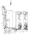
- Fig. 1 there is shown therein sheet handling apparatus and more specifically a cash dispenser unit which forms part of an ATM.
- the unit includes two cassettes 1 and 2 each designed to hold a stack of sheets which in the case of a cash dispenser unit will comprise currency notes. It is likely, but not essential, that the two cassettes will hold notes of different sizes and denominations. Also while two cassettes are illustrated a greater or lesser number can be provided as required.
- each cassette Associated with each cassette are respective pick mechanisms 3 and 4.
- An example of a suitable pick mechanism is described in European Patent Application No. 486251A, the text of which is incorporated herein by reference.
- the pick mechanisms include moveable suction pads which function to lift sheets one by one from the stacks in the cassettes 1 and 2.
- Pick transport means 5, which includes a conveyor belt 6, is provided to convey picked notes away from the pick mechanisms 3 and 4.
- the respective pick mechanisms 3 and 4 operate to place the picked notes onto conveyer belt 6.
- Power to operate the pick transport means 5 and a vacuum pump (not shown) for the suction pads is provided by an ac induction motor 7.
- the vacuum pump is coupled by vacuum lines to the suction pads which form part of pick mechanisms 3 and 4.
- the apparatus also includes a presenter transport means 8 the function of which is to carry the picked sheets to an outlet point for removal by the customer.
- Presenter transport means 8 includes linked conveyer belts 9,19 and a stack area 10 having a base plate 11.
- Base plate 11 is hinged and initially is positioned away from and below the lower surface of conveyor belt 9 in a manner such that sheets which pass along the lower surface of belt 9 drop onto plate 11 and are held in stack area 10. After all the notes are collected in stack area 10 base plate 11 is swung up to cause the notes to engage with conveyor belt 9 of presenter transport 8.
- stepper motor 12 is provided to act as the motive power source for presenter transport 8.
- the notes can then be conveyed under the control of stepper motor 12 to an outlet point 13 where they are available for removal by a customer.
- rocker gate 15 is provided for this purpose in the path of the notes between stack area 10 and outlet point 13. As the notes move forward along conveyor belt 9 they deflect rocker gate 15 and have unimpeded passage to outlet point 13. If the notes need to be retracted so as not to reach the customer then stepper motor 12 is reversed to reverse the direction of travel of belt 9 and rocker gate 15 remains in its undeflected position to divert the notes into purge bin 14 from which they can be recovered.
- the belts need to be separated from each other by a gap 16 narrow enough to allow picked notes to pass from belt 6 to belt 19.
- the two belts need to run at the same speed as each other, or at least at very closely related speeds. If belt 6 runs too slowly in relation to belt 19 then notes are at risk of being ripped as they cross gap 16, particularly if they already have a small tear as used notes sometimes do. Conversely if belt 6 is running faster than belt 19 then the notes are liable to crumple as they cross gap 16 and cause a jam.
- belt 6 is driven by induction motor 7 while belt 19 is driven by stepper motor 12 for reasons explained above.
- the speed of operation of an induction motor can vary by as much as ⁇ 20% depending on load.
- the load can increase considerably with a very fully stacked cassette of notes. If alternatively both transports 5 and 8 were to be driven from a single motor it would have to be a stepper motor and the cost of a sufficiently high power stepper motor would be high. Instead, it is more cost effective to synchronise the speed of operation of stepper motor 12 to that of induction motor 7 despite speed fluctuations of motor 7. Synchronisation is achieved by the arrangement shown in Fig. 2.
- ac induction motor 7 and its drive shaft 21.
- the vacuum pump and pick transport means 5 (Figure 1) are both driven from shaft 21, the latter through suitably sized pulley wheels and drive belts ( Figure 1).
- Stepper motor 12 has a shaft 22 from which presenter transport means 8 is driven, again through suitably sized pulleys and belts.
- Motor 7 is, for example, a conventional ac induction motor powered from a mains supply.
- Stepper motor 12 is powered by a stepper motor driver circuit 23 which supplies a train of power pulses to motor 12. Each pulse from circuit 23 causes motor 12 to step round by a predetermined angle.
- An input pulse train 24 to driver circuit 23 determines the format of the power pulse train supplied to motor 12.
- Pulse train 24 can be generated by either of two sources. Which of the two sources is selected is determined by a selector 25. Selector 25 has two inputs, one from each source. One of the inputs is from a pulse generator 26 which generates a pulse train 29. The other input is from a further pulse generator comprising an optical timing disc 27 mounted on the drive shaft 21 of motor 7 to rotate therewith and a fixed optical sensor 28 positioned close to disc 27.
- Optical timing disc 27 has alternate opaque and transparent sectors positioned evenly round its circumference.
- Optical sensor 28 comprises a radiation source and detector.
- the radiation source is positioned to direct a beam of radiation onto disc 27 so that the beam will be transmitted through the transparent sectors of disc 27 and blocked by the opaque sectors as they intercept the beam.
- the detector is positioned to receive the beam which is transmitted through disc 27.
- the output of the detector and thus of sensor 28 will be a train of pulses 30 which is generated at a rate proportional to the speed of rotation of motor 7.
- the pulse train 30 from sensor 28 is used as the other input to selector 25. If necessary the output from sensor 28 can be passed through a logic gate with hysteresis to eliminate noise before being fed to selector 25.
- both motors are energised when a validated request for currency notes by a customer is received and selector 25 is operated so that driver circuit 23 receives input pulse train 30 from sensor 28.
- the speed of rotation of stepper motor 12 is therefore proportional to the speed of induction motor 7 irrespective of the speed of the latter and despite any speed fluctuations.
- Conveyor belt 6 and conveyor belt 19 will therefore move at identical speeds, or at closely similar speeds as determined by the number of sectors in timing disc 27.
- any sheets or currency notes held in cassettes 1 or 2 that are picked up by respective pick mechanisms 3 and 4 and placed on conveyor belt 6 pass safely across the gap 16 between the belts and travel along belt 19 and the underside of belt 9 to stack area 10.
- selector 25 When all the notes are collected in stack area 10 selector 25 is operated to pass input pulse train 29 from pulse generator 26 to driver circuit 23. At this time hinged base plate 11 is raised to present the stack of notes held in stack area 10 to presenter drive belt 9. At this stage any movement of the notes is controlled solely by pulse train 29. The accurate positioning of the notes in their passage to outlet point 13 can therefore be ensured. Also if necessary motor 12 can reverse belt 9 to divert notes to purge bin 14.
Landscapes
- Physics & Mathematics (AREA)
- General Physics & Mathematics (AREA)
- Engineering & Computer Science (AREA)
- Mechanical Engineering (AREA)
- Delivering By Means Of Belts And Rollers (AREA)
- Sheets, Magazines, And Separation Thereof (AREA)
Applications Claiming Priority (2)
| Application Number | Priority Date | Filing Date | Title |
|---|---|---|---|
| GBGB9623289.7A GB9623289D0 (en) | 1996-11-08 | 1996-11-08 | Sheet handling apparatus |
| GB9623289 | 1996-11-08 |
Publications (2)
| Publication Number | Publication Date |
|---|---|
| EP0841642A2 true EP0841642A2 (de) | 1998-05-13 |
| EP0841642A3 EP0841642A3 (de) | 2000-03-15 |
Family
ID=10802648
Family Applications (1)
| Application Number | Title | Priority Date | Filing Date |
|---|---|---|---|
| EP97308015A Ceased EP0841642A3 (de) | 1996-11-08 | 1997-10-10 | Vorrichtung zur Bearbeitung von Blattgut |
Country Status (5)
| Country | Link |
|---|---|
| US (1) | US5915681A (de) |
| EP (1) | EP0841642A3 (de) |
| JP (1) | JPH10226438A (de) |
| GB (1) | GB9623289D0 (de) |
| ZA (1) | ZA979341B (de) |
Cited By (5)
| Publication number | Priority date | Publication date | Assignee | Title |
|---|---|---|---|---|
| WO2000026862A1 (en) * | 1998-11-04 | 2000-05-11 | De La Rue International Limited | Sheet transport system |
| EP1430451A2 (de) * | 2001-09-28 | 2004-06-23 | Cashcode Company Inc. | Rollenakkumulator für banknoten |
| EP2423889A3 (de) * | 2010-08-26 | 2012-08-01 | NCR Corporation | Wechselmedienbehälter |
| CN105023350A (zh) * | 2015-07-08 | 2015-11-04 | 深圳怡化电脑股份有限公司 | 存钞方法及装置 |
| US20220073298A1 (en) * | 2011-10-31 | 2022-03-10 | Ncr Corporation | Single item removal |
Families Citing this family (4)
| Publication number | Priority date | Publication date | Assignee | Title |
|---|---|---|---|---|
| GB2369230B (en) * | 2000-11-01 | 2005-01-19 | Lg Electronics Inc | A clutch system and a control method of media dispenser |
| GB0328961D0 (en) * | 2003-12-13 | 2004-01-14 | Ncr Int Inc | Vacuum picking system |
| US7267217B2 (en) * | 2005-01-28 | 2007-09-11 | Seiko Epson Corporation | Apparatus and method for detecting removal of conveyed work |
| WO2008115398A1 (en) * | 2007-03-16 | 2008-09-25 | Enodis Corporation | Conveyorized oven and method for uniform cooking |
Family Cites Families (7)
| Publication number | Priority date | Publication date | Assignee | Title |
|---|---|---|---|---|
| JPS57111737U (de) * | 1980-12-27 | 1982-07-10 | ||
| US4653630A (en) * | 1981-11-16 | 1987-03-31 | Anna Bravin | Method of and device for controlling the transfer of articles from a first conveyor belt to predetermined locations on a second conveyor belt |
| GB8404363D0 (en) * | 1984-02-20 | 1984-03-28 | De La Rue Syst | Sheet feeding apparatus |
| GB8621841D0 (en) * | 1986-09-10 | 1986-10-15 | De La Rue Syst | Sheet feeding apparatus |
| EP0456814B1 (de) * | 1989-12-04 | 1996-04-17 | InterBold | Blatthandhabungsvorrichtung |
| US5037365A (en) * | 1989-12-20 | 1991-08-06 | Harris Graphics Corporation | Folder with belt speed control |
| GB9024975D0 (en) * | 1990-11-16 | 1991-01-02 | Ncr Co | Sheet handling apparatus |
-
1996
- 1996-11-08 GB GBGB9623289.7A patent/GB9623289D0/en active Pending
-
1997
- 1997-06-25 US US08/883,474 patent/US5915681A/en not_active Expired - Lifetime
- 1997-10-10 EP EP97308015A patent/EP0841642A3/de not_active Ceased
- 1997-10-17 ZA ZA9709341A patent/ZA979341B/xx unknown
- 1997-10-29 JP JP9296532A patent/JPH10226438A/ja active Pending
Cited By (8)
| Publication number | Priority date | Publication date | Assignee | Title |
|---|---|---|---|---|
| WO2000026862A1 (en) * | 1998-11-04 | 2000-05-11 | De La Rue International Limited | Sheet transport system |
| US6378865B1 (en) | 1998-11-04 | 2002-04-30 | De La Rue International Limited | Sheet transport system |
| EP1430451A2 (de) * | 2001-09-28 | 2004-06-23 | Cashcode Company Inc. | Rollenakkumulator für banknoten |
| EP2423889A3 (de) * | 2010-08-26 | 2012-08-01 | NCR Corporation | Wechselmedienbehälter |
| US20220073298A1 (en) * | 2011-10-31 | 2022-03-10 | Ncr Corporation | Single item removal |
| US11945672B2 (en) * | 2011-10-31 | 2024-04-02 | Ncr Corporation | Single item removal |
| CN105023350A (zh) * | 2015-07-08 | 2015-11-04 | 深圳怡化电脑股份有限公司 | 存钞方法及装置 |
| CN105023350B (zh) * | 2015-07-08 | 2018-06-19 | 深圳怡化电脑股份有限公司 | 存钞方法及装置 |
Also Published As
| Publication number | Publication date |
|---|---|
| US5915681A (en) | 1999-06-29 |
| JPH10226438A (ja) | 1998-08-25 |
| GB9623289D0 (en) | 1997-01-08 |
| EP0841642A3 (de) | 2000-03-15 |
| ZA979341B (en) | 1998-05-11 |
Similar Documents
| Publication | Publication Date | Title |
|---|---|---|
| US4521008A (en) | Fail safe document dispensing system | |
| CN100337889C (zh) | 薄片接收装置和回收装置 | |
| JP3297164B2 (ja) | 紙葉類搬送装置 | |
| KR102425145B1 (ko) | 매체 입금기의 번들모듈 | |
| EP0744718B1 (de) | Blattguttransportvorrichtung | |
| WO1983000136A1 (en) | Document dispensing machine | |
| US5915681A (en) | Sheet handling apparatus | |
| JPH01162670A (ja) | 有価証券の分類積重ね装置 | |
| US4102110A (en) | Coin packaging system | |
| JP2636252B2 (ja) | 書類分配機 | |
| US4881731A (en) | Sheet feeding apparatus | |
| US4676495A (en) | Assembling sheets into a stack | |
| WO1985001603A1 (en) | Document transport system | |
| CA1119627A (en) | Single-bill currency dispenser | |
| RU2759578C1 (ru) | Устройство обработки носителей и автоматическое устройство выполнения транзакций | |
| JP2860687B2 (ja) | 紙葉類取扱い装置 | |
| US5638941A (en) | Apparatus for loading the containers of a distributing conveyor | |
| JPH04505306A (ja) | クーポン挿入装置及び方法 | |
| KR100333616B1 (ko) | 지폐자동지급기의 지폐자동지급방법 | |
| JPH04191232A (ja) | 紙葉類搬送装置 | |
| JPH07134786A (ja) | 硬貨分離繰出装置 | |
| JPS63208445A (ja) | 紙葉類自動取扱装置 | |
| US20040247068A1 (en) | Paper currency counter with emergency stop features | |
| JP3618520B2 (ja) | 紙葉類分離給送装置 | |
| WO2002046074A1 (en) | Document supply apparatus |
Legal Events
| Date | Code | Title | Description |
|---|---|---|---|
| PUAI | Public reference made under article 153(3) epc to a published international application that has entered the european phase |
Free format text: ORIGINAL CODE: 0009012 |
|
| AK | Designated contracting states |
Kind code of ref document: A2 Designated state(s): DE ES FR GB IT |
|
| AX | Request for extension of the european patent |
Free format text: AL;LT;LV;RO;SI |
|
| PUAL | Search report despatched |
Free format text: ORIGINAL CODE: 0009013 |
|
| AK | Designated contracting states |
Kind code of ref document: A3 Designated state(s): AT BE CH DE DK ES FI FR GB GR IE IT LI LU MC NL PT SE |
|
| AX | Request for extension of the european patent |
Free format text: AL;LT;LV;RO;SI |
|
| 17P | Request for examination filed |
Effective date: 20000915 |
|
| AKX | Designation fees paid |
Free format text: DE ES FR GB IT |
|
| GRAG | Despatch of communication of intention to grant |
Free format text: ORIGINAL CODE: EPIDOS AGRA |
|
| 17Q | First examination report despatched |
Effective date: 20020204 |
|
| STAA | Information on the status of an ep patent application or granted ep patent |
Free format text: STATUS: THE APPLICATION HAS BEEN REFUSED |
|
| 18R | Application refused |
Effective date: 20020802 |