EP0841723A2 - Connecteur de câble et connexion en deux parties comprenant un tel connecteur - Google Patents
Connecteur de câble et connexion en deux parties comprenant un tel connecteur Download PDFInfo
- Publication number
- EP0841723A2 EP0841723A2 EP97118587A EP97118587A EP0841723A2 EP 0841723 A2 EP0841723 A2 EP 0841723A2 EP 97118587 A EP97118587 A EP 97118587A EP 97118587 A EP97118587 A EP 97118587A EP 0841723 A2 EP0841723 A2 EP 0841723A2
- Authority
- EP
- European Patent Office
- Prior art keywords
- cable
- housing
- cable connector
- coupling
- sleeve
- Prior art date
- Legal status (The legal status is an assumption and is not a legal conclusion. Google has not performed a legal analysis and makes no representation as to the accuracy of the status listed.)
- Granted
Links
Images


Classifications
-
- H—ELECTRICITY
- H01—ELECTRIC ELEMENTS
- H01R—ELECTRICALLY-CONDUCTIVE CONNECTIONS; STRUCTURAL ASSOCIATIONS OF A PLURALITY OF MUTUALLY-INSULATED ELECTRICAL CONNECTING ELEMENTS; COUPLING DEVICES; CURRENT COLLECTORS
- H01R13/00—Details of coupling devices of the kinds covered by groups H01R12/70 or H01R24/00 - H01R33/00
- H01R13/58—Means for relieving strain on wire connection, e.g. cord grip, for avoiding loosening of connections between wires and terminals within a coupling device terminating a cable
- H01R13/5845—Means for relieving strain on wire connection, e.g. cord grip, for avoiding loosening of connections between wires and terminals within a coupling device terminating a cable the strain relief being achieved by molding parts around cable and connections
-
- H—ELECTRICITY
- H01—ELECTRIC ELEMENTS
- H01R—ELECTRICALLY-CONDUCTIVE CONNECTIONS; STRUCTURAL ASSOCIATIONS OF A PLURALITY OF MUTUALLY-INSULATED ELECTRICAL CONNECTING ELEMENTS; COUPLING DEVICES; CURRENT COLLECTORS
- H01R13/00—Details of coupling devices of the kinds covered by groups H01R12/70 or H01R24/00 - H01R33/00
- H01R13/46—Bases; Cases
- H01R13/52—Dustproof, splashproof, drip-proof, waterproof, or flameproof cases
- H01R13/5205—Sealing means between cable and housing, e.g. grommet
Definitions
- the invention relates to a single or multi-pole, against Splash-proof cable connector for electrical Connect cable ends, especially as one part a two-part coupling with an element for strain relief and with one the connecting pins or connecting sockets supporting housing.
- This preferably exists Housing made from a one-piece molded plastic part.
- the cable connector is especially for voltages up to 250 volts and designed for currents up to 10 amps. He is especially for use within devices with tightly packed internals and little free space Volume, for example within gas heaters.
- the strain relief which damage the Connection between plug and cable when not Prevent permissible pulling on the cable itself instead of on the plug should lead to relatively large cross sections of the Plug.
- Elements for strain relief from screwable clamps To protect against splash water, it is also known that To connect the cable connector with each other by screwing, with one or more O-rings in the housing for sealing insert the plug.
- Large External cross-section is a relative here in both cases high assembly effort required.
- Another disadvantage the plug known from the prior art consists in the variety of items that make up the connector have to be manufactured in a costly and time-consuming manner.
- the invention is therefore based on the object inexpensive to manufacture, only little assembly effort the installation of the cables against splash water protected and for voltages up to 250 volts as well Currents up to 10 amps rated cable connector with a to develop an extremely small external cross-section.
- This task is the beginning of a cable connector mentioned type solved in that the element for strain relief as a one-piece, plastic existing, by molding both the cable side End of the housing as well as the exit point of the cable made from the housing sleeve is formed.
- strain relief element becomes cohesive due to the injection molding both with the housing and with the cable connected.
- manufacture of the strain relief element requires only a single step and requires no high quality items.
- Strain relief element no larger external cross section than has the housing In contrast to the state of the art also fulfills the strain relief element according to the invention the further function of an absolutely watertight splash protection in the area of the cable exit from the housing.
- Both the housing and the sleeve are preferably made made of polyamide.
- the sleeve is attached to both the housing and the Exterior insulation usually made of PVC Cables literally welded so that one is pronounced stable material connection and an absolute Water resistance is achieved in this area.
- the sleeve from a Pressures of a maximum of 20 bar sprayable plastic exists so that special expenses to avoid Damage to the connector due to increased spray pressures is not necessary are.
- this is at the cable end of the housing adjacent sleeve length, i.e. the overmolded length of the Housing, preferably 8 to 12 mm.
- the housing Receives particularly effective strain relief protection one if, in addition to the integral connection of the molded sleeve with a positive cohesion the housing is provided. Therefore, in another Embodiment of the invention proposed that the cable side End of the housing recesses on its outside, in particular at least one transverse to the cable direction circumferential groove.
- the poles, so the pins and Connection sockets, just the prescribed minimum distances, and the sleeve is essentially the same Outside diameter as the housing, so that the invention Overall cable connector just the minimum achievable Has outer diameter.
- the invention also relates to a two-part clutch the aforementioned cable connectors according to the invention.
- the housing of the pins carrying cable connector on its facing away from the cable Is cup-shaped end that a sealing ring, especially a rubber O-ring on which inner edge between the bottom of the pot and the jacket of the pot and that the housing of the connector sockets Cable connector a contact surface for the sealing ring having.
- Cable plugs are connected by at least one with each other connected cable connectors snapping in one piece with the Interlocking connected housing achieved that particular is solvable.
- the lock stands for the demand for one if possible small outer cross-section of the housing, if the locking device consists of a flat, parallel to the Outside of the housing aligned eyelet and a corresponding There is a latch.
- a simple snap and release of the lock will reached when there is a push button at the cable end of the eyelet is molded and eyelet and push button by means of a web between them with the outside of the Housing are connected.
- the cable connectors With the cable connectors according to the invention, one can Plug system with different number of poles and additional build up different coding if grooves or Feathers on the bottom and / or on the inside of the jacket Pot-shaped housing and the one attached to it Condition of the surfaces of the other housing to prevent an incorrect coupling connection is provided are.
- the tongue and groove system is also a Protection against twisting of the complementary connector reached.
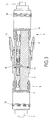
- the two-part, from the plugs according to Figures 1 and 2 composite coupling according to Figure 3 consists of two Cable 1, 2 connected cable connector 3, 4.
- Each of the Both cable plugs are made entirely of polyamide existing injection molded cylindrical housing 5, 6 and a molded one, also made of polyamide Part, the sleeve 7, 8 built.
- the pens are with the Reference numeral 9, the sockets designated 10.
- the connection of the two protected against splash water Cable connector 3, 4 is secured by a lock, which consists of two eyelets 17 and two locking lugs 18 which in the corresponding eyelets can intervene, as shown in FIG 1 is shown.
- a lock which consists of two eyelets 17 and two locking lugs 18 which in the corresponding eyelets can intervene, as shown in FIG 1 is shown.
- the width of the sleeves 17 with their push buttons 19 is about a third of theirs from the Drawings total length.
- Between the sleeve 17 and the push buttons 19 extends a connecting web 20 with which the eyelets and push buttons on the housing 6 are attached. It should be pointed out again that preferably the entire housing with the eyelets 17, Pushbuttons 19 and the connecting web 20 as one piece Plastic injection molded part is made.
Landscapes
- Connector Housings Or Holding Contact Members (AREA)
- Multi-Conductor Connections (AREA)
- Coupling Device And Connection With Printed Circuit (AREA)
- Details Of Connecting Devices For Male And Female Coupling (AREA)
- Communication Cables (AREA)
- Manufacturing Of Electrical Connectors (AREA)
- Connections By Means Of Piercing Elements, Nuts, Or Screws (AREA)
Applications Claiming Priority (2)
| Application Number | Priority Date | Filing Date | Title |
|---|---|---|---|
| DE29619363U DE29619363U1 (de) | 1996-11-07 | 1996-11-07 | Kabelstecker und daraus bestehende zweiteilige Kupplung |
| DE29619363U | 1996-11-07 |
Publications (3)
| Publication Number | Publication Date |
|---|---|
| EP0841723A2 true EP0841723A2 (fr) | 1998-05-13 |
| EP0841723A3 EP0841723A3 (fr) | 1999-02-17 |
| EP0841723B1 EP0841723B1 (fr) | 2003-05-28 |
Family
ID=8031621
Family Applications (1)
| Application Number | Title | Priority Date | Filing Date |
|---|---|---|---|
| EP97118587A Expired - Lifetime EP0841723B1 (fr) | 1996-11-07 | 1997-10-25 | Connecteur de câble et connexion en deux parties comprenant un tel connecteur |
Country Status (3)
| Country | Link |
|---|---|
| EP (1) | EP0841723B1 (fr) |
| AT (1) | ATE241864T1 (fr) |
| DE (2) | DE29619363U1 (fr) |
Cited By (1)
| Publication number | Priority date | Publication date | Assignee | Title |
|---|---|---|---|---|
| EP1396909A1 (fr) | 2002-09-09 | 2004-03-10 | Hirschmann Electronics GmbH & Co. KG | Serre câble |
Families Citing this family (7)
| Publication number | Priority date | Publication date | Assignee | Title |
|---|---|---|---|---|
| DE19710428B4 (de) * | 1997-03-13 | 2006-03-09 | Siteko Kontakttechnik Gmbh | Verfahren zur Herstellung eines Steckverbinders |
| JP3311638B2 (ja) * | 1997-05-22 | 2002-08-05 | 矢崎総業株式会社 | 被覆導体導出部の防水方法 |
| DE10006211C2 (de) * | 2000-02-11 | 2003-11-27 | Robert Virant | Formgebend umspritzte, elektrische und/oder elektronische Komponente und Verfahren zur Herstellung |
| DE10034503C2 (de) * | 2000-07-15 | 2003-01-30 | Lumberg Karl Gmbh & Co | Elektrischer Steckverbinder |
| DE10034502C2 (de) * | 2000-07-15 | 2002-10-31 | Lumberg Karl Gmbh & Co | Elektrischer Steckverbinder |
| DE10330393B4 (de) * | 2003-07-04 | 2005-08-04 | Leonhardy Gmbh | Vorrichtung und Verfahren für einen Steckverbinder |
| ES2983124T3 (es) * | 2015-11-13 | 2024-10-21 | Hirschmann Automotive Gmbh | Proceso de enchufado en dos etapas en conectores de enchufe |
Citations (5)
| Publication number | Priority date | Publication date | Assignee | Title |
|---|---|---|---|---|
| DE2946915A1 (de) | 1979-11-21 | 1981-06-11 | Daut & Rietz KG Fabrik für Elektrofeinmechanik GmbH & Co, 8500 Nürnberg | Steckverbinder |
| US5116236A (en) | 1990-11-05 | 1992-05-26 | Molex Incorporated | Electrical connector with terminal position assurance component |
| DE4115119C2 (fr) | 1991-05-08 | 1993-02-18 | Leopold Kostal Gmbh & Co Kg, 5880 Luedenscheid, De | |
| EP0645847A2 (fr) | 1993-09-27 | 1995-03-29 | Molex Incorporated | Connecteur étanché |
| DE19548069A1 (de) | 1994-12-22 | 1996-07-11 | Kostal Leopold Gmbh & Co Kg | Steckverbinder mit einer Ringdichtung |
Family Cites Families (5)
| Publication number | Priority date | Publication date | Assignee | Title |
|---|---|---|---|---|
| US3816641A (en) * | 1973-05-14 | 1974-06-11 | Viking Industries | Underwater connector and method of making same |
| GB2042826B (en) * | 1979-02-02 | 1983-08-24 | Simplex Ltd | Electrical appliance connector |
| DE3443888C1 (de) * | 1984-12-01 | 1986-05-22 | Leopold Kostal GmbH & Co KG, 5880 Lüdenscheid | Elektrischer Steckverbinder |
| US5462457A (en) * | 1994-09-22 | 1995-10-31 | The Whitaker Corporation | Overmold strain relief and snag prevention feature |
| JP2910609B2 (ja) * | 1995-02-24 | 1999-06-23 | 住友電装株式会社 | コネクタハウジングのロック機構 |
-
1996
- 1996-11-07 DE DE29619363U patent/DE29619363U1/de not_active Expired - Lifetime
-
1997
- 1997-10-25 AT AT97118587T patent/ATE241864T1/de not_active IP Right Cessation
- 1997-10-25 EP EP97118587A patent/EP0841723B1/fr not_active Expired - Lifetime
- 1997-10-25 DE DE59710162T patent/DE59710162D1/de not_active Expired - Lifetime
Patent Citations (5)
| Publication number | Priority date | Publication date | Assignee | Title |
|---|---|---|---|---|
| DE2946915A1 (de) | 1979-11-21 | 1981-06-11 | Daut & Rietz KG Fabrik für Elektrofeinmechanik GmbH & Co, 8500 Nürnberg | Steckverbinder |
| US5116236A (en) | 1990-11-05 | 1992-05-26 | Molex Incorporated | Electrical connector with terminal position assurance component |
| DE4115119C2 (fr) | 1991-05-08 | 1993-02-18 | Leopold Kostal Gmbh & Co Kg, 5880 Luedenscheid, De | |
| EP0645847A2 (fr) | 1993-09-27 | 1995-03-29 | Molex Incorporated | Connecteur étanché |
| DE19548069A1 (de) | 1994-12-22 | 1996-07-11 | Kostal Leopold Gmbh & Co Kg | Steckverbinder mit einer Ringdichtung |
Non-Patent Citations (1)
| Title |
|---|
| "Vom Kleb- und Dichtstsoff zum Formteil", ADHAESION, KLEBEN UND DICHTEN, vol. 37, November 1993 (1993-11-01), pages 35 - 37, XP002945207 |
Cited By (1)
| Publication number | Priority date | Publication date | Assignee | Title |
|---|---|---|---|---|
| EP1396909A1 (fr) | 2002-09-09 | 2004-03-10 | Hirschmann Electronics GmbH & Co. KG | Serre câble |
Also Published As
| Publication number | Publication date |
|---|---|
| DE59710162D1 (de) | 2003-07-03 |
| ATE241864T1 (de) | 2003-06-15 |
| EP0841723B1 (fr) | 2003-05-28 |
| DE29619363U1 (de) | 1997-02-27 |
| EP0841723A3 (fr) | 1999-02-17 |
Similar Documents
| Publication | Publication Date | Title |
|---|---|---|
| DE19751844C2 (de) | Einrichtung zum Anschließen und Verbinden einer Leitung | |
| EP1317025B1 (fr) | Dispositif de connection à forte contrainte pour cable de données, plus particulièrement connecteur RJ-45 | |
| DE102009010492B3 (de) | Kabelordnender Einsatz für Steckverbinder | |
| EP3454427A1 (fr) | Ensemble connecteur kit d'installation et installation électrique | |
| WO2017076781A1 (fr) | Connecteur hybride | |
| DE102012110232B4 (de) | Verbindungsvorrichtung zur Stromübertragung im Kraftfahrzeugbereich | |
| EP3152809A2 (fr) | Appareil électrique | |
| DE2215757A1 (de) | Koaxialsteckverbindung | |
| EP0841723B1 (fr) | Connecteur de câble et connexion en deux parties comprenant un tel connecteur | |
| DE102010034789B3 (de) | Steckverbinder | |
| DE102017004266B4 (de) | Steckverbinder und Steckverbindersystem | |
| DE20318583U1 (de) | Ladesteckverbindersatz mit Adapter | |
| DE102008059000B4 (de) | Elektrisches Steckverbindersystem | |
| DE202007017488U1 (de) | Steckeranordnung | |
| CH697606B1 (de) | Steckbare Kabelkupplung. | |
| EP4699191A1 (fr) | Système de fiches de connexion haute puissance | |
| EP3143320A1 (fr) | Unité de raccordement destinée à un dispositif d'accouplement, en particulier à un raccord multiple | |
| DE10215194A1 (de) | Steckverbindung für den Ausseneinsatz, insbesondere für den elektrichen Anschluss von Solarpanels | |
| DE19737321C2 (de) | Einpolige Laststeckverbinderkombination | |
| DE2206753C3 (de) | Mehrpolige Steckverbindung für die Verdrahtung von Lichtbändern | |
| EP4290707B1 (fr) | Dispositif de connexion | |
| AT410616B (de) | Elektrischer kabelstecker | |
| DE102016000384A1 (de) | Mehrpoliger elektrischer Verbinder | |
| DE102006017983B4 (de) | Elektrische Steckverbindung | |
| EP2511983B1 (fr) | Cosse |
Legal Events
| Date | Code | Title | Description |
|---|---|---|---|
| PUAI | Public reference made under article 153(3) epc to a published international application that has entered the european phase |
Free format text: ORIGINAL CODE: 0009012 |
|
| AK | Designated contracting states |
Kind code of ref document: A2 Designated state(s): AT BE DE DK ES FR GR IT NL PT |
|
| AX | Request for extension of the european patent |
Free format text: AL;LT;LV;RO;SI |
|
| PUAL | Search report despatched |
Free format text: ORIGINAL CODE: 0009013 |
|
| AK | Designated contracting states |
Kind code of ref document: A3 Designated state(s): AT BE CH DE DK ES FI FR GB GR IE IT LI LU MC NL PT SE |
|
| AX | Request for extension of the european patent |
Free format text: AL;LT;LV;RO;SI |
|
| RHK1 | Main classification (correction) |
Ipc: H01R 13/58 |
|
| 17P | Request for examination filed |
Effective date: 19990805 |
|
| 17Q | First examination report despatched |
Effective date: 19990903 |
|
| AKX | Designation fees paid |
Free format text: AT BE DE DK ES FR GR IT NL PT |
|
| TPAD | Observations filed by third parties |
Free format text: ORIGINAL CODE: EPIDOS TIPA |
|
| TPAD | Observations filed by third parties |
Free format text: ORIGINAL CODE: EPIDOS TIPA |
|
| GRAG | Despatch of communication of intention to grant |
Free format text: ORIGINAL CODE: EPIDOS AGRA |
|
| GRAG | Despatch of communication of intention to grant |
Free format text: ORIGINAL CODE: EPIDOS AGRA |
|
| GRAG | Despatch of communication of intention to grant |
Free format text: ORIGINAL CODE: EPIDOS AGRA |
|
| GRAH | Despatch of communication of intention to grant a patent |
Free format text: ORIGINAL CODE: EPIDOS IGRA |
|
| GRAH | Despatch of communication of intention to grant a patent |
Free format text: ORIGINAL CODE: EPIDOS IGRA |
|
| GRAA | (expected) grant |
Free format text: ORIGINAL CODE: 0009210 |
|
| AK | Designated contracting states |
Designated state(s): AT BE DE DK ES FR GR IT NL PT |
|
| PG25 | Lapsed in a contracting state [announced via postgrant information from national office to epo] |
Ref country code: NL Free format text: LAPSE BECAUSE OF FAILURE TO SUBMIT A TRANSLATION OF THE DESCRIPTION OR TO PAY THE FEE WITHIN THE PRESCRIBED TIME-LIMIT Effective date: 20030528 |
|
| REF | Corresponds to: |
Ref document number: 59710162 Country of ref document: DE Date of ref document: 20030703 Kind code of ref document: P |
|
| PG25 | Lapsed in a contracting state [announced via postgrant information from national office to epo] |
Ref country code: PT Free format text: LAPSE BECAUSE OF FAILURE TO SUBMIT A TRANSLATION OF THE DESCRIPTION OR TO PAY THE FEE WITHIN THE PRESCRIBED TIME-LIMIT Effective date: 20030828 Ref country code: GR Free format text: LAPSE BECAUSE OF FAILURE TO SUBMIT A TRANSLATION OF THE DESCRIPTION OR TO PAY THE FEE WITHIN THE PRESCRIBED TIME-LIMIT Effective date: 20030828 Ref country code: DK Free format text: LAPSE BECAUSE OF FAILURE TO SUBMIT A TRANSLATION OF THE DESCRIPTION OR TO PAY THE FEE WITHIN THE PRESCRIBED TIME-LIMIT Effective date: 20030828 |
|
| PG25 | Lapsed in a contracting state [announced via postgrant information from national office to epo] |
Ref country code: ES Free format text: LAPSE BECAUSE OF FAILURE TO SUBMIT A TRANSLATION OF THE DESCRIPTION OR TO PAY THE FEE WITHIN THE PRESCRIBED TIME-LIMIT Effective date: 20030908 |
|
| PG25 | Lapsed in a contracting state [announced via postgrant information from national office to epo] |
Ref country code: AT Free format text: LAPSE BECAUSE OF NON-PAYMENT OF DUE FEES Effective date: 20031025 |
|
| PGFP | Annual fee paid to national office [announced via postgrant information from national office to epo] |
Ref country code: FR Payment date: 20031030 Year of fee payment: 7 |
|
| PG25 | Lapsed in a contracting state [announced via postgrant information from national office to epo] |
Ref country code: BE Free format text: LAPSE BECAUSE OF NON-PAYMENT OF DUE FEES Effective date: 20031031 |
|
| NLV1 | Nl: lapsed or annulled due to failure to fulfill the requirements of art. 29p and 29m of the patents act | ||
| ET | Fr: translation filed | ||
| PLBE | No opposition filed within time limit |
Free format text: ORIGINAL CODE: 0009261 |
|
| STAA | Information on the status of an ep patent application or granted ep patent |
Free format text: STATUS: NO OPPOSITION FILED WITHIN TIME LIMIT |
|
| BERE | Be: lapsed |
Owner name: *SCHON PETER Effective date: 20031031 |
|
| 26N | No opposition filed |
Effective date: 20040302 |
|
| PG25 | Lapsed in a contracting state [announced via postgrant information from national office to epo] |
Ref country code: FR Free format text: LAPSE BECAUSE OF NON-PAYMENT OF DUE FEES Effective date: 20050630 |
|
| REG | Reference to a national code |
Ref country code: FR Ref legal event code: ST |
|
| PG25 | Lapsed in a contracting state [announced via postgrant information from national office to epo] |
Ref country code: IT Free format text: LAPSE BECAUSE OF NON-PAYMENT OF DUE FEES;WARNING: LAPSES OF ITALIAN PATENTS WITH EFFECTIVE DATE BEFORE 2007 MAY HAVE OCCURRED AT ANY TIME BEFORE 2007. THE CORRECT EFFECTIVE DATE MAY BE DIFFERENT FROM THE ONE RECORDED. Effective date: 20051025 |
|
| PGFP | Annual fee paid to national office [announced via postgrant information from national office to epo] |
Ref country code: DE Payment date: 20120102 Year of fee payment: 15 |
|
| PG25 | Lapsed in a contracting state [announced via postgrant information from national office to epo] |
Ref country code: DE Free format text: LAPSE BECAUSE OF NON-PAYMENT OF DUE FEES Effective date: 20130501 |
|
| REG | Reference to a national code |
Ref country code: DE Ref legal event code: R119 Ref document number: 59710162 Country of ref document: DE Effective date: 20130501 |