EP0841735B1 - Verbesserungen an flüssigkeitsgekühlten Generatoren - Google Patents
Verbesserungen an flüssigkeitsgekühlten Generatoren Download PDFInfo
- Publication number
- EP0841735B1 EP0841735B1 EP97402584A EP97402584A EP0841735B1 EP 0841735 B1 EP0841735 B1 EP 0841735B1 EP 97402584 A EP97402584 A EP 97402584A EP 97402584 A EP97402584 A EP 97402584A EP 0841735 B1 EP0841735 B1 EP 0841735B1
- Authority
- EP
- European Patent Office
- Prior art keywords
- passage
- alternator
- designed
- cooling
- vehicle
- Prior art date
- Legal status (The legal status is an assumption and is not a legal conclusion. Google has not performed a legal analysis and makes no representation as to the accuracy of the status listed.)
- Expired - Lifetime
Links
- 238000001816 cooling Methods 0.000 claims description 45
- 239000007788 liquid Substances 0.000 claims description 15
- 238000002485 combustion reaction Methods 0.000 claims description 9
- 238000010438 heat treatment Methods 0.000 description 12
- 239000002826 coolant Substances 0.000 description 6
- 238000009795 derivation Methods 0.000 description 6
- XLYOFNOQVPJJNP-UHFFFAOYSA-N water Substances O XLYOFNOQVPJJNP-UHFFFAOYSA-N 0.000 description 3
- 238000011144 upstream manufacturing Methods 0.000 description 2
- 238000007654 immersion Methods 0.000 description 1
- 238000011084 recovery Methods 0.000 description 1
Images

Classifications
-
- H—ELECTRICITY
- H02—GENERATION; CONVERSION OR DISTRIBUTION OF ELECTRIC POWER
- H02K—DYNAMO-ELECTRIC MACHINES
- H02K5/00—Casings; Enclosures; Supports
- H02K5/04—Casings or enclosures characterised by the shape, form or construction thereof
- H02K5/20—Casings or enclosures characterised by the shape, form or construction thereof with channels or ducts for flow of cooling medium
- H02K5/203—Casings or enclosures characterised by the shape, form or construction thereof with channels or ducts for flow of cooling medium specially adapted for liquids, e.g. cooling jackets
-
- H—ELECTRICITY
- H02—GENERATION; CONVERSION OR DISTRIBUTION OF ELECTRIC POWER
- H02K—DYNAMO-ELECTRIC MACHINES
- H02K5/00—Casings; Enclosures; Supports
- H02K5/04—Casings or enclosures characterised by the shape, form or construction thereof
- H02K5/20—Casings or enclosures characterised by the shape, form or construction thereof with channels or ducts for flow of cooling medium
Definitions
- the present invention relates to alternators of the liquid cooled type. It relates to also rear bearings for such alternators, as well as engine cooling circuits to combustion of a motor vehicle.
- the alternator Apart from air cooling, another solution is to integrate the alternator into the loop engine cooling, the body of the alternator comprising at least one cooling passage in which circulates the liquid of the circuit of cooling said engine.
- this derivation is carried out by a pipe mounted outside the alternator, which poses congestion problems.
- the invention proposes to integrate this derivation in the body of the alternator.
- the invention proposes a alternator for a vehicle, especially a motor vehicle, comprising a body in which a stator is mounted, as well as a rotor integral with a shaft rotatably mounted on bearings said body, the body having at least one internal passage for the circulation of a liquid intended for cooling said alternator, said passage being intended for be connected to a cooling circuit of a motor to combustion of a motor vehicle that passes through an air-liquid exchanger for heating the passenger compartment of the vehicle, said alternator being characterized in that his body has between the entrance and the exit of the passage internal cooling a second internal passage of the type intended for derive some of the flow required to the air-liquid exchanger.
- the body has a connecting tail in which are formed an inlet duct and an outlet duct intended to connect the cooling passage to the circuit of the combustion engine of the vehicle, the bypass passage being formed in the tail of connection between said input conauit and said conduit Release.
- bypass passage extends in the thickness of a flask that presents one of the bearings of the body.
- bypass passage extends substantially on said flange in a ring.
- the body comprises a rear bearing receiving the stator and the rotor, as well as a front bearing that closes the rear bearing, the passage of cooling and bypass passage being spared on the rear bearing.
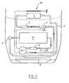
- the cooling circuit C illustrated on the FIG. 1 serves to cool both an engine block M and a alternator ALT driven by this engine block M. He also contributes to the heating of the passenger compartment of the vehicle automobile, the coolant supplying output of engine block M and alternator ALT one air-liquid exchanger or air heater 1.
- the block motor M is upstream of the alternator ALT, which is it even upstream of the heater 1, the circuit of cooling C being closed between the heater 1 and the motor block M via a pump P which forces the circulation of the coolant in said circuit.
- the coolant is water.
- a cooling radiator R is provided for the front of the vehicle hood, to cool the cooling thanks to a flow of air created by the speed of the vehicle or by a motor-driven fan at the level of said radiator.
- the heat energy collected during the cooling of engine block M and alternator ALT by the coolant is used for the cockpit heating.
- the ALT alternator contributes to the engine block temperature.
- it can be provided in the cooling circuit portion C integrated into the alternator of the heating elements by effect Joule to accelerate the temperature rise of the coolant when starting the vehicle.
- These heating elements are for example powered by the current output of the alternator ALT.
- FIG. it is arranged between on the one hand the motor unit M and the alternator ALT and on the other hand the heater 1 a immersion heater 2 powered by the alternator ALT.
- the heater 1 is for example arranged, with other heating means, such as a resistor Re electric with positive temperature coefficient powered by the alternator ALT which dissipates by effect joule, on the right of the exchange zone between the cooling and cabin air in an area heating feet to the front of the vehicle.
- other heating means such as a resistor Re electric with positive temperature coefficient powered by the alternator ALT which dissipates by effect joule, on the right of the exchange zone between the cooling and cabin air in an area heating feet to the front of the vehicle.
- Flow controllers 3 and 4 are provided in input of the portion of the cooling circuit C which is integrated into the alternator ALT, as well as 1. These regulators 3 and 4 allow optimize flows on the one hand for cooling of alternator ALT and secondly for heating by the heater 2
- the flow required through the heater 1 being more important than the flow through the alternator ALT, it is provided on the cooling circuit C a derivation D between the input and the output of the portion said circuit in the body of the alternator ALT.
- this derivation D is itself integrated into the body of the alternator ALT.
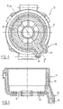
- FIGS. 2 and 3 show a first possible embodiment for this derivation.
- This rear bearing 10 comprises a body 11 of shape mainly cylindrical, and a flange 12 which close this body 11 at one of its ends.
- This level rear 10 defines with a front bearing which is intended for close it and that has not been represented in the figures, the body or housing of the alternator. Both levels carry the alternator shaft.
- the stator of the alternator is fixed inside the rear bearing 10, while the rotor is secured in rotation with the shaft of the alternator.
- the main cooling circuit C of this bearing 10 is constituted by a passage 13 (FIG. 3) cylindrical ring formed in the thickness of the body 11, on substantially all the periphery of it without being closed on itself.
- This passage 13 is connected to the circuit of C cooling of the internal combustion engine through two tubular conduits 14 and 15 juxtaposed - one input, the other output - spared in a connecting tail 16 which extends to the side of an area of the body 11, in the vicinity of the flange 12, and beyond said flange 12.
- the branch circuit D is in this variant a tubular passage that is formed in the tail of connection 16 of the bearing 10 and which connects the sleeves input and output 14 and 15, at the input and output of the passage 13 of the alternator cooling.
- the branch circuit D is a conduit tubular small diameter which is formed in the thickness of the rear bearing 10 and which extends thereon according to a ring centered on the bearing axis, between the inlet duct and the outlet duct 14 and 15 of the connecting tail 16.
- This configuration is particularly advantageous.
- the annular bypass passage D formed on the flange 12 contributes to the cooling of electronic elements mounted on the flange 12, by example to the cooling of the diodes of the bridge of recovery of the alternator ALT or at cooling of the control electronics of the elements integrated heater ALT alternator.
Landscapes
- Engineering & Computer Science (AREA)
- Power Engineering (AREA)
- Motor Or Generator Cooling System (AREA)
Claims (10)
- Wechselstromgenerator für Fahrzeuge, insbesondere Kraftfahrzeuge, mit einem Körper (10), in dem ein Ständer sowie ein Läufer angebracht sind, der fest mit einer Welle verbunden ist, die drehbar auf Lagerschilden gelagert ist, die der besagte Körper (10) aufweist, wobei der Körper (10) wenigstens einen inneren Durchlaß (13) für die Zirkulation einer Flüssigkeit enthält, die zur Kühlung des besagten Wechselstromgenerators (ALT) bestimmt ist, wobei der besagte Durchlaß (13) dazu bestimmt ist, mit einem Kühlkreislauf (C) eines Verbrennungsmotors (M) eines Kraftfahrzeugs verbunden zu werden, der außerdem durch einen Luft-Flüssigkeits-Wärmetauscher (1) hindurchgeht, der dazu bestimmt ist, den Fahrgastraum des Fahrzeugs zu heizen, wobei der besagte Wechselstromgenerator dadurch gekennzeichnet ist, daß sein Körper (10) zwischen dem Einlaß und dem Auslaß (14, 15) des inneren Kühldurchlasses (13) einen zweiten inneren Durchlaß (D) enthält, der dazu bestimmt ist, einen Teil des Durchsatzes, der für den Luft-Flüssigkeits-Wärmetauscher (1) erforderlich ist, abzuzweigen.
- Wechselstromgenerator nach Anspruch 1, dadurch gekennzeichnet, daß der Körper (14) ein Anschlußendstück (16) umfaßt, in dem ein Einlaßkanal und ein Auslaßkanal (14, 15) angeordnet sind, die dazu bestimmt sind, den Kühldurchlaß (13) mit dem Kühlkreislauf (C) des Verbrennungsmotors (M) des Fahrzeugs zu verbinden, wobei der Abzweigdurchlaß (D) in dem Anschlußendstück (16) zwischen dem besagten Einlaßkanal und dem besagten Auslaßkanal (14, 15) angeordnet ist.
- Wechselstromgenerator nach Anspruch 1, dadurch gekennzeichnet, daß sich der Abzweigdurchlaß (D) in der Dicke eines Flansches erstreckt, den einer (10) der Lagerschilde des Körpers aufweist.
- Wechselstromgenerator nach Anspruch 3, dadurch gekennzeichnet, daß sich der Abzweigdurchlaß (D) in etwa auf dem besagten Flansch (12) entlang einem Ring erstreckt.
- Wechselstromgenerator nach einem der vorangehenden Ansprüche, dadurch gekennzeichnet, daß der Körper einen hinteren Lagerschild (10), der den Ständer und den Läufer aufnimmt, sowie einen vorderen Lagerschild umfaßt, der den hinteren Lagerschild verschließt, wobei der Kühldurchlaß (13) und der Abzweigdurchlaß (D) an dem hinteren Lagerschild (10) angeordnet sind.
- Hinterer Lagerschild für einen flüssigkeitsgekühlten Wechselstromgenerator mit einem Körper (11), der dazu bestimmt ist, den Ständer und den Läufer des Wechselstromgenerators aufzunehmen, und mit einem Flansch (12) der den besagten Körper an einem seiner Enden verschließt, wobei der Körper wenigstens einen inneren Durchlaß (13) für die Zirkulation einer Flüssigkeit enthält, die zur Kühlung des besagten Wechselstromgenerators bestimmt ist, wobei der besagte Durchlaß (13) dazu bestimmt ist, mit einem Kühlkreislauf (C) eines Verbrennungsmotors (M) eines Kraftfahrzeugs verbunden zu werden, der außerdem einen Luft-Flüssigkeits-Wärmetauscher (1) umfaßt, der dazu bestimmt ist, den Fahrgastraum des Fahrzeugs zu heizen, wobei der besagte Lagerschild (10)
dadurch gekennzeichnet ist, daß er zwischen dem Einlaß und dem Auslaß (14, 15) des inneren Kühldurchlasses (13) einen zweiten inneren Durchlaß (C) enthält, der dazu bestimmt ist, einen Teil des Durchsatzes, der für den Luft-Flüssigkeits-Wärmetauscher (1) erforderlich ist, abzuzweigen. - Lagerschild nach Anspruch 6, dadurch gekennzeichnet, daß er ein Anschlußendstück (16) enthält, in dem ein Einlaßkanal und ein Auslaßkanal (14, 15) angeordnet sind, die dazu bestimmt sind, den Kühldurchlaß (13) mit dem Kühlkreislauf (C) des Verbrennungsmotors (M) des Fahrzeugs zu verbinden, wobei der Abzweigdurchlaß (D) in dem Anschlußendstück (16) zwischen dem besagten Einlaßkanal und dem besagten Auslaßkanal (14, 15) angeordnet ist.
- Lagerschild nach Anspruch 6, dadurch gekennzeichnet, daß sich der Abzweigdurchlaß (D) in der Dicke des Flansches (12) erstreckt.
- Lagerschild nach Anspruch 8, dadurch gekennzeichnet, daß sich der Abzweigdurchlaß (D) in etwa auf dem besagten Flansch (12) entlang einem Ring erstreckt.
- Kühlkreislauf (C) eines Verbrennungsmotors (M) eines Kraftfahrzeugs, der außerdem durch einen Luft-Flüssigkeits-Wärmetauscher (1) hindurchgeht, der dazu bestimmt ist, den Fahrgastraum des Fahrzeugs zu heizen, dadurch gekennzeichnet, daß er mit dem Einlaß und mit dem Auslaß (14, 15) eines Kühldurchlasses (13) und eines Abzweigdurchlasses (D) eines Wechselstromgenerators (ALT) nach einem der Ansprüche 1 bis 5 verbunden ist.
Applications Claiming Priority (2)
| Application Number | Priority Date | Filing Date | Title |
|---|---|---|---|
| FR9613329A FR2755314B1 (fr) | 1996-10-31 | 1996-10-31 | Perfectionnements aux alternateurs du type refroidi par liquide |
| FR9613329 | 1996-10-31 |
Publications (2)
| Publication Number | Publication Date |
|---|---|
| EP0841735A1 EP0841735A1 (de) | 1998-05-13 |
| EP0841735B1 true EP0841735B1 (de) | 2005-02-16 |
Family
ID=9497234
Family Applications (1)
| Application Number | Title | Priority Date | Filing Date |
|---|---|---|---|
| EP97402584A Expired - Lifetime EP0841735B1 (de) | 1996-10-31 | 1997-10-30 | Verbesserungen an flüssigkeitsgekühlten Generatoren |
Country Status (3)
| Country | Link |
|---|---|
| EP (1) | EP0841735B1 (de) |
| DE (1) | DE69732512T2 (de) |
| FR (1) | FR2755314B1 (de) |
Families Citing this family (3)
| Publication number | Priority date | Publication date | Assignee | Title |
|---|---|---|---|---|
| DE10024665A1 (de) * | 2000-05-18 | 2001-11-22 | Bosch Gmbh Robert | Abdeckkappe, insbesonere für Generatoren |
| DE10043059A1 (de) | 2000-09-01 | 2002-03-28 | Bosch Gmbh Robert | Elektrische Maschine |
| DE10134678A1 (de) | 2001-07-20 | 2003-02-06 | Bosch Gmbh Robert | Vorrichtung zum Kühlen und Heizen eines Kraftfahrzeuges |
Family Cites Families (3)
| Publication number | Priority date | Publication date | Assignee | Title |
|---|---|---|---|---|
| KR910001521B1 (ko) * | 1987-03-23 | 1991-03-15 | 미쓰비시전기 주식회사 | 차량발전기와 기관용 시동전동기의 냉각장치 |
| JPH0810974B2 (ja) * | 1988-04-25 | 1996-01-31 | 三菱電機株式会社 | 車両用交流発電機 |
| FR2717640B1 (fr) * | 1994-03-18 | 1996-04-26 | Valeo Equip Electr Moteur | Alternateur de véhicule automobile comportant une chambre de refroidissement intégrée à l'enveloppe du stator. |
-
1996
- 1996-10-31 FR FR9613329A patent/FR2755314B1/fr not_active Expired - Lifetime
-
1997
- 1997-10-30 DE DE69732512T patent/DE69732512T2/de not_active Expired - Fee Related
- 1997-10-30 EP EP97402584A patent/EP0841735B1/de not_active Expired - Lifetime
Also Published As
| Publication number | Publication date |
|---|---|
| DE69732512T2 (de) | 2006-02-16 |
| FR2755314B1 (fr) | 1999-01-15 |
| DE69732512D1 (de) | 2005-03-24 |
| EP0841735A1 (de) | 1998-05-13 |
| FR2755314A1 (fr) | 1998-04-30 |
Similar Documents
| Publication | Publication Date | Title |
|---|---|---|
| EP3953199B1 (de) | Kühlungs- und schmierungseinrichtung einer elektrischen antriebsbaugruppe eines elektro- oder hybrid-fahrzeugs | |
| CA2148019C (en) | Pre-heater for liquid-cooled internal combustion engine | |
| FR3042658A1 (fr) | Dispositif de gestion thermique d'un groupe motopropulseur electrique. | |
| FR2827359A1 (fr) | Vanne de commande pour un circuit de refroidissement d'un moteur thermique de vehicule automobile | |
| FR2809451A1 (fr) | Moteur thermique a circuit de refroidissement et echangeur de chaleur de chauffage, relie a celui-ci | |
| FR2748428A1 (fr) | Systeme de refroidissement pour vehicule a propulsion hybride | |
| EP2112347B1 (de) | Kühlmittelkreislauf eines Motors | |
| FR2690112A1 (fr) | Dispositif de chauffage-ventilation de l'habitacle d'un véhicule automobile propulsé par un moteur à faibles rejets thermiques. | |
| EP1197644B1 (de) | System und Verfahren zur Kühlung eines Hybridfahrzeugs | |
| FR2519694A1 (fr) | Circuit hydraulique economique pour le refroidissement d'un moteur a combustion interne de vehicule automobile | |
| EP0841735A1 (de) | Verbesserungen an flüssigkeitsgekühlten Generatoren | |
| EP4186149B1 (de) | Elektromotor und antriebssystem zur wärmeübertragung | |
| WO2008029029A1 (fr) | Dispositif de distribution de liquide de refroidissement dans un moteur de vehicule automobile | |
| FR2746351A1 (fr) | Appareil de chauffage pour vehicule | |
| FR2817287A1 (fr) | Dispositif pour la regulation de temperature d'un moteur a combustion interne | |
| FR2830215A1 (fr) | Dispositif de refroidissement pour une unite motrice | |
| EP0850791B1 (de) | Heizungssystem für den Fahrgastraum eines Kraftfahrzeuges mit Dieselmotor mit Direkteinspritzung | |
| FR2891205A1 (fr) | Machine a moteur electrique de deplacement, moteur electrique de pompe d'un systeme hydraulque et refroidissement par liquide | |
| EP4069956B1 (de) | Wärmeübertragungskreislauf für einen antriebsstrang | |
| FR2881587A1 (fr) | Dispositif permettant le refroidissement d'une machine electrique tournante par circulation d'un fluide de refroidissement | |
| FR2815402A1 (fr) | Dispositif, systeme et procede de refroidissement d'un fluide caloporteur | |
| FR2537509A1 (fr) | Dispositif de chauffage pour vehicule automobile a propulsion electrique | |
| WO2017203116A1 (fr) | Groupe motopropulseur d'un vehicule | |
| FR3093957A1 (fr) | Dispositif de chauffage de fluide pour vehicule automobile | |
| EP0670414A1 (de) | Kühlungsanlage für eine Brennkraftmaschine |
Legal Events
| Date | Code | Title | Description |
|---|---|---|---|
| PUAI | Public reference made under article 153(3) epc to a published international application that has entered the european phase |
Free format text: ORIGINAL CODE: 0009012 |
|
| AK | Designated contracting states |
Kind code of ref document: A1 Designated state(s): DE ES GB IT |
|
| 17P | Request for examination filed |
Effective date: 19981102 |
|
| AKX | Designation fees paid |
Free format text: DE ES GB IT |
|
| RBV | Designated contracting states (corrected) |
Designated state(s): DE ES GB IT |
|
| 17Q | First examination report despatched |
Effective date: 20040329 |
|
| GRAP | Despatch of communication of intention to grant a patent |
Free format text: ORIGINAL CODE: EPIDOSNIGR1 |
|
| GRAS | Grant fee paid |
Free format text: ORIGINAL CODE: EPIDOSNIGR3 |
|
| GRAA | (expected) grant |
Free format text: ORIGINAL CODE: 0009210 |
|
| AK | Designated contracting states |
Kind code of ref document: B1 Designated state(s): DE ES GB IT |
|
| PG25 | Lapsed in a contracting state [announced via postgrant information from national office to epo] |
Ref country code: GB Free format text: LAPSE BECAUSE OF FAILURE TO SUBMIT A TRANSLATION OF THE DESCRIPTION OR TO PAY THE FEE WITHIN THE PRESCRIBED TIME-LIMIT Effective date: 20050216 |
|
| REG | Reference to a national code |
Ref country code: GB Ref legal event code: FG4D Free format text: NOT ENGLISH |
|
| REF | Corresponds to: |
Ref document number: 69732512 Country of ref document: DE Date of ref document: 20050324 Kind code of ref document: P |
|
| PG25 | Lapsed in a contracting state [announced via postgrant information from national office to epo] |
Ref country code: ES Free format text: LAPSE BECAUSE OF FAILURE TO SUBMIT A TRANSLATION OF THE DESCRIPTION OR TO PAY THE FEE WITHIN THE PRESCRIBED TIME-LIMIT Effective date: 20050527 |
|
| GBV | Gb: ep patent (uk) treated as always having been void in accordance with gb section 77(7)/1977 [no translation filed] |
Effective date: 20050216 |
|
| PLBE | No opposition filed within time limit |
Free format text: ORIGINAL CODE: 0009261 |
|
| STAA | Information on the status of an ep patent application or granted ep patent |
Free format text: STATUS: NO OPPOSITION FILED WITHIN TIME LIMIT |
|
| 26N | No opposition filed |
Effective date: 20051117 |
|
| PGFP | Annual fee paid to national office [announced via postgrant information from national office to epo] |
Ref country code: DE Payment date: 20081010 Year of fee payment: 12 |
|
| PGFP | Annual fee paid to national office [announced via postgrant information from national office to epo] |
Ref country code: IT Payment date: 20081018 Year of fee payment: 12 |
|
| PG25 | Lapsed in a contracting state [announced via postgrant information from national office to epo] |
Ref country code: DE Free format text: LAPSE BECAUSE OF NON-PAYMENT OF DUE FEES Effective date: 20100501 |
|
| PG25 | Lapsed in a contracting state [announced via postgrant information from national office to epo] |
Ref country code: IT Free format text: LAPSE BECAUSE OF NON-PAYMENT OF DUE FEES Effective date: 20091030 |