EP0842774A2 - Dispositif pour perforer, poinçonner, couper, canneler, imprimer des enveloppes ou vernir à façon avec des presses à imprimer - Google Patents
Dispositif pour perforer, poinçonner, couper, canneler, imprimer des enveloppes ou vernir à façon avec des presses à imprimer Download PDFInfo
- Publication number
- EP0842774A2 EP0842774A2 EP97810776A EP97810776A EP0842774A2 EP 0842774 A2 EP0842774 A2 EP 0842774A2 EP 97810776 A EP97810776 A EP 97810776A EP 97810776 A EP97810776 A EP 97810776A EP 0842774 A2 EP0842774 A2 EP 0842774A2
- Authority
- EP
- European Patent Office
- Prior art keywords
- cylinder
- cutting
- rubber blanket
- foil
- printing
- Prior art date
- Legal status (The legal status is an assumption and is not a legal conclusion. Google has not performed a legal analysis and makes no representation as to the accuracy of the status listed.)
- Granted
Links
- 239000011888 foil Substances 0.000 claims abstract description 80
- 239000011248 coating agent Substances 0.000 claims description 22
- 238000000576 coating method Methods 0.000 claims description 22
- 229910052751 metal Inorganic materials 0.000 claims description 9
- 239000002184 metal Substances 0.000 claims description 9
- 229920002994 synthetic fiber Polymers 0.000 claims description 7
- 239000004411 aluminium Substances 0.000 claims description 4
- 229910052782 aluminium Inorganic materials 0.000 claims description 4
- XAGFODPZIPBFFR-UHFFFAOYSA-N aluminium Chemical compound [Al] XAGFODPZIPBFFR-UHFFFAOYSA-N 0.000 claims description 4
- 239000002966 varnish Substances 0.000 claims description 4
- 229910001220 stainless steel Inorganic materials 0.000 claims description 2
- 150000001875 compounds Chemical class 0.000 claims 2
- 230000000149 penetrating effect Effects 0.000 claims 1
- 238000004080 punching Methods 0.000 abstract description 19
- 239000000123 paper Substances 0.000 description 7
- 229910000831 Steel Inorganic materials 0.000 description 6
- 239000010959 steel Substances 0.000 description 6
- 239000012790 adhesive layer Substances 0.000 description 2
- 239000002390 adhesive tape Substances 0.000 description 2
- 239000010410 layer Substances 0.000 description 2
- 238000013016 damping Methods 0.000 description 1
- 230000007812 deficiency Effects 0.000 description 1
- 230000001419 dependent effect Effects 0.000 description 1
- 238000011835 investigation Methods 0.000 description 1
- 238000000034 method Methods 0.000 description 1
- 238000012986 modification Methods 0.000 description 1
- 230000004048 modification Effects 0.000 description 1
- 230000001681 protective effect Effects 0.000 description 1
Images


Classifications
-
- B—PERFORMING OPERATIONS; TRANSPORTING
- B41—PRINTING; LINING MACHINES; TYPEWRITERS; STAMPS
- B41N—PRINTING PLATES OR FOILS; MATERIALS FOR SURFACES USED IN PRINTING MACHINES FOR PRINTING, INKING, DAMPING, OR THE LIKE; PREPARING SUCH SURFACES FOR USE AND CONSERVING THEM
- B41N6/00—Mounting boards; Sleeves Make-ready devices, e.g. underlays, overlays; Attaching by chemical means, e.g. vulcanising
-
- B—PERFORMING OPERATIONS; TRANSPORTING
- B26—HAND CUTTING TOOLS; CUTTING; SEVERING
- B26D—CUTTING; DETAILS COMMON TO MACHINES FOR PERFORATING, PUNCHING, CUTTING-OUT, STAMPING-OUT OR SEVERING
- B26D7/00—Details of apparatus for cutting, cutting-out, stamping-out, punching, perforating, or severing by means other than cutting
- B26D7/26—Means for mounting or adjusting the cutting member; Means for adjusting the stroke of the cutting member
- B26D7/2614—Means for mounting the cutting member
-
- B—PERFORMING OPERATIONS; TRANSPORTING
- B41—PRINTING; LINING MACHINES; TYPEWRITERS; STAMPS
- B41F—PRINTING MACHINES OR PRESSES
- B41F19/00—Apparatus or machines for carrying out printing operations combined with other operations
-
- B—PERFORMING OPERATIONS; TRANSPORTING
- B41—PRINTING; LINING MACHINES; TYPEWRITERS; STAMPS
- B41F—PRINTING MACHINES OR PRESSES
- B41F19/00—Apparatus or machines for carrying out printing operations combined with other operations
- B41F19/008—Apparatus or machines for carrying out printing operations combined with other operations with means for stamping or cutting out
-
- B—PERFORMING OPERATIONS; TRANSPORTING
- B41—PRINTING; LINING MACHINES; TYPEWRITERS; STAMPS
- B41F—PRINTING MACHINES OR PRESSES
- B41F23/00—Devices for treating the surfaces of sheets, webs, or other articles in connection with printing
- B41F23/08—Print finishing devices, e.g. for glossing prints
-
- B—PERFORMING OPERATIONS; TRANSPORTING
- B41—PRINTING; LINING MACHINES; TYPEWRITERS; STAMPS
- B41F—PRINTING MACHINES OR PRESSES
- B41F30/00—Devices for attaching coverings or make-ready devices; Guiding devices for coverings
- B41F30/04—Devices for attaching coverings or make-ready devices; Guiding devices for coverings attaching to transfer cylinders
-
- B—PERFORMING OPERATIONS; TRANSPORTING
- B41—PRINTING; LINING MACHINES; TYPEWRITERS; STAMPS
- B41G—APPARATUS FOR BRONZE PRINTING, LINE PRINTING, OR FOR BORDERING OR EDGING SHEETS OR LIKE ARTICLES; AUXILIARY FOR PERFORATING IN CONJUNCTION WITH PRINTING
- B41G7/00—Auxiliary perforating apparatus associated with printing devices
-
- B—PERFORMING OPERATIONS; TRANSPORTING
- B26—HAND CUTTING TOOLS; CUTTING; SEVERING
- B26D—CUTTING; DETAILS COMMON TO MACHINES FOR PERFORATING, PUNCHING, CUTTING-OUT, STAMPING-OUT OR SEVERING
- B26D7/00—Details of apparatus for cutting, cutting-out, stamping-out, punching, perforating, or severing by means other than cutting
- B26D7/26—Means for mounting or adjusting the cutting member; Means for adjusting the stroke of the cutting member
- B26D2007/2607—Means for mounting or adjusting the cutting member; Means for adjusting the stroke of the cutting member for mounting die cutters
Definitions
- the present invention relates to a device for perforating, die-cutting, cutting or creasing at printing machines according to the introduction of independent claim 1.
- the invention relates also to the use of the inventive device for envelope printing or spot varnishing.
- a counter-pressure device for effectuating perforations and/or punching at offset sheet printing machines is known from the US-A-5 623 874 of the same applicant.
- that known device it is particularly provided for to replace the rubber blanket by a hard foil which can be mounted by a fixing means to the rubber blanket cylinder of a printing unit or to the forme roller of a coating unit.
- the use of a hard foil instead of the rubber blanket resulted in a significant improvement with respect to the then known state of the art, particularly by allowing very precise punching and perforating and an increase in the passing rates in perforating. It has, however, proved that the use of such known device is not recommended in endless printing machines.
- a coating unit can either be used for coating or for punching, creasing or perforating.
- the circumference of the coating forme roller is equipped with a punching sheet steel and the circumference of the printing cylinder with a counter-punching sheet steel or vice-versa, in such a way that the coating forme roller is equipped with a counter-punching sheet steel and the printing cylinder with one or several punching sheets steel.
- the device is on one side limited to the use in a coating unit and on the other side neither the punching sheet steel nor the counter-punching sheet steel are described more in detail.
- the device for envelope printing or varnishing comprises is defined in the independent claims 8, 9 and 10. Further advantages and embodiments are defined in the dependent claims.
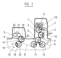
- Figure 1 shows schematically one of optionally several printing units in a offset sheet printing machine with a plate cylinder 1, an impression cylinder 2 and a rubber blanket cylinder 3 disposed in-between, on which a supporting foil 4 is mounted instead of a rubber blanket.
- a conventional rubber blanket is mounted on the rubber blanket cylinder 3.
- both, the rubber blanket cylinder 3 and the impression cylinder 2 are shown with equal diameters.
- the means according to the present invention can, however, also be used in printing or coating units presenting impression cylinders whose diameters are twice the diameters of the rubber blanket cylinder and the forme cylinder respectively.
- the perforation rule 5 is mounted on the supporting foil 4 which itself is affixed to the rubber blanket cylinder 3, usually by a two side adhesive tape, whereby the teeth of the perforation rule 5 are directed towards the impression cylinder 2 in order to perforate the paper running in-between these two cylinders.
- adequate means e.g. die-cutting forms, cutting forms or creasing rules respectively, are mounted.
- this includes all possible means for perforating, die-cutting, cutting and creasing.
- in place of one single perforation rule there may be used several ones.
- the impression cylinder 2 would be sufficient as a backpressure means. However, it is recommendable to protect its surface by a protection foil 22 made of metal or synthetic material.
- the protection foil 22 can be affixed by means of a two side adhesive tape. This combination results in a better and more precise perforation or punching of the paper and furthermore allows to maintain the normal printing speed of offset sheet printing or endless printing machines, such that printing, and perforating, die-cutting, cutting or creasing can be effectuated at the same speed.
- Figure 1 one recognises also an inking system 6 with different inking rollers which transfer the printing ink onto the plate cylinder 1, and a damping system 7.
- the paper sheet 8 arrives from the intermediate drum 9 to a first feed drum 10, from where it continues towards the impression cylinder 2 and further towards the second feed drum 11, from where the paper sheet 8 may be transferred to a further drum, and if provided for, to a further inking system or a coating unit 19.
- a further inking system or a coating unit correspondingly, but without the coating unit, this is also true for an endless printing machine.
- the plate cylinder 1, the impression cylinder 2 and the rubber blanket cylinder 3 are represented on a larger scale and in a sectional view.
- the plate cylinder 1 with the printing plate affixed to it is well known in the state of the art and differs in its constructive details from one type of printing machine to another.
- the impression cylinder 2 is equipped with a protection foil 22, to protect its surface.
- the supporting foil 4 onto which a perforation rule 5 is affixed, if perforating is to be effectuated.
- the perforation rule 5 may be fixed lengthwise or crosswise.
- a coating unit 19 is to be used for perforating, die-cutting, cutting or creasing, on one of its cylinders, the forme cylinder 17, the supporting foil 4 is mounted onto which the perforation rule or forme 5 is affixed.
- impression cylinder 18, the protection foil 22 is mounted on the other cylinder.
- Both cylinders 17 and 18 are provided with similar fixing means 16 for the parts to be mounted onto them, including rails and strips 13, as the afore mentioned cylinders.
- a metering roller 20 and a coating forme roller 21 which of course are not in contact with the forme cylinder 17 during perforating, punching and creasing. Underneath the coating forme roller 21 a coat reception basin is traced.
- a conventional rubber blanket is mounted on the rubber blanket cylinder 3 and the perforation rule or form 5 is taken off.
- the thickness of the layer(s) mounted on the rubber blanket cylinder 3 are standardised in such a way that a defined distance between the rubber blanket cylinder 3 and the impression cylinder 2 co-operating with same is achieved.
- the supporting foil 4 has to have the same thickness as the rubber blanket, whereby the thickness of the perforation rule or forme or the sheet metal are to be taken in account. The same applies equally for the coating module 19.
- a thin metal foil having a thickness of 0.3 mm for example is used.
- an underlying blanket 15 of 1.65 mm thickness is spread under the foil.
- This underlying blanket 15 may have a variable stiffness, adapted to the intended use, and e.g. be made from one or several press board plates. It may be fastened on one side only or on both sides, or even be affixed to the foil.
- the inner underlying blanket 15 of the supporting foil 4 is an independent unit, formed, seen from the side of the rubber blanket cylinder 3, of a combination of at least one calibrated cardboard sheet 14A, having a thickness of between 0.30 to 0.40 mm, and thin aluminium sheets 14B of e.g. 0.30 mm thickness.
- This unit is at least at one of its sides fastened together by rivets 14C.
- the first aluminium sheet, seen from the side of the cardboard sheet, is provided with an edge 14D hooked into the front side of the cylinder gap of the rubber blanket cylinder 3, to position the underlying blanket 15.
- the total thickness of the layers on the rubber blanket cylinder 3 can easily be adjusted to the needs of different types of printing machines, thus avoiding that the printer uses a wrong total thickness.
- the underlying blanket 15 is simply hooked into the front edge of the cylinder gap and the foil 24 fixed with strips onto the fixing means.
- top foil 24 is affixed to two opposite strips 13, which are glued or riveted to it.
- the supporting foil 4 is provided with edges 23 on both of its ends, which edges penetrate into corresponding grooves 25 at the strips 13.
- the foil 24 may be made of a metal sheet, e.g. chromium steel or any other suitable metal or from synthetic material.
- the foil In order to protect the surface of the foil it may be convenient to mount on its top side a relatively hard cover foil, for example of synthetic material, which can be replaced by a new one if necessary.
- cover foil for example of synthetic material
- the total thickness of the supporting foil must correspond to the thickness of the conventional rubber blanket used in a corresponding application.
- the strips 13 correspond to those used with the rubber blanket, thus making it possible to use the same or a similar fixing means 16 on the rubber blanket cylinder 3.
- the supporting foil for perforating together, if necessary, with the underlying blanket and/or the cover foil, no modification of the printing or coating unit is necessary, compared to the use of an usual rubber blanket.
- a further advantage in using the foil 4 is that the paper sheets are not deformed during perforating or punching. Therefore, the entire stack can be piled up in the same manner as before the perforation or punching. Its transportation is thus considerably facilitated, in contrast to the strongly deformed sheets after perforating with a rubber blanket. Therefore, it is also possible to use foil 4 for punching of different patterns, e.g. address areas or the like.
- Figure 4 discloses a further advantageous use of the supporting foil, the use of it for printing envelopes.
- Envelopes have one or two flaps as closure means causing uneven parts, causing folds and the like. The same applies to windows in the envelopes. All these elements cause difficulties for the printing of the envelopes.
- the arrangement of Figure 4 enables a smooth and good quality printing of envelopes.
- Figure 4 shows the impression cylinder 2 and the rubber blanket cylinder 3, on which the supporting foil 4 comprising top foil 24 is fastened as in the previous embodiments.
- top foil 24 is a sheet metal foil.
- a blanket pad 26 is fastened, the pad having a self-adhesive layer for good adherence.
- the rubber blanket pad 26 has only the size of the field to be printed, is inked like an usual rubber blanket for printing, and is fastened on the supporting foil at the spot corresponding to the field where the envelope is to be printed.
- the alignment of the pad is assisted by a coordinate paper fixed on the top foil.
- the use of the inventive set of supporting foil 4 with the foil 24 enables to print only at the field foreseen for it and avoids the use of a rubber blanket covering the whole rubber blanket cylinder and thus also the folds and unevennesses of an envelope. It is evident that the total thickness of the supporting foil 4 with top foil 24 and pad 26 must be the same as the conventionally used rubber blanket. This is effectuated, as described above, by reducing the thickness of the supporting foil set, e.g. of inner underlying blanket 15.
- the same set up with the supporting foil 4 comprising the top foil 24 and one rubber blanket pad or several pads can be used for varnishing at one spot, resp. several spots.
- the spot or spots where the varnish has to be applied has to be projected on the rubber blanket sheet, the rubber blanket is then removed and the space on the rubber blanket where the varnish is not to be applied is subsequently cut out and the rubber blanked with the holes replaced.
- the rubber blanket pad or pads with a self-adhesive layer can be cut in the size of the spot to be varnished and, since the top foil 24 has a coordinate paper on its surface, the pad(s) can be simply applied upon, without having to remove and replace the supporting foil. This procedure simplifies significantly the spotwise varnishing. It is also possible to prepare the supporting foil with the pad or pads and simply fasten it if varnishing is to be accomplished.
- spot varnishing can be effectuated as well with the printing unit as with the coating unit, in the latter the supporting foil with the varnishing pads being mounted on the forme cylinder. It is further appreciated that envelope printing as well as spot varnishing is effectuated without protective foil 22 on the impression cylinder.
Landscapes
- Engineering & Computer Science (AREA)
- Mechanical Engineering (AREA)
- Life Sciences & Earth Sciences (AREA)
- Forests & Forestry (AREA)
- Printing Plates And Materials Therefor (AREA)
- Making Paper Articles (AREA)
- Perforating, Stamping-Out Or Severing By Means Other Than Cutting (AREA)
Priority Applications (1)
| Application Number | Priority Date | Filing Date | Title |
|---|---|---|---|
| EP19970810776 EP0842774B1 (fr) | 1996-10-28 | 1997-10-16 | Dispositif dans une machine à imprimer pour perforer, poinconner, couper, canneler et pour vernir partiellement ou pour imprimer des envelopes |
Applications Claiming Priority (3)
| Application Number | Priority Date | Filing Date | Title |
|---|---|---|---|
| EP96810715 | 1996-10-28 | ||
| EP96810715 | 1996-10-28 | ||
| EP19970810776 EP0842774B1 (fr) | 1996-10-28 | 1997-10-16 | Dispositif dans une machine à imprimer pour perforer, poinconner, couper, canneler et pour vernir partiellement ou pour imprimer des envelopes |
Publications (3)
| Publication Number | Publication Date |
|---|---|
| EP0842774A2 true EP0842774A2 (fr) | 1998-05-20 |
| EP0842774A3 EP0842774A3 (fr) | 1998-08-05 |
| EP0842774B1 EP0842774B1 (fr) | 2000-12-27 |
Family
ID=26144261
Family Applications (1)
| Application Number | Title | Priority Date | Filing Date |
|---|---|---|---|
| EP19970810776 Expired - Lifetime EP0842774B1 (fr) | 1996-10-28 | 1997-10-16 | Dispositif dans une machine à imprimer pour perforer, poinconner, couper, canneler et pour vernir partiellement ou pour imprimer des envelopes |
Country Status (1)
| Country | Link |
|---|---|
| EP (1) | EP0842774B1 (fr) |
Cited By (8)
| Publication number | Priority date | Publication date | Assignee | Title |
|---|---|---|---|---|
| WO1999051440A1 (fr) * | 1998-04-03 | 1999-10-14 | Friedrich Eicher | Dispositif de perforage, rainage ou decoupage destine a des rotatives a feuilles pour impression en polychromie |
| EP1323527A1 (fr) * | 2001-11-27 | 2003-07-02 | Printgraph Waterless S.R.L. | Habillage universel pour le montage de tissus caoutchoutés sur des cylindres de machines d'impression offset |
| EP1277576A3 (fr) * | 2001-07-19 | 2007-03-07 | Offset Glücksburg GmbH & Co. KG | Machine d'impression et méthode pour agir mécaniquement sur une feuille de matériau |
| WO2008055516A1 (fr) * | 2006-11-07 | 2008-05-15 | Cito Printline Gmbh | Dispositif de perforation, de rainurage ou de découpage pour des machines d'impression rotatives |
| EP1950037A3 (fr) * | 2007-01-25 | 2009-12-23 | Komori Corporation | Procédé et appareil de permutation de traitement |
| WO2013050144A1 (fr) * | 2011-10-07 | 2013-04-11 | Cito-System Gmbh | Dispositif de découpage pourvu d'un cylindre rotatif |
| GB2544708A (en) * | 2013-12-11 | 2017-05-31 | Manroland Web Systems Gmbh | Lockup bar for a blanket and blanket |
| CN110561903A (zh) * | 2019-09-27 | 2019-12-13 | 坚毅机械工程(高要)有限公司 | 一种烫金装置及移印烫金设备 |
Families Citing this family (1)
| Publication number | Priority date | Publication date | Assignee | Title |
|---|---|---|---|---|
| DE102005037494A1 (de) * | 2005-08-09 | 2007-02-22 | Man Roland Druckmaschinen Ag | Vorrichtung und Verfahren zum Erzeugen einer Brailleschrift in einer Druckmaschine |
Family Cites Families (12)
| Publication number | Priority date | Publication date | Assignee | Title |
|---|---|---|---|---|
| GB267239A (en) * | 1925-12-14 | 1927-03-14 | Linotype Machinery Ltd | Improvements in or relating to sheet-transferring cylinders of printing machines |
| US1618191A (en) * | 1926-02-17 | 1927-02-22 | Hemberger Peter | Perforating attachment for printing presses |
| DE844397C (de) * | 1950-11-30 | 1952-07-21 | Schnellpressenfabrik Ag Heidel | Stanzplatte fuer Tiegeldruck- und Zylinderschnellpressen |
| DE1157245B (de) * | 1960-08-06 | 1963-11-14 | Alfred Schenk | Druckaufzug |
| DE2055897A1 (de) * | 1970-11-13 | 1972-05-18 | Champion Paper Co Ltd | Druckerpresse und Druckverfahren |
| DE2103711A1 (de) * | 1971-01-27 | 1972-08-17 | Schnellpressenfabrik Koenig & Bauer AG, 8700 Würzburg | Zurichtung für Gummizylinder |
| CH655903A5 (de) * | 1982-05-17 | 1986-05-30 | Rolf Schellenberg | Verfahren und vorrichtung zum perforieren, stanzen oder rillen von papier und karton in rotationsdruckmaschinen. |
| DE3801429C2 (de) * | 1988-01-20 | 1998-05-20 | Siemens Ag | Druckvorrichtung mit verstellbarer Gegendruckrolle |
| DE3919281C1 (fr) * | 1989-06-13 | 1991-01-24 | Heidelberger Druckmaschinen Ag, 6900 Heidelberg, De | |
| DE4138278C2 (de) * | 1991-11-21 | 1997-01-30 | Kba Planeta Ag | Vorrichtung zum Stanzen, Rillen und Perforieren für Bogendruckmaschinen |
| US5224422A (en) * | 1992-03-17 | 1993-07-06 | John Marozzi | Flexographic printing system |
| DE4435307C2 (de) * | 1994-10-01 | 2002-01-03 | Koenig & Bauer Ag | Verfahren und Vorrichtung zum Perforieren, Stanzen, Prägen o. dgl. |
-
1997
- 1997-10-16 EP EP19970810776 patent/EP0842774B1/fr not_active Expired - Lifetime
Cited By (12)
| Publication number | Priority date | Publication date | Assignee | Title |
|---|---|---|---|---|
| WO1999051440A1 (fr) * | 1998-04-03 | 1999-10-14 | Friedrich Eicher | Dispositif de perforage, rainage ou decoupage destine a des rotatives a feuilles pour impression en polychromie |
| US6651539B1 (en) * | 1998-04-03 | 2003-11-25 | Friedrich Eicher | Perforating, grooving or cutting device for a multicolor sheet-fed rotary press |
| EP1277576A3 (fr) * | 2001-07-19 | 2007-03-07 | Offset Glücksburg GmbH & Co. KG | Machine d'impression et méthode pour agir mécaniquement sur une feuille de matériau |
| EP1323527A1 (fr) * | 2001-11-27 | 2003-07-02 | Printgraph Waterless S.R.L. | Habillage universel pour le montage de tissus caoutchoutés sur des cylindres de machines d'impression offset |
| US6723409B2 (en) | 2001-11-27 | 2004-04-20 | Printgraph Waterless S.R.L. | Universal under-packing for rubber-coated fabrics on offset printing press cylinders |
| CN1296204C (zh) * | 2001-11-27 | 2007-01-24 | 无水印刷图表有限责任公司 | 用于胶版印刷机滚筒上的涂橡胶织物的通用底部包衬 |
| WO2008055516A1 (fr) * | 2006-11-07 | 2008-05-15 | Cito Printline Gmbh | Dispositif de perforation, de rainurage ou de découpage pour des machines d'impression rotatives |
| EP1950037A3 (fr) * | 2007-01-25 | 2009-12-23 | Komori Corporation | Procédé et appareil de permutation de traitement |
| US8210102B2 (en) | 2007-01-25 | 2012-07-03 | Komori Corporation | Switch-over processing method and apparatus |
| WO2013050144A1 (fr) * | 2011-10-07 | 2013-04-11 | Cito-System Gmbh | Dispositif de découpage pourvu d'un cylindre rotatif |
| GB2544708A (en) * | 2013-12-11 | 2017-05-31 | Manroland Web Systems Gmbh | Lockup bar for a blanket and blanket |
| CN110561903A (zh) * | 2019-09-27 | 2019-12-13 | 坚毅机械工程(高要)有限公司 | 一种烫金装置及移印烫金设备 |
Also Published As
| Publication number | Publication date |
|---|---|
| EP0842774B1 (fr) | 2000-12-27 |
| EP0842774A3 (fr) | 1998-08-05 |
Similar Documents
| Publication | Publication Date | Title |
|---|---|---|
| US5918542A (en) | Device for perforating die-cutting, creasing or for envelope printing or spot varnishing with printing machines | |
| EP0608984B1 (fr) | Support d'étiquettes destiné à une imprimante laser | |
| US4664416A (en) | Method of making label-equipped business form | |
| US4596546A (en) | Process and apparatus for perforating, stamping or creasing of paper and cardboard in rotary printing presses | |
| CA2106121C (fr) | Procede d'impression d'images sur des surfaces metallisees | |
| US4589339A (en) | Rubber blanket for an offset rotary printing machine | |
| EP0842774B1 (fr) | Dispositif dans une machine à imprimer pour perforer, poinconner, couper, canneler et pour vernir partiellement ou pour imprimer des envelopes | |
| US3995555A (en) | Removable redeemable coupon for newspaper advertisements and method and apparatus for producing same | |
| US5622113A (en) | Gripping surface for cutting cylinders in a folding machine | |
| WO2001010701A3 (fr) | Formulaire avec carte retirable ou separable, et dispositif et procede pour distribuer des parties d'un materiau a distribuer sur ou dans un support d'impression en deplacement | |
| US20120042796A1 (en) | Newspaper product and method and apparatus for producing a product | |
| US5200242A (en) | Ink jet transparency with extended paper backing | |
| US6343550B1 (en) | Flexographic printing apparatus and method | |
| US3696745A (en) | Composite offset printing plate | |
| US20060148631A1 (en) | Manufacturing line for making corrugated cardboard | |
| US3430560A (en) | Cover assembly for impression cylinder of printing equipment | |
| JP4047198B2 (ja) | 穴あけ装置 | |
| JP4559572B2 (ja) | 平版輪転印刷機のための刷版 | |
| US5623874A (en) | Counter-pressure means for effectuating perforations and/or punchings at offset sheet printing machines | |
| US20010000859A1 (en) | Web rotary hot stamping soft-die plate system | |
| CN100460207C (zh) | 凹版印刷装置 | |
| US6267053B1 (en) | Perf/score shell for presses | |
| US8147641B1 (en) | Integrated shipping label and packing list form | |
| US6971309B2 (en) | Web-fed rotary press | |
| JP2695760B2 (ja) | 無水式平板印刷プレートにインキ着けするための短路形インキ装置のインキ移しローラ |
Legal Events
| Date | Code | Title | Description |
|---|---|---|---|
| PUAI | Public reference made under article 153(3) epc to a published international application that has entered the european phase |
Free format text: ORIGINAL CODE: 0009012 |
|
| AK | Designated contracting states |
Kind code of ref document: A2 Designated state(s): DE FR GB |
|
| PUAL | Search report despatched |
Free format text: ORIGINAL CODE: 0009013 |
|
| AK | Designated contracting states |
Kind code of ref document: A3 Designated state(s): AT BE CH DE DK ES FI FR GB GR IE IT LI LU MC NL PT SE |
|
| 17P | Request for examination filed |
Effective date: 19980911 |
|
| 17Q | First examination report despatched |
Effective date: 19990127 |
|
| AKX | Designation fees paid |
Free format text: DE FR GB |
|
| RBV | Designated contracting states (corrected) |
Designated state(s): DE FR GB |
|
| RAP1 | Party data changed (applicant data changed or rights of an application transferred) |
Owner name: HANS E. RUPRECHT HOLDING AG |
|
| GRAG | Despatch of communication of intention to grant |
Free format text: ORIGINAL CODE: EPIDOS AGRA |
|
| GRAG | Despatch of communication of intention to grant |
Free format text: ORIGINAL CODE: EPIDOS AGRA |
|
| GRAH | Despatch of communication of intention to grant a patent |
Free format text: ORIGINAL CODE: EPIDOS IGRA |
|
| RTI1 | Title (correction) |
Free format text: DEVICE AT A PRINTING MACHINE FOR PERFORATING, DIE-CUTTING, CUTTING, CREASING AND SPOT VARNISHING OR FOR ENVELOPE PRINTING |
|
| GRAH | Despatch of communication of intention to grant a patent |
Free format text: ORIGINAL CODE: EPIDOS IGRA |
|
| GRAA | (expected) grant |
Free format text: ORIGINAL CODE: 0009210 |
|
| AK | Designated contracting states |
Kind code of ref document: B1 Designated state(s): DE FR GB |
|
| REF | Corresponds to: |
Ref document number: 69703783 Country of ref document: DE Date of ref document: 20010201 |
|
| ET | Fr: translation filed | ||
| PLBQ | Unpublished change to opponent data |
Free format text: ORIGINAL CODE: EPIDOS OPPO |
|
| REG | Reference to a national code |
Ref country code: GB Ref legal event code: 732E |
|
| PLBI | Opposition filed |
Free format text: ORIGINAL CODE: 0009260 |
|
| 26 | Opposition filed |
Opponent name: MAN ROLAND DRUCKMASCHINEN AG Effective date: 20010927 Opponent name: KOENIG & BAUER AKTIENGESELLSCHAFT Effective date: 20010926 |
|
| REG | Reference to a national code |
Ref country code: FR Ref legal event code: TP |
|
| REG | Reference to a national code |
Ref country code: GB Ref legal event code: IF02 |
|
| PLBF | Reply of patent proprietor to notice(s) of opposition |
Free format text: ORIGINAL CODE: EPIDOS OBSO |
|
| RAP2 | Party data changed (patent owner data changed or rights of a patent transferred) |
Owner name: PPP INTERNATIONAL AG |
|
| PLBP | Opposition withdrawn |
Free format text: ORIGINAL CODE: 0009264 |
|
| PLBO | Opposition rejected |
Free format text: ORIGINAL CODE: EPIDOS REJO |
|
| RTI2 | Title (correction) |
Free format text: DEVICE AT A PRINTING MACHINE FOR PERFORATING, DIE-CUTTING, CUTTING, CREASING AND SPOT VARNISHING OR FOR ENVELOPE PRINTING |
|
| PLBN | Opposition rejected |
Free format text: ORIGINAL CODE: 0009273 |
|
| STAA | Information on the status of an ep patent application or granted ep patent |
Free format text: STATUS: OPPOSITION REJECTED |
|
| 27O | Opposition rejected |
Effective date: 20021105 |
|
| PGFP | Annual fee paid to national office [announced via postgrant information from national office to epo] |
Ref country code: GB Payment date: 20071023 Year of fee payment: 11 Ref country code: FR Payment date: 20071016 Year of fee payment: 11 |
|
| PLAB | Opposition data, opponent's data or that of the opponent's representative modified |
Free format text: ORIGINAL CODE: 0009299OPPO |
|
| GBPC | Gb: european patent ceased through non-payment of renewal fee |
Effective date: 20081016 |
|
| REG | Reference to a national code |
Ref country code: FR Ref legal event code: ST Effective date: 20090630 |
|
| PG25 | Lapsed in a contracting state [announced via postgrant information from national office to epo] |
Ref country code: FR Free format text: LAPSE BECAUSE OF NON-PAYMENT OF DUE FEES Effective date: 20081031 |
|
| PG25 | Lapsed in a contracting state [announced via postgrant information from national office to epo] |
Ref country code: GB Free format text: LAPSE BECAUSE OF NON-PAYMENT OF DUE FEES Effective date: 20081016 |
|
| PGFP | Annual fee paid to national office [announced via postgrant information from national office to epo] |
Ref country code: DE Payment date: 20141022 Year of fee payment: 18 |
|
| REG | Reference to a national code |
Ref country code: DE Ref legal event code: R119 Ref document number: 69703783 Country of ref document: DE |
|
| PG25 | Lapsed in a contracting state [announced via postgrant information from national office to epo] |
Ref country code: DE Free format text: LAPSE BECAUSE OF NON-PAYMENT OF DUE FEES Effective date: 20160503 |