EP0842776A2 - Tête à jet d'encre - Google Patents
Tête à jet d'encre Download PDFInfo
- Publication number
- EP0842776A2 EP0842776A2 EP97120009A EP97120009A EP0842776A2 EP 0842776 A2 EP0842776 A2 EP 0842776A2 EP 97120009 A EP97120009 A EP 97120009A EP 97120009 A EP97120009 A EP 97120009A EP 0842776 A2 EP0842776 A2 EP 0842776A2
- Authority
- EP
- European Patent Office
- Prior art keywords
- ink
- jet head
- ink jet
- head according
- orifice plate
- Prior art date
- Legal status (The legal status is an assumption and is not a legal conclusion. Google has not performed a legal analysis and makes no representation as to the accuracy of the status listed.)
- Granted
Links
- 239000000758 substrate Substances 0.000 claims abstract description 50
- 238000007599 discharging Methods 0.000 claims abstract description 15
- 230000000149 penetrating effect Effects 0.000 claims abstract description 6
- 238000011084 recovery Methods 0.000 claims description 6
- 238000007641 inkjet printing Methods 0.000 claims 1
- 239000000976 ink Substances 0.000 description 344
- 238000000034 method Methods 0.000 description 22
- 239000011347 resin Substances 0.000 description 22
- 229920005989 resin Polymers 0.000 description 22
- MTHSVFCYNBDYFN-UHFFFAOYSA-N diethylene glycol Chemical compound OCCOCCO MTHSVFCYNBDYFN-UHFFFAOYSA-N 0.000 description 12
- 230000001627 detrimental effect Effects 0.000 description 11
- KFZMGEQAYNKOFK-UHFFFAOYSA-N isopropyl alcohol Natural products CC(C)O KFZMGEQAYNKOFK-UHFFFAOYSA-N 0.000 description 8
- 239000007787 solid Substances 0.000 description 8
- 238000004891 communication Methods 0.000 description 7
- HEMHJVSKTPXQMS-UHFFFAOYSA-M Sodium hydroxide Chemical compound [OH-].[Na+] HEMHJVSKTPXQMS-UHFFFAOYSA-M 0.000 description 6
- 239000007788 liquid Substances 0.000 description 6
- 230000008961 swelling Effects 0.000 description 6
- 230000015572 biosynthetic process Effects 0.000 description 5
- 238000007639 printing Methods 0.000 description 5
- XLYOFNOQVPJJNP-UHFFFAOYSA-N water Substances O XLYOFNOQVPJJNP-UHFFFAOYSA-N 0.000 description 5
- KWYUFKZDYYNOTN-UHFFFAOYSA-M Potassium hydroxide Chemical compound [OH-].[K+] KWYUFKZDYYNOTN-UHFFFAOYSA-M 0.000 description 4
- 235000019241 carbon black Nutrition 0.000 description 4
- 238000005530 etching Methods 0.000 description 4
- 238000002474 experimental method Methods 0.000 description 4
- 125000001449 isopropyl group Chemical group [H]C([H])([H])C([H])(*)C([H])([H])[H] 0.000 description 4
- XIXADJRWDQXREU-UHFFFAOYSA-M lithium acetate Chemical compound [Li+].CC([O-])=O XIXADJRWDQXREU-UHFFFAOYSA-M 0.000 description 4
- 238000004321 preservation Methods 0.000 description 4
- 230000002035 prolonged effect Effects 0.000 description 4
- 238000012360 testing method Methods 0.000 description 4
- WGTYBPLFGIVFAS-UHFFFAOYSA-M tetramethylammonium hydroxide Chemical compound [OH-].C[N+](C)(C)C WGTYBPLFGIVFAS-UHFFFAOYSA-M 0.000 description 4
- 230000002950 deficient Effects 0.000 description 3
- 238000007872 degassing Methods 0.000 description 3
- 238000004090 dissolution Methods 0.000 description 3
- 230000000694 effects Effects 0.000 description 3
- 238000005259 measurement Methods 0.000 description 3
- 230000005499 meniscus Effects 0.000 description 3
- 238000005192 partition Methods 0.000 description 3
- 239000012670 alkaline solution Substances 0.000 description 2
- 238000003486 chemical etching Methods 0.000 description 2
- 230000007423 decrease Effects 0.000 description 2
- 238000001454 recorded image Methods 0.000 description 2
- 239000012260 resinous material Substances 0.000 description 2
- 229920006395 saturated elastomer Polymers 0.000 description 2
- 230000003466 anti-cipated effect Effects 0.000 description 1
- 238000003491 array Methods 0.000 description 1
- QVGXLLKOCUKJST-UHFFFAOYSA-N atomic oxygen Chemical compound [O] QVGXLLKOCUKJST-UHFFFAOYSA-N 0.000 description 1
- 230000008602 contraction Effects 0.000 description 1
- 230000007812 deficiency Effects 0.000 description 1
- 206010012601 diabetes mellitus Diseases 0.000 description 1
- 238000005553 drilling Methods 0.000 description 1
- 238000011835 investigation Methods 0.000 description 1
- 238000010297 mechanical methods and process Methods 0.000 description 1
- 230000003287 optical effect Effects 0.000 description 1
- 229910052760 oxygen Inorganic materials 0.000 description 1
- 239000001301 oxygen Substances 0.000 description 1
- 238000000059 patterning Methods 0.000 description 1
- 238000002360 preparation method Methods 0.000 description 1
- 238000012545 processing Methods 0.000 description 1
- 230000000717 retained effect Effects 0.000 description 1
- 238000000926 separation method Methods 0.000 description 1
- 229910052710 silicon Inorganic materials 0.000 description 1
- 239000010703 silicon Substances 0.000 description 1
- 238000004528 spin coating Methods 0.000 description 1
- 239000010409 thin film Substances 0.000 description 1
Images









Classifications
-
- B—PERFORMING OPERATIONS; TRANSPORTING
- B41—PRINTING; LINING MACHINES; TYPEWRITERS; STAMPS
- B41J—TYPEWRITERS; SELECTIVE PRINTING MECHANISMS, i.e. MECHANISMS PRINTING OTHERWISE THAN FROM A FORME; CORRECTION OF TYPOGRAPHICAL ERRORS
- B41J2/00—Typewriters or selective printing mechanisms characterised by the printing or marking process for which they are designed
- B41J2/22—Typewriters or selective printing mechanisms characterised by the printing or marking process for which they are designed characterised by selective application of impact or pressure on a printing material or impression-transfer material
- B41J2/23—Typewriters or selective printing mechanisms characterised by the printing or marking process for which they are designed characterised by selective application of impact or pressure on a printing material or impression-transfer material using print wires
- B41J2/235—Print head assemblies
-
- B—PERFORMING OPERATIONS; TRANSPORTING
- B41—PRINTING; LINING MACHINES; TYPEWRITERS; STAMPS
- B41J—TYPEWRITERS; SELECTIVE PRINTING MECHANISMS, i.e. MECHANISMS PRINTING OTHERWISE THAN FROM A FORME; CORRECTION OF TYPOGRAPHICAL ERRORS
- B41J2/00—Typewriters or selective printing mechanisms characterised by the printing or marking process for which they are designed
- B41J2/005—Typewriters or selective printing mechanisms characterised by the printing or marking process for which they are designed characterised by bringing liquid or particles selectively into contact with a printing material
- B41J2/01—Ink jet
- B41J2/135—Nozzles
- B41J2/14—Structure thereof only for on-demand ink jet heads
- B41J2/14016—Structure of bubble jet print heads
- B41J2/14032—Structure of the pressure chamber
- B41J2/1404—Geometrical characteristics
-
- B—PERFORMING OPERATIONS; TRANSPORTING
- B41—PRINTING; LINING MACHINES; TYPEWRITERS; STAMPS
- B41J—TYPEWRITERS; SELECTIVE PRINTING MECHANISMS, i.e. MECHANISMS PRINTING OTHERWISE THAN FROM A FORME; CORRECTION OF TYPOGRAPHICAL ERRORS
- B41J2/00—Typewriters or selective printing mechanisms characterised by the printing or marking process for which they are designed
- B41J2/005—Typewriters or selective printing mechanisms characterised by the printing or marking process for which they are designed characterised by bringing liquid or particles selectively into contact with a printing material
- B41J2/01—Ink jet
- B41J2/135—Nozzles
- B41J2/14—Structure thereof only for on-demand ink jet heads
- B41J2002/14403—Structure thereof only for on-demand ink jet heads including a filter
-
- B—PERFORMING OPERATIONS; TRANSPORTING
- B41—PRINTING; LINING MACHINES; TYPEWRITERS; STAMPS
- B41J—TYPEWRITERS; SELECTIVE PRINTING MECHANISMS, i.e. MECHANISMS PRINTING OTHERWISE THAN FROM A FORME; CORRECTION OF TYPOGRAPHICAL ERRORS
- B41J2/00—Typewriters or selective printing mechanisms characterised by the printing or marking process for which they are designed
- B41J2/005—Typewriters or selective printing mechanisms characterised by the printing or marking process for which they are designed characterised by bringing liquid or particles selectively into contact with a printing material
- B41J2/01—Ink jet
- B41J2/135—Nozzles
- B41J2/14—Structure thereof only for on-demand ink jet heads
- B41J2002/14467—Multiple feed channels per ink chamber
Definitions
- the present invention relates to an ink jet head which emits ink liquid droplet from a discharge opening of an orifice plate, perpendicularly to the surface of a substrate bearing a head generating resistance thereon, and a producing method therefor.
- the ink jet recording systems have become rapidly popular in recent years, because of its advantages that the noise generation at the recording operation is negligibly small, that the high-speed recording is possible and that the recording can be made on so-called plain paper without any particular processing.
- the one that discharges the ink droplet perpendicularly to the substrate bearing the element for generating the ink discharging energy is called the recording head of side shooter type, and the present invention relates to the configuration of such side-shooter type head.
- the Japanese Patent Laid-Open Application Nos. 4-10940, 4-10941 and 4-10942 disclose a configuration in which a bubble generated by the heat from a heat generating resistor communicates with the external air to discharge the ink droplet (cf. Figs. 3A to 3C).
- Such configuration of the ink jet head allows to reduce the distance between the ink discharge energy generating element and the orifice, in contrast to the conventional producing method for the side-shooter type ink jet head (for example as disclosed in the Japanese Patent Laid-Open Application No. 62-234941), and also to easily achieve recording with smaller ink droplets, thereby responding to the recent requirement for high-precision recording.
- the thickness of the orifice plate remains substantially constant from above the ink supply aperture to the area of the bubble generating chamber and is very small because of the short distance from the ink discharge energy generating element to the orifice surface.
- Such thin wall member extended over a wide area and present in a suspended state, is extremely disadvantageous in terms of the strength of the recording head.
- such orifice plate may be broken by the paper jammed in the course of the recording operation, and may also become unreliable for the wiping operation with the wiping blade for the recovery of the ink discharge failure.
- the orifice plate itself is composed of a resinous material, it may be swelled by the ink liquid, thus detrimentally affecting the ink discharge characteristics.
- the thickness of the orifice plate may be increased for the purpose of increasing the strength thereof, but such increased thickness prolong the distance between the ink discharge energy generating element and the orifice surface, whereby it becomes extremely difficult to stably achieve the recording with smaller ink droplet, which is a strong means for high-precision recording.
- the electrothermal converting element When the electrothermal converting element is activated in this state, in the course of repetition of the bubble generation by the phase change of the ink and the rapid diabetic contraction of the bubble, the air which has been dissolved in the ink may suddenly appear as a bubble of 1 ⁇ m or smaller in diameter in the ink.
- Such bubble is known to dissolve again into the ink after a time determined by the bubble diameter, the surface tension of the ink, the saturated vapor pressure of the air etc. For example, a bubble of 1 ⁇ m or less in diameter re-dissolves in the ink within a time of 1 ⁇ s or less.
- a giant retentive bubble in the order of several hundred microns
- the air may enter the nozzle and disrupt the ink meniscus, whereby the ink in the ink jet recording head is sucked into the ink tank by the negative pressure thereof and all the nozzles may become incapable of ink discharge.
- the most effective method for avoiding such detrimental effect of the retentive bubbles is the suction (or pressurized) recovery process of discharging the ink, with such retentive bubbles therein, from the discharge openings by suction or by pressurizing, before such bubbles grow to a size causing the detrimental effects.
- an object of the present invention is to provide an ink jet recording head with an increased mechanical strength of the orifice plate and with increased reliability.
- Another object of the present invention is to provide an ink jet recording head capable of reducing the detrimental effects of the retentive bubbles in the head on the ink discharge characteristics, thereby achieving reliable ink droplet discharge.
- Still another object of the present invention is to provide an ink jet recording device capable of controlling the retentive bubbles and reducing the frequency of recovery operations, thereby achieving an excellent throughput and reducing the ink consumption.
- an ink jet recording head comprising:
- the above-explained configuration of the present invention allows to provide a highly reliable ink jet head in which the orifice plate above the ink supply aperture is improved in the mechanical strength and the orifice plate is rendered resistant to the swelling by the ink.
- the ink jet head of the above-explained configuration of the present invention allows to relax the detrimental effects, on the ink discharge characteristics, of the bubbles retained in the ink jet head. Also in the ink jet recording device equipped with the ink jet head of the configuration of the present invention, the ink discharge characteristics are scarcely affected even when the bubble grows to a size of several hundred microns, so that the means for discharging the ink together with the bubbles for example by suction can be made minimum, and there can be achieved a higher throughput and a lower ink consumption.
- the "rib structure” means, in the ink jet head which discharges the ink droplets perpendicularly to the surface of the substrate bearing the heat generating resistors, means a rib formed, at the upper surface (at the side of ink droplet discharge) of the ink supply aperture and at the lower surface (at the side of ink supply) of the orifice plate, integrally with the orifice plate and serving also as a lateral wall of the ink path, such rib preferably extending at least from the bubble generating chamber to the position on the ink supply aperture.
- Fig. 1 is a schematic view showing the basic configuration of the present invention
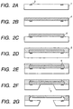
- Figs. 2A to 2G cross-sectional views along a line 2 - 2 in Fig. 1 show a method of producing the ink jet head of the present invention.
- FIG. 1 shows a schematic view showing the basic configuration of the present invention
- Figs. 2A to 2G cross-sectional views along a line 2 - 2 in Fig. 1
- FIG. 1 is a schematic view showing the basic configuration of the present invention
- Figs. 2A to 2G cross-sectional views along a line 2 - 2 in Fig. 1
- ink discharge energy generating elements 2 such as electrothermal converting elements or piezoelectric elements (cf. Fig. 2A).
- a soluble resin layer 4 on the substrate 1 bearing the ink discharge energy generating elements 2, there is formed a soluble resin layer 4, and an ink path pattern is formed in the resin layer 4, as shown in Fig. 2C.
- a pattern constituting a rib structure as shown in Figs. 4A to 4C and 5A to 5C is formed on the upper surface of the resin layer 4, corresponding to a portion where an ink supply aperture 3 (cf. Fig. 2E) is formed.
- a cover resin layer 5 As shown in Fig. 2D, and ink discharge openings 6 are formed in the cover resin layer 5 (Fig. 2E).
- ink discharge opening can be formed by a conventionally known method, such as etching with oxygen plasma, hole formation with an excimer laser, or exposure with ultraviolet or deep UV light.
- the ink supply aperture 3 is formed by chemical etching of the substrate.
- the substrate 1 can be composed of an Si (silicon) substrate, which can be anisotropically etched with a strong alkaline solution for example of KOH, NaOH or TMAH (Fig. 2G).
- the ink supply aperture may be formed prior to the formation of the patterns of the ink paths and the pattern constituting the rib structure (Figs. 2B and 2C) and the formation of the ink discharge openings (Figs. 2D and 2E).
- the rib structure of the present invention may be obtained, as explained in the foregoing, by forming a soluble resin layer on a flat surface, then patterning such resin layer and forming a cover resin layer thereon.
- the formation of the ink supply aperture after the formation of the ink path pattern, the rib-structure constituting pattern and the ink discharge openings may be achieved by a mechanical method such as drilling or by an optical energy such as of laser, but these methods are usually inadequate as they may cause damage to the already formed ink path pattern etc.
- the ink supply aperture is most preferably achieved by chemical etching, particularly anisotropic etching of Si substrate.
- the soluble resin layer 4 is dissolved out to form ink paths and bubble generating chambers as shown in Fig. 2G.
- the rib structure is formed above the ink supply aperture 3.
- the ink jet head of the present invention having the rib structure in a portion at the side of the ink paths, corresponding to the ink supply aperture, in the cover resin layer constituting the orifice plate, can improve the mechanical strength thereof and also can suppress the growth of the retentive bubbles.
- the rib preferably extends from the bubble generating chamber to the portion of the ink supply aperture.
- Figs. 12A to 12C illustrate an ink jet head of the representative configuration of the present invention
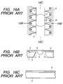
- Figs. 16A to 16C illustrate an ink jet head of the conventional configuration
- Figs. 17A to 17C illustrate an ink jet head in which partition walls for forming the ink path for the individual electrothermal converting element extend to the ink supply aperture in order to enhance the effect of the present invention.
- These ink jet heads are provided with ink droplet discharge means featuring the ink jet recording method described in the Japanese Patent Laid-Open Application Nos. 4-10940 and 4-10941, and are namely featured by a fact that the bubble at the ink discharge operation communicates with the external air.
- Figs. 12A to 12C are respectively a magnified plan view of the substrate bearing the electrothermal converting elements, and vertical cross-sectional views along lines 12B - 12B and 12C - 12C.
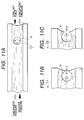
- a fine tube is filled with ink, and an end A of the tube is maintained at the atmospheric pressure while the other end B is maintained at atmospheric pressure -P (kPa). It is also assumed that the ink can freely enter and flow out from the tube.
- the pressure P means, in practice, the negative pressure by which the ink tank of the ink jet head sucks the ink. At the end A, the atmospheric pressure is balanced with the capillary force of the ink, whereby a meniscus is formed.
- the internal pressure of the bubble 9 can be represented by: atmospheric pressure -P + 2 ⁇ /r where ⁇ is the surface tension (dyn/cm) of the ink.
- ⁇ is the surface tension (dyn/cm) of the ink.
- the bubble 9 is brought closer to the end A and is made to communicate with the external air at a certain point.
- atmospheric pressure -P + 2 ⁇ /r > atmospheric pressure or P ⁇ 2 ⁇ /r the bubble 9 is discharged into the external air just as if a balloon shrinks since the internal pressure thereof is higher than the atmospheric pressure, whereby a meniscus is formed as indicated by a broken line.
- the present inventors have found a configuration having projections on the internal surface of the orifice plate, at a position directly above the ink supply aperture. It is observed that, in the presence of such projections, the retentive bubble, which sticks to and grows on the internal surface of the orifice plate, does not grow beyond the gap between such projections. Consequently, even if such retentive bubble comes into communication with the external air, there can be prevented the worst situation where the interior of the ink jet head is emptied if the gap between the projections is smaller than 2 ⁇ /P. However, the gap between the projections cannot be made smaller excessively.
- the gap of the projections should at least be 10 ⁇ m.
- a 2 ⁇ /P is generally within a range 40 ⁇ m ⁇ a ⁇ 200 ⁇ m. Consequently, a gap selected within a range from 10 to 40 ⁇ m functions preferably for the inks of various surface tensions and the ink tanks of various negative pressures, generally considered suitable for the ink jet head.
- the intrusion of the bubble into the ink path can be significantly reduced by a configuration in which the ink path includes, in a portion between the ink supply aperture of the substrate and the ink discharge energy generating element, a common area communicating with the adjacent ink discharge energy generating element. More specifically, in a configuration in which the portion from the vicinity of the ink supply aperture, where the retentive bubble tends to be generated, to the electrothermal converting element is separated as an individual ink path, such retentive bubble covers the end of the ink path at the side of the ink supply aperture and is thus trapped in the ink path.
- the ink path is provided, in the portion from the ink supply aperture of the substrate to the ink discharge energy generating element, with a common area communicating with the adjacent ink discharge energy generating element. Consequently the ink supply to individual ink discharge energy generating element in each ink path can be made at least through two paths on the substrate, so that, even if a part of the ink supply paths is covered by the retentive bubbles, the ink can be supplied through the remaining ink supply path and the possibility of intrusion of the retentive bubble into the ink path can therefore be significantly reduced.
- Figs. 12A to 12C are schematic views showing a representative ink jet head with the configuration of the present invention, in which the orifice plate is provided with plural projections in a position corresponding to the ink supply aperture and the ink path is provided, in the portion between the ink supply aperture of the substrate and the ink discharge energy generating element, with the common area communicating with the adjacent ink discharge energy generating element.
- the bubble may grow in two positions, namely the bubble sticking to and growing on the internal surface of the orifice plate and the bubble sticking to and growing on the end portion of the projection.
- the former retentive bubble which sticks to and grows on the internal surface of the orifice plate, can be suppressed by the projections as explained in the foregoing, whereby stable ink supply can be realized.
- the latter retentive bubble which sticks to and grows on the end portion of the projection, is observed to grow as shown in Figs. 4A to 4C.
- Such retentive bubble is also locally deformed slightly by the ink flow toward the ink discharge opening, for refilling the ink path after the ink droplet discharge, but the detrimental phenomenon as in the conventional configuration is not observed.
- the projections provided on the internal surface of the orifice plate are so constructed as to prevent the intrusion of the retentive bubble into the ink paths, and also because the ink path is provided, in the portion between the ink supply aperture of the substrate and the ink discharge energy generating element, with the common area communicating with the adjacent ink discharge energy generating element to enable ink supply from a wide area as indicated by arrows, whereby the ink supply does not easily become deficient.
- the ink in the ink path is not interrupted by the retentive bubble intruding in the ink path, whereby the deficiency of ink supply to the ink path and the emptying of the interior of the ink jet head by the communication of the bubble with the external air can mostly be prevented.
- an ink jet head of high reliability capable of stable ink droplet discharge.
- an ink jet head was prepared according to the procedure shown in Figs. 2A to 2G.
- the orifice plate was provided, in a portion above the ink supply aperture, with a rib structure as shown in Figs. 4A, 4B and 4C, wherein Figs. 4B and 4C are cross-sectional views respectively along lines 4B - 4B and 4C - 4C in Fig. 4A.
- the orifice plate alone of the ink jet head shown in Figs. 4A to 4C was prepared and was supported at both ends as shown in Fig. 7. Then the center of such orifice plate model was pushed with a push-pull gauge from the side of the orifice face (side without the ribs) as indicated by an arrow in Fig. 7, and the maximum stress at the breakage of the orifice plate was measured.
- the orifice plate model of the present example 1 showed a maximum stress of 7.5 ⁇ 10 10 Pa
- the orifice plate model of the conventional ink jet head shown in Figs. 3A to 3C, prepared and measured under the same conditions showed a maximum stress of 2.6 ⁇ 10 10 Pa.
- the rib structure as shown in Figs. 4A to 4C elevates the mechanical strength of the orifice plate of the ink jet head to about 3 times of that of the conventional configuration.
- the orifice plate showed slight swelling after a preservation test for 3 months in the ink at 60 °C, simulating the use of the ink jet head of the example 1 for a prolonged period.
- an ink jet head was prepared in the same manner as in the example 1.
- the orifice plate was provided, in a portion above the ink supply aperture, with a rib structure as shown in Figs. 5A, 5B, 5C and 5D, wherein Figs. 5B, 5C and 5D are cross-sectional views respectively along lines 5B - 5B, 5C - 5C and 5D - 5D in Fig. 5A.
- an ink jet head was prepared in the same manner as in the example 1.
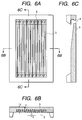
- the orifice plate was provided, in a portion above the ink supply aperture, with a rib structure as shown in Figs. 6A, 6B and 6C, wherein Figs. 6B and 6C are cross-sectional views respectively along lines 6B - 6B and 6C - 6C in Fig. 6A.
- the rib structure of the present example had a rounded shape in the 6B - 6B cross section and an inclined structure in the 6C - 6C cross section.
- an ink jet head was prepared in the same manner as in the example 1.
- the orifice plate was provided, in a portion above the ink supply aperture, with a rib structure as shown in Figs. 8A, 8B and 8C, wherein Figs. 8B and 8C are cross-sectional views respectively along lines 8B - 8B, and 8C - 8C in Fig. 8A.
- Fig. 9 is a schematic view of an ink jet head, representing a basic embodiment of the present invention and cut along a suitable plane for the ease of explanation.
- the electric wirings for driving the electrothermal converting elements are omitted.
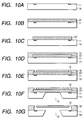
- Figs. 10A to 10G are cross-sectional views, along a line 10 - 10, of an ink jet substrate shown in Fig. 9, schematically showing the steps of preparation of the ink jet head of the present embodiment.
- a substrate 14 is provided with discharge energy generating elements 11 and an ink supply aperture 13, which consists of an oblong groove-shaped penetrating aperture.
- an array of electrothermal converting elements 11, serving as the ink discharge energy generating elements wherein such elements are arranged with a pitch of 300 dpi in each array and in mutually staggered manner in the both arrays.
- a cover resin layer 16 for constituting the ink path walls defining the ink paths, and, on the cover resin layer 16, there is provided an orifice plate 15 provided with discharge openings 12.
- the cover resin layer 16 and the orifice plate 15 are illustrated as separate members, but it is also possible to simultaneously form the cover resin layer 16 and the orifice plate 15 as an integral member, by applying the cover resin layer 16 for example by spin coating on the substrate 14.
- On the internal surface of the orifice plate in a position directly above the ink supply aperture 13, there are provided projections 17 for alleviating the detrimental effect of the bubbles, remaining in the ink jet head, on the ink discharge as explained in the foregoing.
- each ink path is provided, in a portion between the ink supply aperture of the substrate and the ink discharge energy generating element, with a common area communicating with the adjacent discharge energy generating element.
- the partition walls for defining the individual ink path corresponding to each electrothermal converting element are not extended to the ink supply aperture.
- the above-mentioned projection is preferably composed of a rib member along the direction of ink flow from the ink supply aperture 13 to the discharge opening 12, in order to minimize the flow resistance in the ink path, but it may also be composed, for example, of plural pillars as long as the aforementioned condition for the gap is satisfied.
- Such projection is desirably separated from the substrate in consideration of the ease of ink supply, and such separation of the projection is desirably such that the minimum distance from the end of the projection to the substrate is within a range of 10 - 40 ⁇ m as in the case of aforementioned gap.
- the projection 17 is composed of the above-mentioned rib member along the direction of the ink flow
- such rib may be contacted with the substrate to increase the strength of the orifice plate.
- the end portion of the rib may be tapered to reduce the flow resistance in the ink path.
- the projections 17 and the ink path walls 16 have a same height, but they may have different heights, as long as the minimum distance from the end of the projection to the substrate is within the above-mentioned range of 10 - 40 ⁇ m.
- partition walls are desirably so-constructed that the minimum distance from the end portion thereof to the substrate is within a range of 10 - 40 ⁇ m, as in the case of the projections.
- a substrate 14 bearing plural electrothermal converting elements 11 and wirings (not shown) required for driving such converting elements on a Si chip (Fig. 10A), and a soluble resin layer 22 is formed on the substrate 14 (Fig. 10B).
- the resin layer 22 is patterned, for example with a photolitographic process, to leave a pattern of the ink paths and to remove portions corresponding to the nozzle walls and the projections to be provided above the ink supply aperture according to the present invention (Fig. 10C).
- a cover resin layer 16 is formed on the soluble resin layer 22 bearing the ink path pattern (Fig. 10D), and portions of such cover resin layer 16 corresponding to the discharge openings 12 are removed (Fig. 10E).
- the ink supply aperture 13 is formed for example by chemically etching the substrate 14 from the rear side (Fig. 10F). More specifically, the supply aperture 13 is formed by anisotropic etching with a strong alkaline solution (KOH, NaOH or TMAH). Finally the soluble resin layer 22 is dissolved out (Fig. 10G) to obtain an ink jet head provided with the discharge openings 12, the ink supply aperture 13, the ink paths communicating therewith and the projections 17 formed on the orifice plate in a position directly above the ink supply aperture.
- the ink jet head of the present invention is completed by electrically connecting the chip with a wiring board for driving the electrothermal converting elements.
- the above-explained producing method for the ink jet head is particularly suitable for the ink jet head utilizing the ink jet recording method described in the Japanese Patent Laid-Open Application Nos. 4-10940 and 4-10941.
- These patent applications disclose an ink droplet discharging method featured by causing a bubble, generated on the electrothermal converting element by a recording signal, to communicate with the external air, and provide an ink jet head enabling to discharge a small ink droplet (50 pl. or less).
- the volume of the discharged ink droplet is principally determined by the volume of the ink present between the electrothermal converting element and the ink discharge opening.
- the configuration of the present invention is most effective in the above-explained ink jet head in which the (minimum) distance between the electrothermal converting element and the discharge opening does not exceed 30 ⁇ m in order to bring the bubble into communication with the external air, but is also effectively applicable to any ink jet head of the type for discharging the ink droplet perpendicularly to the surface of the substrate bearing the electrothermal converting elements.
- the ink jet head of the present invention can effectively relax the detrimental effect of the retentive bubble further, by driving the electrothermal converting elements in such a divided driving mode that the adjacent electrothermal converting elements are not activated at the same time.
- the ink jet heads were prepared according to the process shown in Figs. 10A to 10G, with a nozzle pitch 300 dpi in each array, the orifice plate of a thickness of 8 ⁇ m, and the projections featuring the present invention and the nozzle walls of a height of 12 ⁇ m.
- Dye black ink surface tension 47.8 dyn/cm, viscosity 1.8 cp, pH 9.8 made by Canon Inc. was used for evaluating the ink jet head.
- Figs. 12A to 12C are respectively a magnified elevation view of the substrate bearing the electrothermal converting elements, and cross-sectional views respectively along lines 12B - 12B and 12C - 12C.
- the projections in this example have a projected dimension of 20 ⁇ 150 ⁇ m onto the orifice plate, and are arranged with a pitch of 600 dpi (42.3 ⁇ m). Thus the gap between the adjacent projections is 22.3 ⁇ m at minimum.
- the ink jet head of the present example was driven with a discharge frequency of 10 kHz to continuously record a solid black image, and the time of continuation of such recording was compared with a conventional ink jet head.
- the ink jet head of this example could record the solid black image for a period about 4 times of that of the conventional head.
- Figs. 13A to 13C are respectively a magnified elevation view of the substrate bearing the electrothermal converting elements, and cross-sectional views respectively along lines 13B - 13B and 13C - 13C.
- the projections in this example have a projected dimension of 40 ⁇ 40 ⁇ m onto the orifice plate, and are arranged with a pitch of 80 ⁇ m (gap of 40 ⁇ m).
- the ink jet head of the present example was driven with a discharge frequency of 10 kHz to continuously record a solid black image, and the time of continuation of such recording was compared with a conventional ink jet head.
- the ink jet head of this example could record the solid black image for a period about 4 times of that of the conventional head.
- the present invention is effective also in the above-explained configuration.
- the reliability of the orifice plate is apparently low in terms of the strength.
- the orifice plate is composed of a resinous material, it may be swelled and deformed by the ink, eventually causing detrimental influence on the ink droplet discharging characteristics of the ink jet head.
- the following examples 7 and 8 propose to utilize the projections of the present invention also for securing the strength. More specifically, the projections are made to contact both the substrate and the orifice plate to attain a strength higher than the case in the absence of the projections on the orifice plate, thereby further improving the reliability.
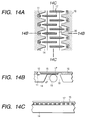
- Figs. 14A to 14C The ink jet head of this example is illustrated in Figs. 14A to 14C, Fig. 14A is a magnified elevation view of the substrate bearing the electrothermal converting elements, and Figs. 14B and 14C are cross-sectional views respectively along lines 14B - 14B and 14C - 14C.
- the projections in this example are featured by a fact that they contact both the substrate and the orifice plate to improve the strength of the orifice plate and that the width of the projections in a direction parallel to the orifice plate continuously decreases toward the electrothermal converting element in order to secure the ink supply to the nozzle and to reduce the flow resistance.
- the width of the projections of the present example is 20 ⁇ m at the widest part and 12 ⁇ m in the narrowest part in the projection onto the orifice plate, and the projections are arranged with a pitch of 600 dpi (42.3 ⁇ m). Consequently the gap between the projections is 22.3 ⁇ m at minimum.
- the ink jet head of the present example was driven with a discharge frequency of 10 kHz to continuously record a solid black image, and the time of continuation of such recording was compared with a conventional ink jet head.
- the ink jet head of this example could record the solid black image for a period about 4 times of that of the conventional head.
- the present invention is effective also in the above-explained configuration.
- Figs. 15A to 15C The ink jet head of this example is illustrated in Figs. 15A to 15C, Fig. 15A is a magnified elevation view of the substrate bearing the electrothermal converting elements, and Figs. 15B and 15C are cross-sectional views respectively along lines 15B - 15B and 15C - 15C.
- the projections in this example are featured by a fact that a same projection contacts both the substrate and the orifice plate across the ink supply aperture, thereby improving the strength of the orifice plate and that the width of the projections in a direction parallel to the orifice plate continuously decreases toward the electrothermal converting element in order to secure the ink supply to the nozzle and to reduce the flow resistance.
- the width of the projections of the present example is 20 ⁇ m at the widest part and 12 ⁇ m in the narrowest part in the projection onto the orifice plate, and the projections are arranged with a pitch of 600 dpi (42.3 ⁇ m). Consequently the gap between the projections is 22.3 ⁇ m at minimum.
- the ink jet head of the present example was driven with a discharge frequency of 10 kHz to continuously record a solid black image, and the time of continuation of such recording was compared with a conventional ink jet head.
- the ink jet head of this example could record the solid black image for a period about 3 times of that of the conventional head.
- the present invention is effective also in the above-explained configuration.
- an ink jet head comprising plural discharge energy generating elements for generating energy to be used for discharging ink droplets, ink discharge openings for discharging the ink droplets, a substrate bearing thereon an array of the plural discharge energy generating elements and an ink supply aperture consisting of a penetrating hole extending along the direction of array of the discharge energy generating elements, and an orifice plate provided with the ink discharge openings, in which the substrate and the orifice plate are mutually adjoined to define therebetween ink paths connecting the ink discharge openings and the ink supply aperture, wherein the orifice plate comprises plural projections in a position corresponding to the ink supply aperture.
Landscapes
- Physics & Mathematics (AREA)
- Geometry (AREA)
- Particle Formation And Scattering Control In Inkjet Printers (AREA)
- Ink Jet (AREA)
Applications Claiming Priority (6)
| Application Number | Priority Date | Filing Date | Title |
|---|---|---|---|
| JP30471996 | 1996-11-15 | ||
| JP30471996A JP3581504B2 (ja) | 1996-11-15 | 1996-11-15 | インクジェットプリントヘッド |
| JP304719/96 | 1996-11-15 | ||
| JP32073396 | 1996-11-16 | ||
| JP8320733A JPH10146979A (ja) | 1996-11-16 | 1996-11-16 | 液体噴射記録ヘッドおよびその製造方法 |
| JP320733/96 | 1996-11-16 |
Publications (3)
| Publication Number | Publication Date |
|---|---|
| EP0842776A2 true EP0842776A2 (fr) | 1998-05-20 |
| EP0842776A3 EP0842776A3 (fr) | 1999-10-06 |
| EP0842776B1 EP0842776B1 (fr) | 2004-02-11 |
Family
ID=26564022
Family Applications (1)
| Application Number | Title | Priority Date | Filing Date |
|---|---|---|---|
| EP97120009A Expired - Lifetime EP0842776B1 (fr) | 1996-11-15 | 1997-11-14 | Tête à jet d'encre |
Country Status (8)
| Country | Link |
|---|---|
| US (1) | US6137510A (fr) |
| EP (1) | EP0842776B1 (fr) |
| KR (1) | KR100269927B1 (fr) |
| CN (1) | CN1079739C (fr) |
| AU (1) | AU4517797A (fr) |
| CA (1) | CA2221119C (fr) |
| DE (1) | DE69727533T2 (fr) |
| ES (1) | ES2212032T3 (fr) |
Cited By (11)
| Publication number | Priority date | Publication date | Assignee | Title |
|---|---|---|---|---|
| EP0950524A3 (fr) * | 1998-04-16 | 2000-12-06 | Canon Kabushiki Kaisha | Tête d'éjection de liquide perfectionnée, cartouche pour une telle tête, appareil d'éjection de liquide muni d'une telle cartouche et procédé de fabrication de têtes d'éjection de liquide |
| DE10036878A1 (de) * | 2000-03-15 | 2001-09-27 | Ind Tech Res Inst | Chipstruktur eines Tintenstrahldruckkopfes und Verfahren zur Einschätzung der Lebensdauer durch Auffinden von Fehlern |
| WO2001054863A3 (fr) * | 2000-01-26 | 2002-04-04 | Hewlett Packard Co | Formation de fente d'alimentation en encre dans des tetes d'impression a jet d'encre |
| EP1024008A3 (fr) * | 1999-01-29 | 2002-04-17 | Canon Kabushiki Kaisha | Tête à éjection de liquide, méthode pour prévenir une défaillance d'éjection accidentelle de la tête, et procédé de fabrication de cette tête |
| US6739519B2 (en) | 2002-07-31 | 2004-05-25 | Hewlett-Packard Development Company, Lp. | Plurality of barrier layers |
| US6746106B1 (en) | 2003-01-30 | 2004-06-08 | Hewlett-Packard Development Company, L.P. | Fluid ejection device |
| US6896360B2 (en) | 2002-10-31 | 2005-05-24 | Hewlett-Packard Development Company, L.P. | Barrier feature in fluid channel |
| EP1570992A1 (fr) * | 2004-03-01 | 2005-09-07 | Sony Corporation | Tête et appareil d'éjection de liquide |
| WO2006102400A2 (fr) | 2005-03-21 | 2006-09-28 | Fujifilm Dimatix, Inc. | Dispositif d'ejection de gouttes |
| WO2007137614A1 (fr) * | 2006-06-01 | 2007-12-06 | Telecom Italia S.P.A. | Tête d'imprimante à jet d'encre |
| US7325309B2 (en) | 2004-06-08 | 2008-02-05 | Hewlett-Packard Development Company, L.P. | Method of manufacturing a fluid ejection device with a dry-film photo-resist layer |
Families Citing this family (32)
| Publication number | Priority date | Publication date | Assignee | Title |
|---|---|---|---|---|
| US6471326B2 (en) * | 1997-09-04 | 2002-10-29 | Canon Kabushiki Kaisha | Ink-jet head and ink-jet printing apparatus |
| JP2001171119A (ja) * | 1999-12-22 | 2001-06-26 | Canon Inc | 液体吐出記録ヘッド |
| US6830309B2 (en) | 2000-09-06 | 2004-12-14 | Canon Kabushiki Kaisha | Method for manufacturing ink jet recording head, ink jet recording head and ink jet recording method |
| JP4027282B2 (ja) | 2002-07-10 | 2007-12-26 | キヤノン株式会社 | インクジェット記録ヘッド |
| JP4027281B2 (ja) * | 2002-07-10 | 2007-12-26 | キヤノン株式会社 | インクジェット記録ヘッド |
| US7322104B2 (en) * | 2004-06-25 | 2008-01-29 | Canon Kabushiki Kaisha | Method for producing an ink jet head |
| US7629111B2 (en) * | 2004-06-28 | 2009-12-08 | Canon Kabushiki Kaisha | Liquid discharge head manufacturing method, and liquid discharge head obtained using this method |
| CN1968815B (zh) * | 2004-06-28 | 2013-05-01 | 佳能株式会社 | 排液头制造方法,和使用该方法得到的排液头 |
| US7625072B2 (en) | 2004-07-22 | 2009-12-01 | Canon Kabushiki Kaisha | Ink jet recording head and recording apparatus |
| WO2006009235A1 (fr) * | 2004-07-22 | 2006-01-26 | Canon Kabushiki Kaisha | Tête d’enregistrement à jet d’encre et appareil d’enregistrement |
| US7370944B2 (en) * | 2004-08-30 | 2008-05-13 | Eastman Kodak Company | Liquid ejector having internal filters |
| JP4724490B2 (ja) * | 2005-08-09 | 2011-07-13 | キヤノン株式会社 | 液体吐出ヘッド |
| JP2007283501A (ja) * | 2006-04-12 | 2007-11-01 | Canon Inc | インクジェット記録ヘッド |
| JP2008018556A (ja) * | 2006-07-11 | 2008-01-31 | Canon Inc | インクジェット記録ヘッド |
| JP5171002B2 (ja) * | 2006-09-25 | 2013-03-27 | キヤノン株式会社 | インクジェット記録ヘッドの製造方法 |
| JP5100243B2 (ja) * | 2007-08-07 | 2012-12-19 | キヤノン株式会社 | 液体吐出ヘッド |
| US7946700B2 (en) * | 2007-10-31 | 2011-05-24 | Hewlett-Packard Development Company, L.P. | Printer with print head platen |
| JP2009119650A (ja) * | 2007-11-13 | 2009-06-04 | Canon Inc | インクジェットヘッドの製造方法 |
| US20090136875A1 (en) * | 2007-11-15 | 2009-05-28 | Canon Kabushiki Kaisha | Manufacturing method of liquid ejection head |
| JP5031534B2 (ja) * | 2007-11-30 | 2012-09-19 | キヤノン株式会社 | インクジェット記録ヘッド |
| JP5084478B2 (ja) | 2007-12-07 | 2012-11-28 | キヤノン株式会社 | インクジェット記録ヘッドおよびインクジェット記録装置 |
| JP2009220286A (ja) * | 2008-03-13 | 2009-10-01 | Canon Inc | 液体吐出記録ヘッド及その製造方法 |
| MX2011005567A (es) * | 2008-11-25 | 2012-01-25 | Procter & Gamble | Composiciones para el cuidado bucal con estetica mejorada y silicio fundido. |
| JP4942218B2 (ja) * | 2008-12-16 | 2012-05-30 | キヤノン株式会社 | 液体吐出ヘッドの製造方法 |
| JP4656670B2 (ja) * | 2008-12-19 | 2011-03-23 | キヤノン株式会社 | 液体吐出ヘッド及び液体吐出ヘッドの製造方法 |
| JP5388615B2 (ja) * | 2009-02-06 | 2014-01-15 | キヤノン株式会社 | インクジェット記録ヘッド |
| JP5279686B2 (ja) * | 2009-11-11 | 2013-09-04 | キヤノン株式会社 | 液体吐出ヘッドの製造方法 |
| US8434229B2 (en) * | 2010-11-24 | 2013-05-07 | Canon Kabushiki Kaisha | Liquid ejection head manufacturing method |
| JP5302378B2 (ja) | 2011-01-14 | 2013-10-02 | パナソニック株式会社 | インクジェットヘッド |
| WO2016068945A1 (fr) | 2014-10-30 | 2016-05-06 | Hewlett-Packard Development Company, L.P. | Tête d'impression à jet d'encre |
| KR101641593B1 (ko) | 2014-12-22 | 2016-07-21 | 주식회사 포스코 | 슬리브 공급장치 |
| WO2025137010A1 (fr) * | 2023-12-18 | 2025-06-26 | Hewlett-Packard Development Company, L.P. | Dispositif de distribution de fluide comprenant un régulateur pour diriger un gaz transversal vers une buse |
Family Cites Families (21)
| Publication number | Priority date | Publication date | Assignee | Title |
|---|---|---|---|---|
| US4229265A (en) * | 1979-08-09 | 1980-10-21 | The Mead Corporation | Method for fabricating and the solid metal orifice plate for a jet drop recorder produced thereby |
| JPH0773915B2 (ja) * | 1985-12-06 | 1995-08-09 | ヒューレット・パッカード・カンパニー | 熱インクジエツト・プリントヘツド |
| GB8607313D0 (en) * | 1986-03-25 | 1986-04-30 | Ici Plc | Pharmaceutical compositions |
| DE3917434A1 (de) * | 1989-05-29 | 1989-11-09 | Siemens Ag | Mehrschichtig aufgebauter tintendruckkopf mit durch selektives aetzen erzeugten tintenkanaelen |
| DE69029780T2 (de) * | 1989-08-31 | 1997-07-10 | Canon Kk | Absaug-Regeneriervorrichtung für ein Tintenstrahlaufzeichnungsgerät |
| JP2752486B2 (ja) * | 1989-12-29 | 1998-05-18 | キヤノン株式会社 | インクジェット記録ヘッドおよびその検査方法ならびにインクジェット記録装置 |
| ATE132807T1 (de) * | 1990-01-17 | 1996-01-15 | Canon Kk | Flüssigkeitsstrahl-aufzeichnungskopf |
| ES2073670T3 (es) * | 1990-02-02 | 1995-08-16 | Canon Kk | Aparato para la impresion por chorros de tinta y cabezal para la impresion por chorros de tinta. |
| US5227812A (en) * | 1990-02-26 | 1993-07-13 | Canon Kabushiki Kaisha | Liquid jet recording head with bump connector wiring |
| JPH0410942A (ja) * | 1990-04-27 | 1992-01-16 | Canon Inc | 液体噴射方法および該方法を用いた記録装置 |
| JP2783647B2 (ja) * | 1990-04-27 | 1998-08-06 | キヤノン株式会社 | 液体噴射方法および該方法を用いた記録装置 |
| JPH0410941A (ja) * | 1990-04-27 | 1992-01-16 | Canon Inc | 液滴噴射方法及び該方法を用いた記録装置 |
| DE69327762T2 (de) * | 1992-10-20 | 2000-07-06 | Canon K.K., Tokio/Tokyo | Farbstrahldruckkopf, dessen Herstellungsverfahren und zugehöriges Farbstrahlgerät |
| JP3143307B2 (ja) * | 1993-02-03 | 2001-03-07 | キヤノン株式会社 | インクジェット記録ヘッドの製造方法 |
| JP2835681B2 (ja) * | 1993-05-14 | 1998-12-14 | 株式会社テイエルブイ | 熱応動式スチ―ムトラップ |
| US5463413A (en) * | 1993-06-03 | 1995-10-31 | Hewlett-Packard Company | Internal support for top-shooter thermal ink-jet printhead |
| US5322594A (en) * | 1993-07-20 | 1994-06-21 | Xerox Corporation | Manufacture of a one piece full width ink jet printing bar |
| US5696543A (en) * | 1993-12-10 | 1997-12-09 | Canon Kabushiki Kaisha | Recording head which detects temperature of an element chip and corrects for variations in that detected temperature, and cartridge and apparatus having such a head |
| US5574488A (en) * | 1993-12-22 | 1996-11-12 | Canon Kabushiki Kaisha | Liquid jet head, liquid jet head cartridge, and liquid jet apparatus |
| US5774149A (en) * | 1994-08-24 | 1998-06-30 | Canon Kabushiki Kaisha | Ink jet recording head and apparatus |
| JP3706671B2 (ja) * | 1995-04-14 | 2005-10-12 | キヤノン株式会社 | 液体吐出ヘッド、液体吐出ヘッドを用いたヘッドカートリッジ、液体吐出装置、および液体吐出方法 |
-
1997
- 1997-11-13 US US08/969,837 patent/US6137510A/en not_active Expired - Lifetime
- 1997-11-14 DE DE69727533T patent/DE69727533T2/de not_active Expired - Lifetime
- 1997-11-14 ES ES97120009T patent/ES2212032T3/es not_active Expired - Lifetime
- 1997-11-14 AU AU45177/97A patent/AU4517797A/en not_active Abandoned
- 1997-11-14 EP EP97120009A patent/EP0842776B1/fr not_active Expired - Lifetime
- 1997-11-14 CN CN97122680A patent/CN1079739C/zh not_active Expired - Fee Related
- 1997-11-14 CA CA002221119A patent/CA2221119C/fr not_active Expired - Fee Related
- 1997-11-15 KR KR1019970060266A patent/KR100269927B1/ko not_active Expired - Fee Related
Cited By (19)
| Publication number | Priority date | Publication date | Assignee | Title |
|---|---|---|---|---|
| EP0950524A3 (fr) * | 1998-04-16 | 2000-12-06 | Canon Kabushiki Kaisha | Tête d'éjection de liquide perfectionnée, cartouche pour une telle tête, appareil d'éjection de liquide muni d'une telle cartouche et procédé de fabrication de têtes d'éjection de liquide |
| US6474780B1 (en) | 1998-04-16 | 2002-11-05 | Canon Kabushiki Kaisha | Liquid discharge head, cartridge having such head, liquid discharge apparatus provided with such cartridge, and method for manufacturing liquid discharge heads |
| EP1024008A3 (fr) * | 1999-01-29 | 2002-04-17 | Canon Kabushiki Kaisha | Tête à éjection de liquide, méthode pour prévenir une défaillance d'éjection accidentelle de la tête, et procédé de fabrication de cette tête |
| US6520626B1 (en) | 1999-01-29 | 2003-02-18 | Canon Kabushiki Kaisha | Liquid ejection head, method for preventing accidental non-eject using the ejection head and manufacturing method of the ejection head |
| WO2001054863A3 (fr) * | 2000-01-26 | 2002-04-04 | Hewlett Packard Co | Formation de fente d'alimentation en encre dans des tetes d'impression a jet d'encre |
| DE10036878A1 (de) * | 2000-03-15 | 2001-09-27 | Ind Tech Res Inst | Chipstruktur eines Tintenstrahldruckkopfes und Verfahren zur Einschätzung der Lebensdauer durch Auffinden von Fehlern |
| DE10036878C2 (de) * | 2000-03-15 | 2003-08-28 | Ind Tech Res Inst | Druckchip für einen nach dem Bubble-Jet-Verfahren arbeitenden Tintenstrahldruckkopf mit Einrichtung zum Abschätzen der Lebensdauer und ein Verfahren zum Einschätzen derselben |
| US7226149B2 (en) | 2002-07-31 | 2007-06-05 | Hewlett-Packard Development Company, L.P. | Plurality of barrier layers |
| US6739519B2 (en) | 2002-07-31 | 2004-05-25 | Hewlett-Packard Development Company, Lp. | Plurality of barrier layers |
| US6896360B2 (en) | 2002-10-31 | 2005-05-24 | Hewlett-Packard Development Company, L.P. | Barrier feature in fluid channel |
| US6746106B1 (en) | 2003-01-30 | 2004-06-08 | Hewlett-Packard Development Company, L.P. | Fluid ejection device |
| EP1570992A1 (fr) * | 2004-03-01 | 2005-09-07 | Sony Corporation | Tête et appareil d'éjection de liquide |
| US7470004B2 (en) | 2004-03-01 | 2008-12-30 | Sony Corporation | Liquid ejection head and liquid ejection device |
| US7325309B2 (en) | 2004-06-08 | 2008-02-05 | Hewlett-Packard Development Company, L.P. | Method of manufacturing a fluid ejection device with a dry-film photo-resist layer |
| US7979987B2 (en) | 2004-06-08 | 2011-07-19 | Hewlett-Packard Development Company, L.P. | Method of manufacturing fluid ejection device with dry-film photo-resist layer |
| WO2006102400A2 (fr) | 2005-03-21 | 2006-09-28 | Fujifilm Dimatix, Inc. | Dispositif d'ejection de gouttes |
| EP1861254A4 (fr) * | 2005-03-21 | 2010-07-28 | Fujifilm Dimatix Inc | Dispositif d'ejection de gouttes |
| WO2007137614A1 (fr) * | 2006-06-01 | 2007-12-06 | Telecom Italia S.P.A. | Tête d'imprimante à jet d'encre |
| US8292408B2 (en) | 2006-06-01 | 2012-10-23 | Telecom Italia S.P.A. | Inkjet printhead |
Also Published As
| Publication number | Publication date |
|---|---|
| US6137510A (en) | 2000-10-24 |
| KR100269927B1 (ko) | 2000-10-16 |
| CN1079739C (zh) | 2002-02-27 |
| CA2221119C (fr) | 2002-04-02 |
| AU4517797A (en) | 1998-05-21 |
| EP0842776A3 (fr) | 1999-10-06 |
| CA2221119A1 (fr) | 1998-05-15 |
| ES2212032T3 (es) | 2004-07-16 |
| DE69727533T2 (de) | 2005-01-05 |
| EP0842776B1 (fr) | 2004-02-11 |
| DE69727533D1 (de) | 2004-03-18 |
| KR19980042467A (ko) | 1998-08-17 |
| CN1182677A (zh) | 1998-05-27 |
Similar Documents
| Publication | Publication Date | Title |
|---|---|---|
| EP0842776B1 (fr) | Tête à jet d'encre | |
| EP0924077B1 (fr) | Filtre faisant partie d'un élément chauffant pour éliminer les impuretés d'un liquide et sa méthode de fabrication | |
| KR100408269B1 (ko) | 잉크제트 프린트헤드 | |
| KR100554807B1 (ko) | 유체액적을분사하기위한프린트헤드및유체액적형성방법 | |
| JP3957851B2 (ja) | 液体吐出方法 | |
| KR20010040355A (ko) | 마이크로인젝터내의 가상 밸브로서 버블을 이용하여유체를 분출하는 장치 및 방법 | |
| EP0924078B1 (fr) | Filtre pour éliminer les impuretés d'un fluide et sa méthode de fabrication | |
| US7018015B2 (en) | Substrate and method of forming substrate for fluid ejection device | |
| KR20040060816A (ko) | 잉크 젯 기록 헤드, 잉크 젯 기록 헤드의 제조 방법 및잉크 젯 기록 헤드 제조용 기판 | |
| US6951383B2 (en) | Fluid ejection device having a substrate to filter fluid and method of manufacture | |
| US6502918B1 (en) | Feature in firing chamber of fluid ejection device | |
| KR20020026076A (ko) | 잉크젯 프린터 헤드 | |
| US5461406A (en) | Method and apparatus for elimination of misdirected satellite drops in thermal ink jet printhead | |
| KR100320689B1 (ko) | 액체 토출 방법 및 액체 토출 헤드 | |
| JP3581504B2 (ja) | インクジェットプリントヘッド | |
| AU780024B2 (en) | Ink jet head | |
| JP2000158657A (ja) | インクジェットプリントヘッド及び該ヘッドを搭載するインクジェットプリンティングデバイス | |
| JP3559698B2 (ja) | インクジェットプリントヘッド、インクジェットプリンテイングデバイスおよびそれらの製造方法 | |
| JP3684046B2 (ja) | インクジェット記録ヘッド、及びインクジェット記録装置 | |
| JP2023108679A (ja) | 記録素子基板及びその製造方法 | |
| JP2024040783A (ja) | 液体吐出ヘッド及びその製造方法 | |
| JP4704179B2 (ja) | インクジェットヘッドおよびインクジェットヘッドの製造方法 |
Legal Events
| Date | Code | Title | Description |
|---|---|---|---|
| PUAI | Public reference made under article 153(3) epc to a published international application that has entered the european phase |
Free format text: ORIGINAL CODE: 0009012 |
|
| AK | Designated contracting states |
Kind code of ref document: A2 Designated state(s): DE ES FR GB IT NL |
|
| AX | Request for extension of the european patent |
Free format text: AL;LT;LV;MK;RO;SI |
|
| PUAL | Search report despatched |
Free format text: ORIGINAL CODE: 0009013 |
|
| AK | Designated contracting states |
Kind code of ref document: A3 Designated state(s): AT BE CH DE DK ES FI FR GB GR IE IT LI LU MC NL PT SE |
|
| AX | Request for extension of the european patent |
Free format text: AL;LT;LV;MK;RO;SI |
|
| RIC1 | Information provided on ipc code assigned before grant |
Free format text: 6B 41J 2/14 A, 6B 41J 2/05 B |
|
| 17P | Request for examination filed |
Effective date: 20000221 |
|
| AKX | Designation fees paid |
Free format text: DE ES FR GB IT NL |
|
| GRAH | Despatch of communication of intention to grant a patent |
Free format text: ORIGINAL CODE: EPIDOS IGRA |
|
| GRAS | Grant fee paid |
Free format text: ORIGINAL CODE: EPIDOSNIGR3 |
|
| GRAA | (expected) grant |
Free format text: ORIGINAL CODE: 0009210 |
|
| AK | Designated contracting states |
Kind code of ref document: B1 Designated state(s): DE ES FR GB IT NL |
|
| REG | Reference to a national code |
Ref country code: GB Ref legal event code: FG4D |
|
| REF | Corresponds to: |
Ref document number: 69727533 Country of ref document: DE Date of ref document: 20040318 Kind code of ref document: P |
|
| REG | Reference to a national code |
Ref country code: ES Ref legal event code: FG2A Ref document number: 2212032 Country of ref document: ES Kind code of ref document: T3 |
|
| ET | Fr: translation filed | ||
| PLBE | No opposition filed within time limit |
Free format text: ORIGINAL CODE: 0009261 |
|
| STAA | Information on the status of an ep patent application or granted ep patent |
Free format text: STATUS: NO OPPOSITION FILED WITHIN TIME LIMIT |
|
| 26N | No opposition filed |
Effective date: 20041112 |
|
| PGFP | Annual fee paid to national office [announced via postgrant information from national office to epo] |
Ref country code: NL Payment date: 20081118 Year of fee payment: 12 |
|
| PGFP | Annual fee paid to national office [announced via postgrant information from national office to epo] |
Ref country code: ES Payment date: 20081007 Year of fee payment: 12 |
|
| PGFP | Annual fee paid to national office [announced via postgrant information from national office to epo] |
Ref country code: IT Payment date: 20081119 Year of fee payment: 12 |
|
| PGFP | Annual fee paid to national office [announced via postgrant information from national office to epo] |
Ref country code: FR Payment date: 20081124 Year of fee payment: 12 |
|
| REG | Reference to a national code |
Ref country code: NL Ref legal event code: V1 Effective date: 20100601 |
|
| REG | Reference to a national code |
Ref country code: FR Ref legal event code: ST Effective date: 20100730 |
|
| PG25 | Lapsed in a contracting state [announced via postgrant information from national office to epo] |
Ref country code: NL Free format text: LAPSE BECAUSE OF NON-PAYMENT OF DUE FEES Effective date: 20100601 Ref country code: FR Free format text: LAPSE BECAUSE OF NON-PAYMENT OF DUE FEES Effective date: 20091130 |
|
| REG | Reference to a national code |
Ref country code: ES Ref legal event code: FD2A Effective date: 20110307 |
|
| PG25 | Lapsed in a contracting state [announced via postgrant information from national office to epo] |
Ref country code: IT Free format text: LAPSE BECAUSE OF NON-PAYMENT OF DUE FEES Effective date: 20091114 |
|
| PG25 | Lapsed in a contracting state [announced via postgrant information from national office to epo] |
Ref country code: ES Free format text: LAPSE BECAUSE OF NON-PAYMENT OF DUE FEES Effective date: 20110304 |
|
| PG25 | Lapsed in a contracting state [announced via postgrant information from national office to epo] |
Ref country code: ES Free format text: LAPSE BECAUSE OF NON-PAYMENT OF DUE FEES Effective date: 20091115 |
|
| PGFP | Annual fee paid to national office [announced via postgrant information from national office to epo] |
Ref country code: DE Payment date: 20141130 Year of fee payment: 18 Ref country code: GB Payment date: 20141124 Year of fee payment: 18 |
|
| REG | Reference to a national code |
Ref country code: DE Ref legal event code: R119 Ref document number: 69727533 Country of ref document: DE |
|
| GBPC | Gb: european patent ceased through non-payment of renewal fee |
Effective date: 20151114 |
|
| PG25 | Lapsed in a contracting state [announced via postgrant information from national office to epo] |
Ref country code: GB Free format text: LAPSE BECAUSE OF NON-PAYMENT OF DUE FEES Effective date: 20151114 Ref country code: DE Free format text: LAPSE BECAUSE OF NON-PAYMENT OF DUE FEES Effective date: 20160601 |