EP0842812A2 - Siège auxiliaire à double pivot à tablette coulissante utilitaire. - Google Patents
Siège auxiliaire à double pivot à tablette coulissante utilitaire. Download PDFInfo
- Publication number
- EP0842812A2 EP0842812A2 EP97203452A EP97203452A EP0842812A2 EP 0842812 A2 EP0842812 A2 EP 0842812A2 EP 97203452 A EP97203452 A EP 97203452A EP 97203452 A EP97203452 A EP 97203452A EP 0842812 A2 EP0842812 A2 EP 0842812A2
- Authority
- EP
- European Patent Office
- Prior art keywords
- seat
- buddy
- slide rail
- rail assembly
- utility tray
- Prior art date
- Legal status (The legal status is an assumption and is not a legal conclusion. Google has not performed a legal analysis and makes no representation as to the accuracy of the status listed.)
- Granted
Links
- 230000009977 dual effect Effects 0.000 title claims abstract description 23
- 238000003860 storage Methods 0.000 claims abstract description 33
- 125000006850 spacer group Chemical group 0.000 claims description 5
- 235000013361 beverage Nutrition 0.000 claims description 4
- 239000011248 coating agent Substances 0.000 claims description 3
- 238000000576 coating method Methods 0.000 claims description 3
- 238000009434 installation Methods 0.000 claims description 2
- 238000009313 farming Methods 0.000 description 4
- 238000003306 harvesting Methods 0.000 description 4
- 238000000926 separation method Methods 0.000 description 4
- 238000013461 design Methods 0.000 description 3
- 238000012423 maintenance Methods 0.000 description 2
- 239000000463 material Substances 0.000 description 2
- 239000010813 municipal solid waste Substances 0.000 description 2
- 238000009825 accumulation Methods 0.000 description 1
- 238000004378 air conditioning Methods 0.000 description 1
- 230000036626 alertness Effects 0.000 description 1
- 239000000428 dust Substances 0.000 description 1
- 230000000694 effects Effects 0.000 description 1
- 239000011521 glass Substances 0.000 description 1
- 238000004519 manufacturing process Methods 0.000 description 1
- 238000012806 monitoring device Methods 0.000 description 1
- 238000012545 processing Methods 0.000 description 1
- 238000011160 research Methods 0.000 description 1
- 238000012552 review Methods 0.000 description 1
Images



Classifications
-
- B—PERFORMING OPERATIONS; TRANSPORTING
- B60—VEHICLES IN GENERAL
- B60R—VEHICLES, VEHICLE FITTINGS, OR VEHICLE PARTS, NOT OTHERWISE PROVIDED FOR
- B60R7/00—Stowing or holding appliances inside vehicle primarily intended for personal property smaller than suit-cases, e.g. travelling articles, or maps
- B60R7/04—Stowing or holding appliances inside vehicle primarily intended for personal property smaller than suit-cases, e.g. travelling articles, or maps in driver or passenger space, e.g. using racks
- B60R7/043—Stowing or holding appliances inside vehicle primarily intended for personal property smaller than suit-cases, e.g. travelling articles, or maps in driver or passenger space, e.g. using racks mounted on or under a seat
-
- A—HUMAN NECESSITIES
- A01—AGRICULTURE; FORESTRY; ANIMAL HUSBANDRY; HUNTING; TRAPPING; FISHING
- A01D—HARVESTING; MOWING
- A01D67/00—Undercarriages or frames specially adapted for harvesters or mowers; Mechanisms for adjusting the frame; Platforms
- A01D67/04—Seats
-
- B—PERFORMING OPERATIONS; TRANSPORTING
- B60—VEHICLES IN GENERAL
- B60N—SEATS SPECIALLY ADAPTED FOR VEHICLES; VEHICLE PASSENGER ACCOMMODATION NOT OTHERWISE PROVIDED FOR
- B60N2/00—Seats specially adapted for vehicles; Arrangement or mounting of seats in vehicles
- B60N2/24—Seats specially adapted for vehicles; Arrangement or mounting of seats in vehicles for particular purposes or particular vehicles
- B60N2/30—Non-dismountable or dismountable seats storable in a non-use position, e.g. foldable spare seats
- B60N2/3002—Non-dismountable or dismountable seats storable in a non-use position, e.g. foldable spare seats back-rest movements
- B60N2/3004—Non-dismountable or dismountable seats storable in a non-use position, e.g. foldable spare seats back-rest movements by rotation only
- B60N2/3009—Non-dismountable or dismountable seats storable in a non-use position, e.g. foldable spare seats back-rest movements by rotation only about transversal axis
- B60N2/3011—Non-dismountable or dismountable seats storable in a non-use position, e.g. foldable spare seats back-rest movements by rotation only about transversal axis the back-rest being hinged on the cushion, e.g. "portefeuille movement"
-
- B—PERFORMING OPERATIONS; TRANSPORTING
- B60—VEHICLES IN GENERAL
- B60N—SEATS SPECIALLY ADAPTED FOR VEHICLES; VEHICLE PASSENGER ACCOMMODATION NOT OTHERWISE PROVIDED FOR
- B60N2/00—Seats specially adapted for vehicles; Arrangement or mounting of seats in vehicles
- B60N2/24—Seats specially adapted for vehicles; Arrangement or mounting of seats in vehicles for particular purposes or particular vehicles
- B60N2/30—Non-dismountable or dismountable seats storable in a non-use position, e.g. foldable spare seats
- B60N2/3038—Cushion movements
- B60N2/304—Cushion movements by rotation only
- B60N2/3045—Cushion movements by rotation only about transversal axis
- B60N2/305—Cushion movements by rotation only about transversal axis the cushion being hinged on the vehicle frame
-
- B—PERFORMING OPERATIONS; TRANSPORTING
- B60—VEHICLES IN GENERAL
- B60N—SEATS SPECIALLY ADAPTED FOR VEHICLES; VEHICLE PASSENGER ACCOMMODATION NOT OTHERWISE PROVIDED FOR
- B60N2/00—Seats specially adapted for vehicles; Arrangement or mounting of seats in vehicles
- B60N2/24—Seats specially adapted for vehicles; Arrangement or mounting of seats in vehicles for particular purposes or particular vehicles
- B60N2/38—Seats specially adapted for vehicles; Arrangement or mounting of seats in vehicles for particular purposes or particular vehicles specially constructed for use on tractors or like off-road vehicles
-
- B—PERFORMING OPERATIONS; TRANSPORTING
- B60—VEHICLES IN GENERAL
- B60N—SEATS SPECIALLY ADAPTED FOR VEHICLES; VEHICLE PASSENGER ACCOMMODATION NOT OTHERWISE PROVIDED FOR
- B60N2/00—Seats specially adapted for vehicles; Arrangement or mounting of seats in vehicles
- B60N2/75—Arm-rests
- B60N2/753—Arm-rests movable to an inoperative position
-
- B—PERFORMING OPERATIONS; TRANSPORTING
- B60—VEHICLES IN GENERAL
- B60N—SEATS SPECIALLY ADAPTED FOR VEHICLES; VEHICLE PASSENGER ACCOMMODATION NOT OTHERWISE PROVIDED FOR
- B60N2/00—Seats specially adapted for vehicles; Arrangement or mounting of seats in vehicles
- B60N2/75—Arm-rests
- B60N2/763—Arm-rests adjustable
- B60N2/767—Angle adjustment
-
- B—PERFORMING OPERATIONS; TRANSPORTING
- B60—VEHICLES IN GENERAL
- B60N—SEATS SPECIALLY ADAPTED FOR VEHICLES; VEHICLE PASSENGER ACCOMMODATION NOT OTHERWISE PROVIDED FOR
- B60N2/00—Seats specially adapted for vehicles; Arrangement or mounting of seats in vehicles
- B60N2/75—Arm-rests
- B60N2/763—Arm-rests adjustable
- B60N2/773—Longitudinal adjustment
-
- B—PERFORMING OPERATIONS; TRANSPORTING
- B60—VEHICLES IN GENERAL
- B60N—SEATS SPECIALLY ADAPTED FOR VEHICLES; VEHICLE PASSENGER ACCOMMODATION NOT OTHERWISE PROVIDED FOR
- B60N2/00—Seats specially adapted for vehicles; Arrangement or mounting of seats in vehicles
- B60N2/75—Arm-rests
- B60N2/79—Adaptations for additional use of the arm-rests
- B60N2/797—Adaptations for additional use of the arm-rests for use as electrical control means, e.g. switches
Definitions
- This invention relates to the improvement of the buddy seat in the cab of an agricultural combine harvester. More specifically it relates to a dual pivoting buddy seat with a sliding utility tray.
- a combine harvester generally includes a header which cuts the crop.
- the header then moves the cut crop into a feeder house.
- the feeder house lifts the cut crop into the threshing and separation areas of the combine.
- the grain is separated from the stalk by a rotor.
- the grain is then moved and stored in a grain tank.
- the chaff and trash are deposited from the rear of the combine.
- An operator usually runs these various operations from a glass-enclosed cab.
- a cab is located behind the header and in front of the threshing and separation areas of the combine. An operator can observe most of the combine activities from the cab.
- One aspect of maintaining the operator's alertness is to provide a second seat or buddy seat in the cab.
- the design of the buddy seat should be such as to minimize the space required.
- a flat utility area which could be provided, might also help keep the driver alert by allowing the placement and storage of various items. For instance, a beverage holder or lunch box holder are examples of items which an operator might wish to save.
- the effort to design and manufacture a buddy seat and storage area which is proximal to an operator of a farm vehicle is considerable.
- the research effort has followed several paths.
- Most devices have been designed to move the operator's chair or buddy seat to allow for maximum comfort during farming operations.
- the seat back of the buddy seat is fixed to the cab's rear wall.
- the seat base is pivotally affixed to the rear wall of the cab and is lifted up or pushed down when not in use.
- the buddy seat is located behind and towards the left side of the operator. While this does not impact the operator's view, it is difficult for the operator to utilize the buddy seat as storage or utility area.
- the operator would have to reach back to get any items.
- the operator utilizing a lap-top computer or monitoring device would not be able to easily view the device.
- US-A-3,583,518 discloses an operator's station for a self-propelled agricultural machine.
- the operator's chair is capable of sliding rearward to allow for the operator to stand while driving the combine.
- US-A-4,364,602 discloses a seat support structure for the driving of an earth moving machine. The entire seat structure slides rearward and then up the rear of the driving station. This chair is complex to move and does not allow the operator to easily move the chair during vehicle operations.
- US-A-4,915,438 discloses a vehicular seating apparatus.
- An assistant driver's seat is moved to the side and allows the driver to go to the rear of the vehicle during operations.
- the assistant's seat moves towards the driver's seat to create the space.
- No storage space is developed as a result of the movement.
- the movement mechanism consists of several complex tracks on which the entire chair slides. This mechanism is complex and subject to becoming jammed if an object is dropped on track.
- US-A-5,029,929 discloses a bed arrangement in the coupe area of a vehicle.
- the seat back of the operator's chair comprises a pivoted upper and lower portions.
- the upper portion of the seat back is positioned so as to be part of a bed.
- the remaining portion of the bed is pivotally affixed to the rear wall of the cab.
- the main drawback to this design is the inability of the operator to utilize the bed or any storage space during the operation of the vehicle.
- a buddy seat which is positioned in a cab of a combine harvester, such that the operator has an unobstructed view of farming operations, but can easily be used as a storage or utility area.
- the utility area on the one hand should be located proximal to the operator's chair and on the other hand should use a minimum amount of space in a combine cab.
- a dual pivoting buddy seat for installation in a vehicle adjacent an operator's chair mounted on a floor, said buddy seat comprising:
- the utility tray has a utility area and beverage holder which may be pivoted and/or moved to an extended positioned proximal to an operator seated in the operator's chair for easy access to the utility tray.
- the slide rail assembly may be placed on a moulded rail guide on the utility tray and a sliding strip on the seat back.
- the friction between the utility tray, seat back and slide rail assembly may be controlled by adjustment screws with spacers. By loosening or tightening the adjustment screws, the friction between the slide rail assembly and utility tray or seat back is controlled.
- the dual pivoting buddy seat with sliding utility tray may pivot so as to provide easy access to the storage area.
- the slide rail assembly may have an electroplated coating, preferably black, so as to minimize friction.
- the seat back may comprise a sliding strip in contact with the slide rail assembly so as to minimize friction.
- a stop pin oriented towards the centre of the seat back and contacting a moulded stop on the rail guide, may be used to limit the length of slide of the slide rail assembly, thereby preventing the utility tray and seat back from becoming separated from the slide rail assembly.
- the utility tray may slide along said slide rail assembly creating a rectangular opening large enough to accommodate a conventional lunch box.
- the utility area is large enough to accommodate a lap-top computer or monitor.
- the buddy seat may have colour and styling matched contoured seat cushions on the seat base and seat back.
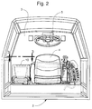
- An embodiment of the invention is shown within the cab 2 of a combine 1.
- a typical combine harvester has a header for cutting a crop. As the combine 1 and header are moved forward, the grain and stalk are cut by the header. The header moves the cut crop material into an auger trough. A transverse auger pushes the grain and stalk in the auger trough to the centre of the header. Located at the centre of the header is the feeder house or elevator. The feeder house moves the grain and stalks rearward into the threshing and separation systems of the combine 1. After processing and separation, the processed grain is stored in a grain tank located near the top of the combine 1. The trash or chaff is ejected from the rear of the combine.
- the operator runs the combine 1 from the cab 2 located behind the header and at the front of the combine 1. From the cab 2 the operator can observe most of the various combine functions.
- the cab usually has a large glass window or several windows which afford the operator the maximum ability to monitor the header.
- Located in the centre of the cab 2 is the steering column 5. Behind the steering column 5 is an operator's chair 4.
- a buddy seat 10 is located within the cab 2 of the combine 1 and consists of several elements. A general review of the major elements will be followed by a more detailed description later.
- the second seat or buddy seat 10 is located next to the operator's chair 4 in the cab 2 of the combine 1 and has a seat base 20 pivotally attached to a storage area 40 by a seat base pivot hinge 50.
- a slide rail assembly 80 ( Figure 4) is pivotally attached to the seat base 20 by a seat back pivot hinge 60. The slide rail assembly 80 is inserted between a seat back 30 and a utility tray 70.
- the storage area 40 is located on the interior cab floor 3.
- the storage area 40 is located by the operator's chair 4 and supports the remaining elements of the buddy seat 10.
- the storage area 40 is roughly square-shaped with some contouring.
- the contouring prevents the accumulation of dust and dirt in various corners.
- the contouring also provides for modern styling, easier entry and egress and more leg room.
- a portion of the storage area is affixed to the supports of the operator's chair 4.
- the storage area 40 may be affixed to a portion of the rear cab wall.
- An opening in the storage area creates the storage access aperture 41 ( Figure 6).
- the storage access aperture 41 enables the operator to gain access to the interior of the storage area 40.
- Various maintenance items may be accessed in this manner. Specifically, elements of the electrical or air conditioning system may be serviced. It is also possible to store various items such as an ice chest, manuals or machine maintenance tools and supplies.
- the seat base 20 is attached to the storage area 40 by the seat base pivot hinge 50.
- the seat base 20 covers the storage access aperture 41 when lowered.
- the seat base pivot hinge 50 is attached at a forward location 22 of the seat base 20. This location allows the seat base 20 to rotate (arrow 15 in Figure 6) about the seat base hinge 50 to a vertical position 13.
- the seat base 20 also has a seat base contoured cushion 21.
- the slide rail assembly 80 has a tubular cross-section 85 ( Figure 9) and is generally 'C'-shaped. Located at the ends of the slide rail assembly 80 are a pair of identical stop pins 83. Each stop pin 83 is attached to the assembly 80 and has a stop pin tip 84. An electroplated black coating 87 may be placed on the assembly 80 to reduce friction of the utility tray 70 and seat back 30.
- the slide rail assembly 80 is attached to the seat base 20 by the seat back pivot hinge 60.
- the seat back pivot hinge 60 is attached at a lower location 33 of the slide rail assembly 80.
- the seat back pivot hinge 60 has an elongated hinge support 61.
- the hinge 60 rotates about a pair of identical bolts 62 and friction washers 63.
- the friction washer 63 helps to provide a more controlled rotation about the hinge 60.
- the seat back pivot hinge 60 at the lower location 33 on the slide rail assembly 80 provides an axis which allows the seat back 30 to be moved (arrow 16 in Figure 5) from the vertical position 10 to the horizontal position 11.
- the slide rail assembly 80 is inserted between the seat back 30 and utility tray 70 (Figure 9).
- the seat back 30 also has a contoured cushion 31.
- Also located on the seat back 30 are a pair of identical slide strips 32.
- the slide strips are rectangular pieces of plastic or similarly smooth material.
- the slide strips 31 are oriented lengthwise from the top to the bottom of the seat back 30.
- the slide rail assembly 80 contacts the slide strips 32. It should also be noted that the stop pin tips 84 are oriented towards the seat back centre 34.
- the utility tray 70 is attached to the seat back 30 by four adjustment screws 81 (Figure 8).
- a moulded beverage holder 72 On the top surface of the utility tray 70 there is a moulded beverage holder 72 and a utility area 73.
- a semi-circular, moulded rail guide 74 On the underside of the utility tray 70 there is a semi-circular, moulded rail guide 74.
- the slide rail assembly 80 is inserted into rail guides 74, so that the utility tray 70 is capable of sliding relative to the rail assembly 80.
- Affixed to the rail guide 74 is a moulded stop 71.
- the moulded stop 71 is located on the side of the rail guide 74 closest to the centre of the utility tray 70.
- Each adjustment screw 81 has a spacer 82.
- the spacer 82 can be embedded into the utility tray 70. When the adjustment screw is tightened, the spacer 82 ensures that the utility tray 70 still has sufficient friction between the seat back 30, utility tray 70 and the slide rail assembly 80, yet still permitting movement of the seat back 30 and utility tray 70.
- the seat back 30 of the buddy seat 10 is in the vertical position as shown in Figures 3 and 4. This enables a second individual to be seated by the operator.
- the seat back 30 can be rotated about the seat back pivot hinge 60 into the horizontal position 11 ( Figure 5).
- the operator can then slide (arrow 14) the utility tray 70 and the seat back 30 forward to position 12 relative to the seat base 20.
- the utility area 73 is then positioned near the operator. This allows the operator to place items onto the utility area 73, such as a lap-top computer or monitor.
- a rectangular opening 75 is created.
- the length 76 of the rectangular opening is 215 millimetres.
- This opening 75 is sufficiently large to accommodate a conventional lunch box (shown in phantom line). If the operator needs to access the storage area, the seat base 30 may be tilted (arrow 15) to allow access to the storage area 40 through the storage access aperture 41. To adjust the sliding motion of the seat back 30 and utility tray 70 relative to the slide rail assembly 80, the adjustment screws 81 may tightened or loosened.
- the slide rail assembly 80 is inserted between the rail guide 74 on the utility tray 70 and the slide strip 32.
- the stop pin 83 contacting the moulded stop 71 prevents the slide rail assembly 80 from separating from the utility tray 70 and seat back 30.
Landscapes
- Engineering & Computer Science (AREA)
- Mechanical Engineering (AREA)
- Aviation & Aerospace Engineering (AREA)
- Transportation (AREA)
- Life Sciences & Earth Sciences (AREA)
- Environmental Sciences (AREA)
- Seats For Vehicles (AREA)
Applications Claiming Priority (4)
| Application Number | Priority Date | Filing Date | Title |
|---|---|---|---|
| US3049896P | 1996-11-12 | 1996-11-12 | |
| US30498P | 1996-11-12 | ||
| US08/823,281 US5911471A (en) | 1997-03-21 | 1997-03-21 | Dual pivoting buddy seat with sliding utility tray |
| US823281 | 1997-03-21 |
Publications (3)
| Publication Number | Publication Date |
|---|---|
| EP0842812A2 true EP0842812A2 (fr) | 1998-05-20 |
| EP0842812A3 EP0842812A3 (fr) | 2000-02-23 |
| EP0842812B1 EP0842812B1 (fr) | 2004-12-08 |
Family
ID=26706104
Family Applications (1)
| Application Number | Title | Priority Date | Filing Date |
|---|---|---|---|
| EP97203452A Expired - Lifetime EP0842812B1 (fr) | 1996-11-12 | 1997-11-06 | Siège auxiliaire à double pivot à tablette coulissante utilitaire. |
Country Status (2)
| Country | Link |
|---|---|
| EP (1) | EP0842812B1 (fr) |
| DE (1) | DE69731871T2 (fr) |
Cited By (6)
| Publication number | Priority date | Publication date | Assignee | Title |
|---|---|---|---|---|
| DE19951722A1 (de) * | 1999-10-27 | 2001-05-03 | Faure Bertrand Sitztech Gmbh | Kraftfahrzeug-Rücksitz |
| GB2395118A (en) * | 2002-11-09 | 2004-05-19 | Ford Global Tech Llc | Seat assembly having a table extending from upper backrest |
| FR2890910A1 (fr) * | 2005-09-19 | 2007-03-23 | Renault Sas | Siege de vehicule a dossier pivotant et coulissant. |
| ITRE20130010A1 (it) * | 2013-02-21 | 2014-08-22 | Argo Tractors S P A | Veicolo agricolo da lavoro |
| CN107921896A (zh) * | 2015-07-20 | 2018-04-17 | 沃尔沃建筑设备公司 | 可移动扶手组件 |
| CN108621875A (zh) * | 2017-03-17 | 2018-10-09 | 福特全球技术公司 | 向前折叠座椅总成的固持机构 |
Citations (4)
| Publication number | Priority date | Publication date | Assignee | Title |
|---|---|---|---|---|
| US3583518A (en) | 1968-10-15 | 1971-06-08 | Deere & Co | Operator{3 s station for a self-propelled agricultural machine |
| US4364602A (en) | 1979-07-27 | 1982-12-21 | Fiat-Allis Macchine Movimento Terra, S.P.A. | Seat support structure for the driving of an earth moving machine |
| US4915438A (en) | 1988-02-02 | 1990-04-10 | Mazda Motor Corporation | Vehicular seating apparatus |
| US5029929A (en) | 1989-02-15 | 1991-07-09 | Saab-Scania Aktiebolag | Bed arrangement in the coupe area of a vehicle |
Family Cites Families (6)
| Publication number | Priority date | Publication date | Assignee | Title |
|---|---|---|---|---|
| FR1356097A (fr) * | 1963-05-03 | 1964-03-20 | Daimler Benz Ag | Siège de véhicule, en particulier pour voitures automobiles |
| US3512827A (en) * | 1969-06-02 | 1970-05-19 | Wilfred H Stange | Combination table-seat for motor homes |
| US3580630A (en) * | 1969-11-06 | 1971-05-25 | Paul E Fetter | Utility hump seat and double tray |
| DE3239895A1 (de) * | 1982-10-28 | 1984-05-03 | Klöckner-Humboldt-Deutz AG, 5000 Köln | Land- oder bauwirtschaftlich nutzbares fahrzeug |
| DE9017488U1 (de) * | 1990-12-27 | 1991-03-07 | Zäh, Hans-Jürgen, 8942 Ottobeuren | Fahrzeugsitz |
| FR2707220B1 (fr) * | 1993-07-08 | 1995-08-18 | Renault | Siège à construction modulaire pour véhicules automobiles. |
-
1997
- 1997-11-06 DE DE69731871T patent/DE69731871T2/de not_active Expired - Lifetime
- 1997-11-06 EP EP97203452A patent/EP0842812B1/fr not_active Expired - Lifetime
Patent Citations (4)
| Publication number | Priority date | Publication date | Assignee | Title |
|---|---|---|---|---|
| US3583518A (en) | 1968-10-15 | 1971-06-08 | Deere & Co | Operator{3 s station for a self-propelled agricultural machine |
| US4364602A (en) | 1979-07-27 | 1982-12-21 | Fiat-Allis Macchine Movimento Terra, S.P.A. | Seat support structure for the driving of an earth moving machine |
| US4915438A (en) | 1988-02-02 | 1990-04-10 | Mazda Motor Corporation | Vehicular seating apparatus |
| US5029929A (en) | 1989-02-15 | 1991-07-09 | Saab-Scania Aktiebolag | Bed arrangement in the coupe area of a vehicle |
Cited By (10)
| Publication number | Priority date | Publication date | Assignee | Title |
|---|---|---|---|---|
| DE19951722A1 (de) * | 1999-10-27 | 2001-05-03 | Faure Bertrand Sitztech Gmbh | Kraftfahrzeug-Rücksitz |
| DE19951722C2 (de) * | 1999-10-27 | 2001-10-25 | Faurecia Autositze Gmbh & Co | Kraftfahrzeug-Rücksitz |
| GB2395118A (en) * | 2002-11-09 | 2004-05-19 | Ford Global Tech Llc | Seat assembly having a table extending from upper backrest |
| GB2395118B (en) * | 2002-11-09 | 2005-07-20 | Ford Global Tech Llc | Vehicle seating |
| FR2890910A1 (fr) * | 2005-09-19 | 2007-03-23 | Renault Sas | Siege de vehicule a dossier pivotant et coulissant. |
| ITRE20130010A1 (it) * | 2013-02-21 | 2014-08-22 | Argo Tractors S P A | Veicolo agricolo da lavoro |
| EP2769877A1 (fr) * | 2013-02-21 | 2014-08-27 | Argo Tractors S.P.A. | Véhicule de travail agricole |
| US9016754B2 (en) | 2013-02-21 | 2015-04-28 | Argo Tractors S.P.A. | Agricultural work vehicle |
| CN107921896A (zh) * | 2015-07-20 | 2018-04-17 | 沃尔沃建筑设备公司 | 可移动扶手组件 |
| CN108621875A (zh) * | 2017-03-17 | 2018-10-09 | 福特全球技术公司 | 向前折叠座椅总成的固持机构 |
Also Published As
| Publication number | Publication date |
|---|---|
| EP0842812B1 (fr) | 2004-12-08 |
| DE69731871D1 (de) | 2005-01-13 |
| DE69731871T2 (de) | 2005-04-07 |
| EP0842812A3 (fr) | 2000-02-23 |
Similar Documents
| Publication | Publication Date | Title |
|---|---|---|
| US5924515A (en) | Operator seat sliding control console | |
| US5911471A (en) | Dual pivoting buddy seat with sliding utility tray | |
| US5911624A (en) | Combine harvester cab environment system | |
| US5906411A (en) | Combine harvester cab layout for visibility, serviceability and space | |
| US7240471B2 (en) | Row divider having a variable-height ear saver | |
| EP0848898B1 (fr) | Séparateur plastique à cadre pour moissonneuse de mais | |
| US20020145325A1 (en) | Armrest structure | |
| EP0841211B1 (fr) | Console coulissante de commande pour un siège de conducteur. | |
| EP0842812B1 (fr) | Siège auxiliaire à double pivot à tablette coulissante utilitaire. | |
| EP0842842B1 (fr) | Arrangement de cabine pour moissoneuse-batteuse améliorant la visibilité, l'entretien et l'espace intérieur | |
| US11224166B2 (en) | Synchronizer for sugarcane knockdown roller | |
| US6875103B2 (en) | Apparatus and method for installing and removing a harvesting combine rotor | |
| EP3527063B1 (fr) | Vis à auget amovible | |
| KR20230133219A (ko) | 콤바인 | |
| EP0882388B1 (fr) | Echelle pour moissonneuse-batteuse à pivot à dégagement | |
| US7175520B2 (en) | Cab arrangement for harvesting combine | |
| JP2025068792A (ja) | 座席ユニット及び作業車両 | |
| JP2894606B2 (ja) | 乗用型コンバイン | |
| JPH11235117A (ja) | コンバイン | |
| JP2956416B2 (ja) | 左右スライド式刈取装置 | |
| JP2586854Y2 (ja) | コンバインのダストカバー | |
| JPH10113042A (ja) | コンバインにおける運転装置 | |
| JP2002017141A (ja) | コンバインのキャビン装置 | |
| JPH0678623A (ja) | コンバインの操縦フロア | |
| JPH09172847A (ja) | 乗用型コンバイン |
Legal Events
| Date | Code | Title | Description |
|---|---|---|---|
| PUAI | Public reference made under article 153(3) epc to a published international application that has entered the european phase |
Free format text: ORIGINAL CODE: 0009012 |
|
| AK | Designated contracting states |
Kind code of ref document: A2 Designated state(s): DE DK FI FR GB IT |
|
| AX | Request for extension of the european patent |
Free format text: AL;LT;LV;MK;RO;SI |
|
| PUAL | Search report despatched |
Free format text: ORIGINAL CODE: 0009013 |
|
| AK | Designated contracting states |
Kind code of ref document: A3 Designated state(s): AT BE CH DE DK ES FI FR GB GR IE IT LI LU MC NL PT SE |
|
| AX | Request for extension of the european patent |
Free format text: AL;LT;LV;MK;RO;SI |
|
| 17P | Request for examination filed |
Effective date: 20000802 |
|
| AKX | Designation fees paid |
Free format text: DE DK FI FR GB IT |
|
| RAP1 | Party data changed (applicant data changed or rights of an application transferred) |
Owner name: CNH BELGIUM N.V. |
|
| 17Q | First examination report despatched |
Effective date: 20030812 |
|
| GRAP | Despatch of communication of intention to grant a patent |
Free format text: ORIGINAL CODE: EPIDOSNIGR1 |
|
| GRAS | Grant fee paid |
Free format text: ORIGINAL CODE: EPIDOSNIGR3 |
|
| GRAA | (expected) grant |
Free format text: ORIGINAL CODE: 0009210 |
|
| AK | Designated contracting states |
Kind code of ref document: B1 Designated state(s): DE DK FI FR GB IT |
|
| PG25 | Lapsed in a contracting state [announced via postgrant information from national office to epo] |
Ref country code: FI Free format text: LAPSE BECAUSE OF FAILURE TO SUBMIT A TRANSLATION OF THE DESCRIPTION OR TO PAY THE FEE WITHIN THE PRESCRIBED TIME-LIMIT Effective date: 20041208 |
|
| REG | Reference to a national code |
Ref country code: GB Ref legal event code: FG4D |
|
| REF | Corresponds to: |
Ref document number: 69731871 Country of ref document: DE Date of ref document: 20050113 Kind code of ref document: P |
|
| PG25 | Lapsed in a contracting state [announced via postgrant information from national office to epo] |
Ref country code: DK Free format text: LAPSE BECAUSE OF FAILURE TO SUBMIT A TRANSLATION OF THE DESCRIPTION OR TO PAY THE FEE WITHIN THE PRESCRIBED TIME-LIMIT Effective date: 20050308 |
|
| ET | Fr: translation filed | ||
| PLBE | No opposition filed within time limit |
Free format text: ORIGINAL CODE: 0009261 |
|
| STAA | Information on the status of an ep patent application or granted ep patent |
Free format text: STATUS: NO OPPOSITION FILED WITHIN TIME LIMIT |
|
| 26N | No opposition filed |
Effective date: 20050909 |
|
| PGFP | Annual fee paid to national office [announced via postgrant information from national office to epo] |
Ref country code: IT Payment date: 20121126 Year of fee payment: 16 |
|
| PGFP | Annual fee paid to national office [announced via postgrant information from national office to epo] |
Ref country code: DE Payment date: 20131012 Year of fee payment: 17 Ref country code: FR Payment date: 20131007 Year of fee payment: 17 Ref country code: GB Payment date: 20131011 Year of fee payment: 17 |
|
| REG | Reference to a national code |
Ref country code: DE Ref legal event code: R082 Ref document number: 69731871 Country of ref document: DE Representative=s name: PATENTANWAELTE WALLACH, KOCH & PARTNER, DE |
|
| REG | Reference to a national code |
Ref country code: DE Ref legal event code: R082 Ref document number: 69731871 Country of ref document: DE Representative=s name: PATENTANWAELTE WALLACH, KOCH, DR. HAIBACH, FEL, DE Effective date: 20140428 Ref country code: DE Ref legal event code: R082 Ref document number: 69731871 Country of ref document: DE Representative=s name: PATENTANWAELTE WALLACH, KOCH & PARTNER, DE Effective date: 20140428 Ref country code: DE Ref legal event code: R081 Ref document number: 69731871 Country of ref document: DE Owner name: CNH INDUSTRIAL BELGIUM NV, BE Free format text: FORMER OWNER: CNH BELGIUM NV, ZEDELGEM, BE Effective date: 20140428 |
|
| PG25 | Lapsed in a contracting state [announced via postgrant information from national office to epo] |
Ref country code: IT Free format text: LAPSE BECAUSE OF NON-PAYMENT OF DUE FEES Effective date: 20131106 |
|
| REG | Reference to a national code |
Ref country code: FR Ref legal event code: CD Owner name: CNH INDUSTRIAL BELGIUM NV Effective date: 20140725 |
|
| REG | Reference to a national code |
Ref country code: DE Ref legal event code: R119 Ref document number: 69731871 Country of ref document: DE |
|
| GBPC | Gb: european patent ceased through non-payment of renewal fee |
Effective date: 20141106 |
|
| REG | Reference to a national code |
Ref country code: FR Ref legal event code: ST Effective date: 20150731 |
|
| PG25 | Lapsed in a contracting state [announced via postgrant information from national office to epo] |
Ref country code: DE Free format text: LAPSE BECAUSE OF NON-PAYMENT OF DUE FEES Effective date: 20150602 Ref country code: GB Free format text: LAPSE BECAUSE OF NON-PAYMENT OF DUE FEES Effective date: 20141106 |
|
| PG25 | Lapsed in a contracting state [announced via postgrant information from national office to epo] |
Ref country code: FR Free format text: LAPSE BECAUSE OF NON-PAYMENT OF DUE FEES Effective date: 20141201 |