EP0843162B1 - Bestimmung von Flüssigkeitsvolumen in becherförmigen Probenbehältern, die sich auf einem Rotor befinden, der ein Spiel in vertikaler Richtung aufweist - Google Patents
Bestimmung von Flüssigkeitsvolumen in becherförmigen Probenbehältern, die sich auf einem Rotor befinden, der ein Spiel in vertikaler Richtung aufweist Download PDFInfo
- Publication number
- EP0843162B1 EP0843162B1 EP97309076A EP97309076A EP0843162B1 EP 0843162 B1 EP0843162 B1 EP 0843162B1 EP 97309076 A EP97309076 A EP 97309076A EP 97309076 A EP97309076 A EP 97309076A EP 0843162 B1 EP0843162 B1 EP 0843162B1
- Authority
- EP
- European Patent Office
- Prior art keywords
- vessel
- air
- sensor
- liquid
- rotor
- Prior art date
- Legal status (The legal status is an assumption and is not a legal conclusion. Google has not performed a legal analysis and makes no representation as to the accuracy of the status listed.)
- Expired - Lifetime
Links
- 239000007788 liquid Substances 0.000 title claims abstract description 37
- 239000000523 sample Substances 0.000 claims abstract description 37
- 238000000034 method Methods 0.000 claims abstract description 12
- 238000005259 measurement Methods 0.000 claims description 4
- 239000007787 solid Substances 0.000 claims 4
- 238000003556 assay Methods 0.000 description 2
- 238000002791 soaking Methods 0.000 description 2
- 238000005406 washing Methods 0.000 description 2
- 238000004458 analytical method Methods 0.000 description 1
- 238000011109 contamination Methods 0.000 description 1
- 238000011534 incubation Methods 0.000 description 1
- 230000007246 mechanism Effects 0.000 description 1
- 239000013610 patient sample Substances 0.000 description 1
- XLYOFNOQVPJJNP-UHFFFAOYSA-N water Substances O XLYOFNOQVPJJNP-UHFFFAOYSA-N 0.000 description 1
Images


Classifications
-
- G—PHYSICS
- G01—MEASURING; TESTING
- G01N—INVESTIGATING OR ANALYSING MATERIALS BY DETERMINING THEIR CHEMICAL OR PHYSICAL PROPERTIES
- G01N35/00—Automatic analysis not limited to methods or materials provided for in any single one of groups G01N1/00 - G01N33/00; Handling materials therefor
- G01N35/02—Automatic analysis not limited to methods or materials provided for in any single one of groups G01N1/00 - G01N33/00; Handling materials therefor using a plurality of sample containers moved by a conveyor system past one or more treatment or analysis stations
- G01N35/04—Details of the conveyor system
-
- G—PHYSICS
- G01—MEASURING; TESTING
- G01N—INVESTIGATING OR ANALYSING MATERIALS BY DETERMINING THEIR CHEMICAL OR PHYSICAL PROPERTIES
- G01N35/00—Automatic analysis not limited to methods or materials provided for in any single one of groups G01N1/00 - G01N33/00; Handling materials therefor
- G01N35/10—Devices for transferring samples or any liquids to, in, or from, the analysis apparatus, e.g. suction devices, injection devices
- G01N35/1009—Characterised by arrangements for controlling the aspiration or dispense of liquids
- G01N2035/1025—Fluid level sensing
Definitions
- This invention relates to a method and apparatus for verifying the vertical location of cup-like vessels on a rotor in an analyzer, and for thereby ascertaining the actual amount of liquid that ends up being placed in such containers.
- the problem is to ascertain empty and full heights of each container on a rotor, independently of any fixed reference site not associated with the rotor. Particularly this has been a problem when operating with small volumes of liquid which in turn are preferred for reduction in overall costs.
- the problem is solved by a method of determining the volume of liquid added to a cup-like reaction vessel of known dimensions as defined in claim 1.
- the problem is solved by an apparatus for determining the volume of liquid added to a cup-like reaction vessel of known dimensions as defined in claim 3.
- the invention is described in connection with analyzers not forming part of the invention (figures 1 to 4) in which the reaction vessel is a cup, the movable support is a rotor, the air pressure for the sensing comes from a pump, and the critical station along the rotor for vertical height determination is a cup-wash station.
- the invention is applicable for vessels other than cups; movable supports of any kind susceptible to a vertical run-out; sources of air pressure other than pumps (for example, a source of inexhaustible constant pressure).
- the invention is particularly useful when using small liquid soak volumes.
- small volume means, no greater than 250 ⁇ L.
- Figure 1 shows an analyzer, which does not form part of the invention, featuring an incubator 50 using at least one rotor 52 or 54 to support cups or vessels C therein at apertures 70, delivered from a cuvette-loading station 14. It is used with respect to the innermost rotor 54 at or adjacent to wash probe 78, as described hereinafter.
- Rotors 52 and 54 are driven by gears 66 and 68, respectively, around axis 55, and various other steps in the analysis of the sample in vessels C are performed at the other stations 74, 80, and luminometer 32, all as described in detail in, for example, US-A-5,244,633.
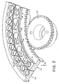
- Rotor 54 is as shown in Fig. 2 and as described in US-A-5,456,883, wherein each vessel-holding aperture 70 intersects a paired dump aperture 82 with a narrow passageway 83 connecting them. (Only one such pair is labeled, for clarity.) Each pair of apertures 70 and 82 is spaced away from the adjacent pair by a generally horizontal top surface 56, the utility of which will become apparent.
- the problem to be overcome by the invention is the vertical run-out of rotor 54 as it is rotated by gear 68. Such vertical run-out produces Z-axis vertical deviations, shown as double arrow 90.
- This vertical run-out becomes critical at certain critical stations disposed around the circumference of rotor 54, of which vessel-wash probe 78 is exemplary.
- a vessel C is rotated, arrow 100, into position under probe 78, the liquid already therein, including patient sample, is aspirated out by a pump 102, after the probe has been lowered into the vessel, arrow 104. Thereafter, wash water is supplied from reservoir 106 at least once, and a final wash is dispensed to an excessive level "A" in a rough dispensing step.
- a fine adjustment is then used in pump 102 to aspirate out to a known fixed level B, providing an accurate volume of soak liquid, for example, 230 ⁇ L, for soaking the reactive complexes inside the vessel C for an incubation period.
- this is corrected by providing a sensing probe and step wherein the empty or "tare" height of each vessel in the rotor, while in an aperture 70, is determined at the time of machine set-up, as the rotor rotates past a critical station (in this case, the vessel-wash station 78).
- a critical station in this case, the vessel-wash station 78.
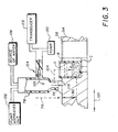
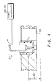
- That reference surface comprises either horizontal surface 56 immediately adjacent one or both sides of each vessel, as shown in Fig. 3, or the bottom of the empty vessel C itself as shown in Fig. 4, that is, a surface coincident with the vessel.
- vessel-wash probe 78 is outfitted with a source of air pressure 120 and a pressure transducer 122, connected via a one-way valve 124 that allows air flow in the direction of arrow 126, but no liquid flow opposite to arrow 126 back to source 120 or transducer 122.
- arrow 79 As probe 78 lowers towards surface 56, arrow 79, at a certain minimum distance from the surface the build-up of air will exceed a threshold value in transducer 122, indicating the presence of surface 56 at a known height, recorded in the analyzer's computer. The downward advance of probe 78 ceases at this point.
- This technique is more fully described in, for example, US-A-4,794,085, wherein the surface detected is a liquid.
- the height of surface 56 at either side of vessel C can be used, or an average of the two.
- the process is then repeated by rotating rotor 54, arrow 100, until the next vessel C (not shown) is brought into position adjacent probe 78, and the tare height-sensing process is then repeated. This is done for all the vessels at all the apertures 70, Fig. 2, in the entire annulus of rotor 54, because the amount of vertical run-out 90 at station 78 may vary for each such aperture 70.
- the computer registers what the tare height is for each such location, to adjust the depth the probe 78 must extend during vessel washing to provide an effective location B for tip surface 110 that gives the same volume of remaining soak liquid, regardless of the vertical run-out 90.
- probe 78 can extend down to the bottom of empty vessel C to detect the reference surface of the vessel, in a manner otherwise identical to the procedure described above for Fig. 3.
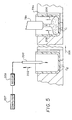
- Fig. 5 illustrates several features of the invention.
- a sensing probe independent of vessel wash probe 78 is used to determine the tare height, especially of the bottom of each empty vessel. Parts similar to those previously described bear the same reference numeral, to which the distinguishing suffix "a" is appended. It will be appreciated that this embodiment assumes the analyzer configuration is such that enough room is provided for the sensing probe to operate adjacent to the vessel-washing probe, by moving down into and up out of each vessel.
- rotor 54a carries vessels C 1 , C 2 , ... C n past a critical station, preferably the vessel aspirate-and-wash station using probe 78a, as before.
- probe 78a has no air pressure source or transducer connected to it. Instead, such are connected in the same way (not shown) to a sensor 200, which is a simple tube, mounted for vertical movement, arrow 202, much as is mounted probe 78a for vertical movement.
- both probe 78a and sensor 200 also pivot out away from vertical alignment with rotor 54a, when not in use, for example, via conventional mechanisms such as motor 209 and any suitable linkage, for sensor 200.
- the air delivered by sensor 200, arrow 204 is sufficient to detect the tare height of the empty vessel underneath it, for all such vessels C 1 , C 2 ... C n , during machine set-up, thus registering in the computer (for example, computer 207) the vertical run-out effect for that portion of the rotor supporting that particular vessel.
- any vessel thereafter can be moved so as to be washed, arrows 206, for example, vessel C 1 as shown, relying on the tare height determined by sensor 200 to cause an accurate soak volume to be left behind by probe 78a.
- the sensor of Fig. 5 can have an alternative, independent usage. That is, it is possible for probe 78a to also include its source of air pressure and transducer, as well as sensor 200. Each air pressure source and transducer can be separate from the other, or the same source and transducer can be used for both. In either case, the function of sensor 200 is to provide an independent check on the performance of probe 78a in its aspiration and re-soaking of each vessel. In such a case, sensor 200 need not be located anywhere near probe 78a (not shown) around the rotor circumference. In such a procedure, sensor 200 determines the tare height of each empty vessel during machine set-up, Fig. 5, as described above. Then, Fig.
- probe 78a which also has that capability. The reason for using sensor 200 in such a case to determine the liquid height, instead of probe 78a which also has that capability, is that it is not proper protocol to test the performance of an analyzer part (probe 78a) by using that very part being verified.
- the probe or sensor never contacts the surface that is to be detected, thus avoiding the risk of contamination.
Landscapes
- General Health & Medical Sciences (AREA)
- General Physics & Mathematics (AREA)
- Life Sciences & Earth Sciences (AREA)
- Chemical & Material Sciences (AREA)
- Analytical Chemistry (AREA)
- Biochemistry (AREA)
- Health & Medical Sciences (AREA)
- Immunology (AREA)
- Physics & Mathematics (AREA)
- Pathology (AREA)
- Automatic Analysis And Handling Materials Therefor (AREA)
- Measurement Of Levels Of Liquids Or Fluent Solid Materials (AREA)
- Length Measuring Devices With Unspecified Measuring Means (AREA)
- Filling Of Jars Or Cans And Processes For Cleaning And Sealing Jars (AREA)
- Centrifugal Separators (AREA)
Claims (3)
- Verfahren zum Bestimmen des einem tassenartigen Reaktionsgefäß (c) bekannter Ausmaße zugeführten Flüssigkeitsvolumens, bei dem:a) das Reaktionsgefäß (c) in einem bewegbaren Träger (54) angeordnet wird;b) der Träger (54) und das Reaktionsgefäß (c) bewegt werden, bis das Reaktionsgef"aß bei einer Sensierstation ist;c) die vertikale Position der Bodeninnenfläche des Reaktionsgefäßes (c) an der Sensierstation durch Zufuhr von Luft von einem mit einem Druckwandler (122) fluidal verbundenen Sensor (200) und durch Absenken des Sensors (200) in Richtung der Bodeninnenfläche des Reaktionsgefäßes (c) sensiert wird, bis der Druckwandler (122) eine Druckänderung erfaßt, wenn die von dem Sensor (200) zugeführte Luft auf die Bodeninnenfläche des Reaktionsgefäßes (c) trifft;d) der Träger (54) und das Reaktionsgefäß (c) zu einer Flüssigkeitszuftüustation bewegt werden;e) ein Flüssigkeitsvolumen in das Reaktionsgefäß (c) an der Flüssigkeitszuführstation zugeführt wird, wobei eine Luft-Flüssigkeits-Grenzfläche am oberen Ende des Volumens bereitgestellt wird;f) der Träger (54) und das Reaktionsgefäß (c) bewegt werden, bis das Reaktionsgefäß (c) zur Meßstation zurückgekehrt ist;g) die vertikale Position der Luft-Flüssigkeits-Crrenzfläche an der Meßstation durch Zuführen von Luft von dem Sensor (200) und durch Absenken des Sensors (200) in Richtung der Luft-Flüssigkeits-Grenzfläche sensiert wird, bis der Druckwandel (122) eine Druckänderung erfaßt, wenn die von dem Sensor (200) zugeführte Luft auf die Luft-Flüssigkeits-Grenzfläche stößt;h) die sensierte vertikale Position der Bodeninnenfläche und der Luft-Flüssigkeits-Grenzfläche des Reaktionsgefäßes (c) in eine Volumenmessung des Flüssigkeitsvolumens umgewandelt wird.
- Verfahren nach Anspruch 1, wobei der Sensor (200) eine strömungsmäßig mit einer Druckluftquelle (220) und mit dem Druckwandler (122) verbundene Luftdüse (200) ist.
- Vorrichtung zum Bestimmen des einem tassenartigen Reaktionsgefäß (c) bekannter Ausmaße zugeführten Flüssigkeitsvolumens umfassend:einen Rotorträger (54) mit darin angeordneten Öffnungen (70, 82), die mehrere tassenartige Reaktionsgefäße (c) tragen;eine Mehrzahl von Stationen, die um den Umfang des Rotors (54) angeordnet sind, einschließlich eine Waschstation; undeinen Motor (68), der den Rotozträger (54) und die Reaktionsgefäße (c) zwischen den Stationen dreht;dadurch gekennzeichnet, daß die Vorrichtung ferner einen von der Waschstation unabhängigen Sensor (200), der an einer anderen Position am Umfang des Rotors (54) angeordnet ist, wobei der Sensor (200) eine Druckluftquelle (120), eine Sonde zum Zuführen von Luftdruck nach unten in eines der Reaktionsgefäße (c) und einen Druckwandler (122) umfaßt, der mit der Sonde fluidal verbunden ist und zum Sensieren einer Änderung von Luftdruck aufgrund der Nachbarschaft zu einer Luft-Festkörper-Grenzfläche oder einer Luft-Flüssigkeits-Grenzfläche angeordnet ist; wobei der Sensor (200) zum Sensieren der Höhe einer Luft-Feststoff- und einer Luft-Flüssigkeits-Grenzfläche des Reaktionsgefäßes (c) ohne Berührung der Grenzfläche durch Absenken des Sensors (200) angeordnet ist, bis der Druckwandler (122) eine Änderung des Luftdruckes aufgrund der Nachbarschaft zu einer Luft-Feststoff- oder einer Luft-Flüssigkeits-Grenzfläche sensiert;
eine auf dem Rotorträger (54) angeordnete Einrichtung (209) zum Drehen des Sensors (200) über und in das Reaktionsgefäß (c); und
einen Computer (207) umfaßt, der dazu eingerichtet ist, die sensierten Höhen einer Luft-Feststoff-Grenzfläche des Reaktionsgefäßes (c) und einer Luft-Flüssigkeits-Grenzfläche des Reaktionsgefäßes (c), die durch den Sensor (200) gemessen sind, zu speichern und um die Höhen in eine Volumenmessung der Flüssigkeit in dem Reaktionsgefäß (c) umzuwandeln.
Applications Claiming Priority (4)
| Application Number | Priority Date | Filing Date | Title |
|---|---|---|---|
| US748306 | 1985-06-24 | ||
| US747878 | 1996-11-13 | ||
| US08/747,878 US5736403A (en) | 1996-11-13 | 1996-11-13 | Determining height variations around a rotor |
| US08/748,306 US5753512A (en) | 1996-11-13 | 1996-11-13 | Determining liquid volumes in cup-like vessels on a rotor having vertical deviations |
Publications (3)
| Publication Number | Publication Date |
|---|---|
| EP0843162A2 EP0843162A2 (de) | 1998-05-20 |
| EP0843162A3 EP0843162A3 (de) | 1999-04-21 |
| EP0843162B1 true EP0843162B1 (de) | 2007-03-21 |
Family
ID=27114838
Family Applications (1)
| Application Number | Title | Priority Date | Filing Date |
|---|---|---|---|
| EP97309076A Expired - Lifetime EP0843162B1 (de) | 1996-11-13 | 1997-11-12 | Bestimmung von Flüssigkeitsvolumen in becherförmigen Probenbehältern, die sich auf einem Rotor befinden, der ein Spiel in vertikaler Richtung aufweist |
Country Status (4)
| Country | Link |
|---|---|
| EP (1) | EP0843162B1 (de) |
| JP (1) | JP4611462B2 (de) |
| AT (1) | ATE357649T1 (de) |
| DE (1) | DE69737493T2 (de) |
Families Citing this family (4)
| Publication number | Priority date | Publication date | Assignee | Title |
|---|---|---|---|---|
| CN109724667B (zh) * | 2017-10-30 | 2022-08-05 | 诺信公司 | 容器内液体体积百分比的检测方法和系统以及具有该系统的分配器 |
| CN109975277B (zh) * | 2017-12-28 | 2024-08-13 | 深圳市新产业生物医学工程股份有限公司 | 化学发光检测仪及其检测方法 |
| CN112217362B (zh) * | 2020-09-25 | 2023-04-21 | 哈尔滨东北泵业有限责任公司 | 一种可自动校正转子不平衡的离心泵及其校正方法 |
| DE102021126081A1 (de) * | 2021-10-07 | 2023-04-13 | Hach Lange Gmbh | Analysevorbereitungs-Küvettenständereinheit |
Family Cites Families (13)
| Publication number | Priority date | Publication date | Assignee | Title |
|---|---|---|---|---|
| CA1252173A (en) * | 1984-07-19 | 1989-04-04 | Thomas C. Jessop | Apparatus and method for detecting liquid penetration by a container used for aspirating and dispensing the liquid |
| US4794085A (en) * | 1984-07-19 | 1988-12-27 | Eastman Kodak Company | Apparatus and method for detecting liquid penetration by a container used for aspirating and dispensing the liquid |
| CA1321940C (en) * | 1987-05-02 | 1993-09-07 | Teruaki Itoh | Apparatus for distributing sample liquid |
| JPH0446179Y2 (de) * | 1987-05-30 | 1992-10-29 | ||
| WO1991016675A1 (en) * | 1990-04-06 | 1991-10-31 | Applied Biosystems, Inc. | Automated molecular biology laboratory |
| US5133392A (en) * | 1991-04-10 | 1992-07-28 | Eastman Kodak Company | Liquid injection using container bottom sensing |
| JPH05180851A (ja) * | 1991-12-03 | 1993-07-23 | Hitachi Ltd | 自動分析装置用微量検体のサンプリング方法 |
| EP0555739B1 (de) * | 1992-02-13 | 1998-05-20 | F. Hoffmann-La Roche Ag | Automatische Pipettiervorrichtung |
| US5244633A (en) * | 1992-05-22 | 1993-09-14 | Eastman Kodak Company | Analyzer incubator with plural independently driven rings supporting cuvettes |
| US5270210A (en) * | 1992-07-16 | 1993-12-14 | Schiapparelli Biosystems, Inc. | Capacitive sensing system and wash/alignment station for a chemical analyzer |
| JPH06191501A (ja) * | 1992-12-07 | 1994-07-12 | Oval Corp | 充填装置 |
| JPH07239335A (ja) * | 1994-02-28 | 1995-09-12 | Hitachi Ltd | 自動分析装置 |
| JP3485664B2 (ja) * | 1995-01-19 | 2004-01-13 | 富士写真フイルム株式会社 | サンプリング装置 |
-
1997
- 1997-11-12 EP EP97309076A patent/EP0843162B1/de not_active Expired - Lifetime
- 1997-11-12 JP JP31061697A patent/JP4611462B2/ja not_active Expired - Fee Related
- 1997-11-12 AT AT97309076T patent/ATE357649T1/de not_active IP Right Cessation
- 1997-11-12 DE DE69737493T patent/DE69737493T2/de not_active Expired - Lifetime
Also Published As
| Publication number | Publication date |
|---|---|
| EP0843162A2 (de) | 1998-05-20 |
| EP0843162A3 (de) | 1999-04-21 |
| JP4611462B2 (ja) | 2011-01-12 |
| JPH10153467A (ja) | 1998-06-09 |
| DE69737493D1 (de) | 2007-05-03 |
| DE69737493T2 (de) | 2007-12-06 |
| ATE357649T1 (de) | 2007-04-15 |
Similar Documents
| Publication | Publication Date | Title |
|---|---|---|
| US5753512A (en) | Determining liquid volumes in cup-like vessels on a rotor having vertical deviations | |
| US8475740B2 (en) | Liquid dispensing apparatus | |
| US6267927B1 (en) | Apparatus for performing laboratory tests automatically | |
| US5736403A (en) | Determining height variations around a rotor | |
| EP0482135B1 (de) | Flüssigkeitsabgabevorrichtung mit positionsgeber | |
| EP2755038B1 (de) | Automatisches Analysegerät und Verfahren zur Verwendung in einem automatischen Analysegerät | |
| EP2525230A1 (de) | Automatisches analysegerät | |
| EP0843162A2 (de) | Bestimmung von Flüssigkeitsvolumen in Probenbehälter, die auf einem Rotor mit senkrechter Abweichung liegen | |
| EP1209471B1 (de) | Verfahren zur Bestimmung der Ansaugung einer Flüssigkeit | |
| JP7629990B2 (ja) | 多点フィルタリング液位検出方法および装置 | |
| JP7061686B2 (ja) | 自動分析装置 | |
| JP2000338115A (ja) | 液体残量検出装置 | |
| JP2021124443A (ja) | 自動分析装置 | |
| WO2020195500A1 (ja) | 自動分析装置 | |
| JPH10291593A (ja) | 給油装置 | |
| CN118401842A (zh) | 自动分析装置、分注方法 | |
| JPH11271320A (ja) | 自動分注装置 | |
| CN210071849U (zh) | 用于全自动生化分析仪水浴盘的液面高度测量系统 | |
| CN223910319U (zh) | 一种量杯加量提示辅助装置 | |
| CN218822657U (zh) | 智能超声波无阀水表检测用的注水机构 | |
| JPH07174766A (ja) | 自動化学分析装置における試料サンプリング装置 | |
| JPH042964A (ja) | 医用液状検体検査装置 | |
| CN119175011A (zh) | 一种稀释液加注装置及方法 | |
| CN114894274A (zh) | 计量器具容量校准设备 | |
| JPH08313540A (ja) | 臨床用生化学自動分析装置 |
Legal Events
| Date | Code | Title | Description |
|---|---|---|---|
| PUAI | Public reference made under article 153(3) epc to a published international application that has entered the european phase |
Free format text: ORIGINAL CODE: 0009012 |
|
| AK | Designated contracting states |
Kind code of ref document: A2 Designated state(s): AT BE CH DE DK ES FI FR GB GR IE IT LI LU MC NL PT SE |
|
| AX | Request for extension of the european patent |
Free format text: AL;LT;LV;MK;RO;SI |
|
| PUAL | Search report despatched |
Free format text: ORIGINAL CODE: 0009013 |
|
| AK | Designated contracting states |
Kind code of ref document: A3 Designated state(s): AT BE CH DE DK ES FI FR GB GR IE IT LI LU MC NL PT SE |
|
| AX | Request for extension of the european patent |
Free format text: AL;LT;LV;MK;RO;SI |
|
| 17P | Request for examination filed |
Effective date: 19991001 |
|
| AKX | Designation fees paid |
Free format text: AT BE CH DE DK ES FI FR GB GR IE IT LI LU MC NL PT SE |
|
| 17Q | First examination report despatched |
Effective date: 20040518 |
|
| RTI1 | Title (correction) |
Free format text: DETERMINING LIQUID VOLUMES IN CUP-LIKE VESSELS BEING POSITIONED ON A ROTOR HAVING A RUN-OUT IN VERTICAL DIRECTION |
|
| GRAP | Despatch of communication of intention to grant a patent |
Free format text: ORIGINAL CODE: EPIDOSNIGR1 |
|
| GRAS | Grant fee paid |
Free format text: ORIGINAL CODE: EPIDOSNIGR3 |
|
| GRAA | (expected) grant |
Free format text: ORIGINAL CODE: 0009210 |
|
| RAP1 | Party data changed (applicant data changed or rights of an application transferred) |
Owner name: ORTHO-CLINICAL DIAGNOSTICS, INC. |
|
| AK | Designated contracting states |
Kind code of ref document: B1 Designated state(s): AT BE CH DE DK ES FI FR GB GR IE IT LI LU MC NL PT SE |
|
| PG25 | Lapsed in a contracting state [announced via postgrant information from national office to epo] |
Ref country code: NL Free format text: LAPSE BECAUSE OF FAILURE TO SUBMIT A TRANSLATION OF THE DESCRIPTION OR TO PAY THE FEE WITHIN THE PRESCRIBED TIME-LIMIT Effective date: 20070321 Ref country code: FI Free format text: LAPSE BECAUSE OF FAILURE TO SUBMIT A TRANSLATION OF THE DESCRIPTION OR TO PAY THE FEE WITHIN THE PRESCRIBED TIME-LIMIT Effective date: 20070321 Ref country code: BE Free format text: LAPSE BECAUSE OF FAILURE TO SUBMIT A TRANSLATION OF THE DESCRIPTION OR TO PAY THE FEE WITHIN THE PRESCRIBED TIME-LIMIT Effective date: 20070321 Ref country code: AT Free format text: LAPSE BECAUSE OF FAILURE TO SUBMIT A TRANSLATION OF THE DESCRIPTION OR TO PAY THE FEE WITHIN THE PRESCRIBED TIME-LIMIT Effective date: 20070321 |
|
| REG | Reference to a national code |
Ref country code: GB Ref legal event code: FG4D |
|
| REG | Reference to a national code |
Ref country code: CH Ref legal event code: EP |
|
| REF | Corresponds to: |
Ref document number: 69737493 Country of ref document: DE Date of ref document: 20070503 Kind code of ref document: P |
|
| REG | Reference to a national code |
Ref country code: IE Ref legal event code: FG4D |
|
| REG | Reference to a national code |
Ref country code: CH Ref legal event code: NV Representative=s name: E. BLUM & CO. AG PATENT- UND MARKENANWAELTE VSP |
|
| PG25 | Lapsed in a contracting state [announced via postgrant information from national office to epo] |
Ref country code: SE Free format text: LAPSE BECAUSE OF FAILURE TO SUBMIT A TRANSLATION OF THE DESCRIPTION OR TO PAY THE FEE WITHIN THE PRESCRIBED TIME-LIMIT Effective date: 20070621 |
|
| PG25 | Lapsed in a contracting state [announced via postgrant information from national office to epo] |
Ref country code: ES Free format text: LAPSE BECAUSE OF FAILURE TO SUBMIT A TRANSLATION OF THE DESCRIPTION OR TO PAY THE FEE WITHIN THE PRESCRIBED TIME-LIMIT Effective date: 20070702 |
|
| PG25 | Lapsed in a contracting state [announced via postgrant information from national office to epo] |
Ref country code: PT Free format text: LAPSE BECAUSE OF FAILURE TO SUBMIT A TRANSLATION OF THE DESCRIPTION OR TO PAY THE FEE WITHIN THE PRESCRIBED TIME-LIMIT Effective date: 20070821 |
|
| NLV1 | Nl: lapsed or annulled due to failure to fulfill the requirements of art. 29p and 29m of the patents act | ||
| PLBE | No opposition filed within time limit |
Free format text: ORIGINAL CODE: 0009261 |
|
| STAA | Information on the status of an ep patent application or granted ep patent |
Free format text: STATUS: NO OPPOSITION FILED WITHIN TIME LIMIT |
|
| PG25 | Lapsed in a contracting state [announced via postgrant information from national office to epo] |
Ref country code: DK Free format text: LAPSE BECAUSE OF FAILURE TO SUBMIT A TRANSLATION OF THE DESCRIPTION OR TO PAY THE FEE WITHIN THE PRESCRIBED TIME-LIMIT Effective date: 20070321 |
|
| 26N | No opposition filed |
Effective date: 20071227 |
|
| PG25 | Lapsed in a contracting state [announced via postgrant information from national office to epo] |
Ref country code: GR Free format text: LAPSE BECAUSE OF FAILURE TO SUBMIT A TRANSLATION OF THE DESCRIPTION OR TO PAY THE FEE WITHIN THE PRESCRIBED TIME-LIMIT Effective date: 20070622 |
|
| PG25 | Lapsed in a contracting state [announced via postgrant information from national office to epo] |
Ref country code: MC Free format text: LAPSE BECAUSE OF NON-PAYMENT OF DUE FEES Effective date: 20071130 |
|
| PG25 | Lapsed in a contracting state [announced via postgrant information from national office to epo] |
Ref country code: IE Free format text: LAPSE BECAUSE OF NON-PAYMENT OF DUE FEES Effective date: 20071112 |
|
| PG25 | Lapsed in a contracting state [announced via postgrant information from national office to epo] |
Ref country code: LU Free format text: LAPSE BECAUSE OF NON-PAYMENT OF DUE FEES Effective date: 20071112 |
|
| REG | Reference to a national code |
Ref country code: FR Ref legal event code: PLFP Year of fee payment: 19 |
|
| PGFP | Annual fee paid to national office [announced via postgrant information from national office to epo] |
Ref country code: IT Payment date: 20151124 Year of fee payment: 19 |
|
| REG | Reference to a national code |
Ref country code: FR Ref legal event code: PLFP Year of fee payment: 20 |
|
| PGFP | Annual fee paid to national office [announced via postgrant information from national office to epo] |
Ref country code: DE Payment date: 20161108 Year of fee payment: 20 Ref country code: CH Payment date: 20161115 Year of fee payment: 20 Ref country code: FR Payment date: 20161014 Year of fee payment: 20 Ref country code: GB Payment date: 20161109 Year of fee payment: 20 |
|
| PG25 | Lapsed in a contracting state [announced via postgrant information from national office to epo] |
Ref country code: IT Free format text: LAPSE BECAUSE OF NON-PAYMENT OF DUE FEES Effective date: 20161112 |
|
| REG | Reference to a national code |
Ref country code: DE Ref legal event code: R071 Ref document number: 69737493 Country of ref document: DE |
|
| REG | Reference to a national code |
Ref country code: CH Ref legal event code: PL |
|
| REG | Reference to a national code |
Ref country code: GB Ref legal event code: PE20 Expiry date: 20171111 |
|
| PG25 | Lapsed in a contracting state [announced via postgrant information from national office to epo] |
Ref country code: GB Free format text: LAPSE BECAUSE OF EXPIRATION OF PROTECTION Effective date: 20171111 |