EP0843321A2 - Câble avec gain métallique, résistant à la chaleur, pour capteur - Google Patents
Câble avec gain métallique, résistant à la chaleur, pour capteur Download PDFInfo
- Publication number
- EP0843321A2 EP0843321A2 EP97120211A EP97120211A EP0843321A2 EP 0843321 A2 EP0843321 A2 EP 0843321A2 EP 97120211 A EP97120211 A EP 97120211A EP 97120211 A EP97120211 A EP 97120211A EP 0843321 A2 EP0843321 A2 EP 0843321A2
- Authority
- EP
- European Patent Office
- Prior art keywords
- sheathing tube
- heat
- tube
- ventilation
- conductors
- Prior art date
- Legal status (The legal status is an assumption and is not a legal conclusion. Google has not performed a legal analysis and makes no representation as to the accuracy of the status listed.)
- Granted
Links
- 239000004020 conductor Substances 0.000 claims abstract description 115
- 238000009423 ventilation Methods 0.000 claims abstract description 82
- 239000000843 powder Substances 0.000 claims abstract description 29
- 239000001301 oxygen Substances 0.000 claims description 49
- 229910052760 oxygen Inorganic materials 0.000 claims description 49
- QVGXLLKOCUKJST-UHFFFAOYSA-N atomic oxygen Chemical compound [O] QVGXLLKOCUKJST-UHFFFAOYSA-N 0.000 claims description 47
- 239000000919 ceramic Substances 0.000 claims description 40
- 239000002184 metal Substances 0.000 claims description 36
- 229910052751 metal Inorganic materials 0.000 claims description 36
- 239000007789 gas Substances 0.000 claims description 30
- 239000000835 fiber Substances 0.000 claims description 28
- 230000000712 assembly Effects 0.000 claims description 12
- 238000000429 assembly Methods 0.000 claims description 12
- 238000003466 welding Methods 0.000 claims description 3
- CPLXHLVBOLITMK-UHFFFAOYSA-N Magnesium oxide Chemical compound [Mg]=O CPLXHLVBOLITMK-UHFFFAOYSA-N 0.000 abstract description 58
- 239000000395 magnesium oxide Substances 0.000 abstract description 29
- 229910001220 stainless steel Inorganic materials 0.000 abstract description 12
- 239000010935 stainless steel Substances 0.000 abstract description 12
- PXHVJJICTQNCMI-UHFFFAOYSA-N Nickel Chemical compound [Ni] PXHVJJICTQNCMI-UHFFFAOYSA-N 0.000 description 15
- PNEYBMLMFCGWSK-UHFFFAOYSA-N aluminium oxide Inorganic materials [O-2].[O-2].[O-2].[Al+3].[Al+3] PNEYBMLMFCGWSK-UHFFFAOYSA-N 0.000 description 5
- 238000009413 insulation Methods 0.000 description 5
- 229910052759 nickel Inorganic materials 0.000 description 5
- 230000001681 protective effect Effects 0.000 description 5
- 239000000356 contaminant Substances 0.000 description 4
- 238000005516 engineering process Methods 0.000 description 4
- 238000000034 method Methods 0.000 description 4
- VYPSYNLAJGMNEJ-UHFFFAOYSA-N Silicium dioxide Chemical compound O=[Si]=O VYPSYNLAJGMNEJ-UHFFFAOYSA-N 0.000 description 3
- 239000011230 binding agent Substances 0.000 description 3
- 238000010438 heat treatment Methods 0.000 description 3
- 230000001788 irregular Effects 0.000 description 3
- 238000005192 partition Methods 0.000 description 3
- 230000035699 permeability Effects 0.000 description 3
- BASFCYQUMIYNBI-UHFFFAOYSA-N platinum Chemical compound [Pt] BASFCYQUMIYNBI-UHFFFAOYSA-N 0.000 description 3
- 239000012260 resinous material Substances 0.000 description 3
- 238000009941 weaving Methods 0.000 description 3
- 239000000377 silicon dioxide Substances 0.000 description 2
- 238000003915 air pollution Methods 0.000 description 1
- 239000004568 cement Substances 0.000 description 1
- 238000010622 cold drawing Methods 0.000 description 1
- 238000002485 combustion reaction Methods 0.000 description 1
- 238000004891 communication Methods 0.000 description 1
- 238000001514 detection method Methods 0.000 description 1
- 230000000694 effects Effects 0.000 description 1
- 238000001125 extrusion Methods 0.000 description 1
- 239000000446 fuel Substances 0.000 description 1
- 239000011521 glass Substances 0.000 description 1
- 238000009434 installation Methods 0.000 description 1
- 239000012212 insulator Substances 0.000 description 1
- 238000012986 modification Methods 0.000 description 1
- 230000004048 modification Effects 0.000 description 1
- 230000002093 peripheral effect Effects 0.000 description 1
- 229910052697 platinum Inorganic materials 0.000 description 1
- 239000011148 porous material Substances 0.000 description 1
- 230000000717 retained effect Effects 0.000 description 1
- 239000007787 solid Substances 0.000 description 1
- 239000007784 solid electrolyte Substances 0.000 description 1
- 239000000126 substance Substances 0.000 description 1
- XLYOFNOQVPJJNP-UHFFFAOYSA-N water Substances O XLYOFNOQVPJJNP-UHFFFAOYSA-N 0.000 description 1
Images



Classifications
-
- G—PHYSICS
- G01—MEASURING; TESTING
- G01N—INVESTIGATING OR ANALYSING MATERIALS BY DETERMINING THEIR CHEMICAL OR PHYSICAL PROPERTIES
- G01N27/00—Investigating or analysing materials by the use of electric, electrochemical, or magnetic means
- G01N27/26—Investigating or analysing materials by the use of electric, electrochemical, or magnetic means by investigating electrochemical variables; by using electrolysis or electrophoresis
- G01N27/403—Cells and electrode assemblies
- G01N27/406—Cells and probes with solid electrolytes
- G01N27/407—Cells and probes with solid electrolytes for investigating or analysing gases
- G01N27/4077—Means for protecting the electrolyte or the electrodes
Definitions
- the present invention relates to a heat-resisting metal-sheathed cable for a sensor such as an oxygen sensor or thermistor which is disposed in a high temperature place in an automobile or the like.
- An oxygen concentration cell type oxygen sensor is heretofore known as a sensor for detecting an air-fuel ratio of an internal combustion engine such as an automotive engine.
- the oxygen sensor includes a pair of porous electrodes disposed on the opposite sides of a partition wall member made of an oxygen ion conductive solid electrolyte and is constructed so as to put one of the porous electrodes into contact with the reference gas and the other into contact with the cured gas (i.e., gas to be measured) such that the oxygen concentration is measured based on the electromotive force cell across the electrodes.
- the reference gas is accurate. For example, in case there occurs ingress of gasoline, water or the like into a chamber containing the reference gas, the reference gas is contaminated to disable accurate detection. For this reason, it has heretofore been practiced to provide the chamber with an air-tight wall surrounding the reference gas for thereby preventing ingress of contaminants into the chamber.
- the above described technology still has a difficulty in preventing the ingress of contaminants completely, so it has been proposed to provide the chamber with an atmospheric air introducing hole which is devised to make it difficult for the contaminants to intrude therethrough into the chamber such that the chamber can be ventilated so as to contain the normal atmospheric air even if the contaminants intrude into the chamber a little.
- Japanese utility model provisional publication No. 56-4852 such a technology of using a covered harness having an insulation covering made of a resinous material for fetching or output of signal, providing the harness with a hollow portion at the axial center thereof and using the hollow portion as a ventilation hole for passage or conduction of the atmospheric air.
- a novel and improved heat-resisting metal-sheathed cable for a sensor which comprises a sheathing tube made of heat-resisting metal, at least one conductor and at least one ventilation tube disposed at a predetermined interval within the sheathing tube, the ventilation tube being made of heat-resisting metal, and a mass of insulating powder filled in the sheathing tube in a way as to surround the conductor and the ventilation tube.
- the filling of the insulation powder within the sheathing tube makes it possible to attain a sufficient heat-resisting ability and a sufficient insulating ability, while making it possible to attain the ventilating ability by means of the ventilation tubes made of heat-resisting metal and disposed within the mass of insulating powder for the purpose of keeping good the reference gas of the oxygen sensor for instance.
- a heat-resisting metal-sheathed cable for a sensor which comprises a sheathing tube made of heat-resisting metal, a pair of conductors and a pair of ventilation tubes disposed at predetermined intervals within the sheathing tube, the ventilation tube being made of heat-resisting metal, and a mass of insulating powder filled in the sheathing tube in a way as to surround the conductors and the ventilation tubes, wherein the conductors are respectively positioned at two of four corners of a square and the ventilation tubes are respectively positioned at remaining two of said four corners when observed in a cross sectional view of the sheathing tube.
- the inner diameter of the sheathing tube made of heat-resisting metal is generally so small, it never occurs a short circuit between the conductors or the like fault since the pair of conductors and the pair of ventilation tubes are disposed so as to be position at four corners of a square, i.e., disposed so as to be distant from each other as much as possible according to the present invention.
- a cable as set forth in the second aspect, wherein the conductors and the ventilation tubes are disposed diagonally, respectively.
- the conductors are disposed at diagonal positions, i.e., at positions most distant from each other, so it never occurs a short circuit between the conductors or the like fault. This is because the conductors are disposed so as to oppose diametrically each other, particularly when the ventilation tubes have a large diameter.
- a heat-resisting metal-sheathed cable for a sensor which comprises a sheathing tube made of heat-resisting metal, a ventilation tube made of heat-resisting metal disposed concentrically within the sheathing tube, a plurality of conductors disposed at predetermined intervals within the sheathing tube and around the ventilation tube, and a mass of insulating powder filled in the sheathing tube in a way as to surround the conductors and the ventilation tube.
- the arrangement of disposing the ventilation tube concentrically within the sheathing tube enables to set the diameter of the ventilation tube larger. Accordingly, sufficient ventilation can be attained even when a number of conductors are used in the cable.
- a cable according to the fourth aspect wherein the conductors are respectively positioned at four corners of a square when observed in a cross sectional view of the sheathing tube.
- a heat-resisting metal-sheathed cable for a sensor which comprises an outer sheathing tube made of heat-resisting metal, an inner sheathing tube made of heat-resisting metal and disposed within the outer sheathing tube in a way as to provide therebetween a predetermined gap constituting a ventilation passage, at least one conductor disposed within the inner sheathing tube, and a mass of insulating powder filled in the inner sheathing tube in a way as to surround the conductor.
- the space or passage for ventilation is shaped annular in cross section, so there is produced an advantage that the space can be made larger.
- a cable according to the sixth aspect wherein the outer and inner sheathing tubes are secured to each other with welding.
- the outer and inner sheathing tubes are assuredly held fixed or stationary to each other, thus making it possible to prevent the outer and inner sheathing tubes from striking against each other due to vibrations or the like to cause disconnection of the conductors or a short circuit between the conductors within the inner sheathing tube and therefore making it possible to improve the reliability of the cable.
- a heat-resisting metal-sheathed cable for a sensor which comprises a sheathing tube made of heat-resisting metal, at least one conductor disposed within the sheathing tube, and a mass of ceramic fibers disposed within the sheathing tube and surrounding the conductor.
- a mass or layer of ceramic fibers having a permeability is a ceramic yarn, and a number of pores and spaces between the ceramic fibers are used as a ventilation passage.
- a heat-resisting metal-sheathed cable for a sensor which comprises a sheathing tube made of heat-resisting metal, a plurality of conductors disposed within the sheathing tube, a plurality of first masses of ceramic fibers disposed within the sheathing tube and surrounding the conductors to constitute insulated conductor assemblies, respectively, the insulated conductor assemblies being twisted into a bundle, and a second mass of ceramic fibers disposed within the sheathing tube and surrounding the bundle. Accordingly, even in the case a plurality of conductors are disposed within a sheathing tube, it never occurs a short circuit between the conductors.
- the bundle has an outer surface having gentle undulations or irregularities.
- the bundle of conductor assemblies can be firmly held within the sheathing tube.
- tubes made of stainless steel such as SUS310S, SUS304 or SUS316 according to Japanese Industrial Standards can be used.
- insulating powder magnesia powder, alumina powder or the like can be used.
- the outer diameter of the sheathing tube can be within the range from 3.0 mm to 3.2 mm and the thickness thereof can be within the range from 0.3 mm to 0.6 mm.
- the outer diameter of the ventilation tube can not be determined simply since it varies largely depending upon how the ventilation tube is disposed within the sheathing tube but such an outer diameter is desirable that enables to attain a ventilation passage having a cross sectional area ranging fro 0.2 to 3 mm 2 .
- the outer diameter of the conductors is desirable to be within the range from about 0.4 to 0.6 mm on consideration of the strength and the demand for the smaller diameter of the cable.
- ceramic fibers fibers having heat resistance and insulation such as alumina fiber, silica fiber or alumina-silica fiber can be used.
- a ceramic yarn can be formed from ceramic fibers which are woven or twisted together. The diameter of the ceramic fibers forming such a ceramic yarn is desired to be within the range from 5 to 10 ⁇ m from the point of view of the easiness in weaving, the strength, etc.
- the above structure is effective for solving the above noted problems inherent in the prior art cable for sensors that is used under a high temperature condition.
- a heat-resisting metal-sheathed cable (hereinafter referred to simply as metal-sheathed cable) according to the first embodiment of the present invention is for use with one of oxygen sensors adapted for installation on an automotive vehicle exhaust pipe or manifold for instance, particularly an oxygen sensor of the type that requires a reference gas.
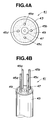
- a metal-sheathed cable 41 includes a metallic sheathing tube 43 constituting an outer protective wall or covering of the cable 41, four conductors 45a to 45d and one metallic ventilation tube 47 disposed within the sheathing tube 43, and a mass 49 of insulating magnesia powder packed and compressed, i.e., filled in the sheathing tube 43.
- the ventilation tube can otherwise be constructed so as to double as a conductor.
- the sheathing tube 43 is made of stainless steel (SUS304 according to Japanese Industrial Standards) and is 3.2 mm in outer diameter and 0.5 mm thick.
- the conductors 45a to 45d are made of nickel (Ni) and each consist of a single wire of 0.23 mm in outer diameter.
- the ventilation tube 47 is made of stainless steel (SUS304) and is 0.78 mm in outer diameter and 0.23 mm in inner diameter.
- the ventilation tube 47 is disposed so as to be concentric with the sheathing tube 43, and the four conductors 45a to 45d are disposed around the ventilation tube 47 in such a way as to be positioned at four corners of a square when observed in an elevation or cross sectional view of the metal-sheathed cable 41.
- magnesia powder is mixed with a binder and extruded into a bar of a predetermined size (8 cm in length) by an extruding machine to form a magnesia bar having holes or openings through which the ventilation tubes 47 and the conductors 45a to 45d can pass.
- the magnesia bar can be extended by being added with another magnesia bar for use in a longer sheathing tube, i.e., a longer cable.
- the extruded magnesia bar is provisionally sintered.
- magnesia bar are passed the conductors 45a to 45d and the ventilation tube 47, and the outer circumferential periphery of the magnesia bar is covered by the sheathing tube 43.
- the sheathing tube 43 is cold drawn so as to reduce in diameter.
- the cold drawn product is annealed within a vacuum furnace, whereby to complete the metal-sheathed cable 41.
- the metal-sheathed cable 43 is constructed so as to have the ventilation tube 47 at the center of or concentric with the sheathing tube 43 and the conductors 45a to 45d around the ventilation tube 47, so even in the case a number of conductors 45a to 45d are disposed within a limited space they can be distant from each other so as to make it possible to produce an advantage of a short circuit being hardly caused. Further, since the ventilation tube 47 is disposed at the center of or concentric with the sheathing tube 43, the ventilation tube 47 can be made larger in diameter considerably, thus making it possible to attain a better ventilation ability.
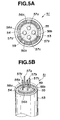
- a metal-sheathed cable 51 includes an outer metallic sheathing tube 53 constituting an outer protective wall or covering of the cable 51, an inner metallic sheathing tube 55 constituting an inner protective wall of the cable 55 disposed within the sheathing tube 53, four conductors 57a to 57d disposed within the inner sheathing tube 53, and a mass 59 of insulating magnesia powder packed and compressed, i.e., filled in the inner sheathing tube 53 and around the conductors 57a to 57d.
- Two of the four conductors are provided for fetching or taking out of the output of the sensor 3 and the remaining two are connected to the heater (not shown) for heating the sensor element 5.
- the above described outer sheathing tube 53 is made of stainless steel (SUS316 according to Japanese Industrial Standards) and is 3.2 mm in outer diameter and 0.5 mm thick.
- the inner sheathing tube 55 is made of stainless steel (SUS316) and is 3.2 mm in outer diameter and 0.3 mm thick.
- the conductors 57a to 57d are made of nickel (Ni) and each consist of a single wire of 0.4 mm in diameter.
- the outer sheathing tube 53 and the inner sheathing tube 55 are disposed concentric with each other while providing a small clearance or gap (about 0.35 mm) therebetween and welded together at end portions (i.e., the hatched portions in Fig. 5A) 56a and 56b in such a manner that the above described clearance or gap is retained.
- an annular passage 54 having open end portions 58a and 58b disposed on horizontally opposed sides in Fig. 5A.
- the conductors 57a to 57d are disposed within the inner sheathing tube 55 in such a way as to be respectively positioned at four corners of a square when observed in an elevation or cross sectional view of the cable 51.
- the method of producing the metal-sheathed cable 51 will be described briefly though partially similar to that described with respect to the first embodiment.
- magnesia powder is mixed with a binder and extruded into a bar of a predetermined size by an extruding machine to form a magnesia bar having holes or openings through which the conductors 57a to 57d can pass.
- the extruded magnesia bar is dried and provisionally sintered.
- magnesia bar are passed the conductors 57a to 57d, and the outer circumferential periphery of the magnesia bar is covered by the inner sheathing tube 55.
- the inner sheathing tube 55 is cold drawn so as to reduce in diameter.
- the cold drawn product is annealed within a vacuum furnace.
- the inner sheathing tube 55 is disposed within the outer sheathing tube 53 and held stationery relative to same in a way as to provide a predetermined annular clearance or gap therebetween by means of a jig or the like. Under such a condition of the inner sheathing tube 55 being held stationary relative to the outer sheathing tube 53, portions of each end of the inner sheathing tube 55 are welded to corresponding portion of each end of the sheathing tube 53, whereby to complete the metal-sheathed cable 51.
- the metal-sheathed cable 51 of this embodiment has the inner sheathing tube 55 which is disposed within the outer sheathing tube 53 in such a manner as to form the ventilation passage 54 of an annular cross section, so even in the case of the insulation structure using the mass 59 of insulating magnesia which is packed and compressed, i.e., filled in the inner sheathing tube 55 a ventilation passage for introducing a reference gas into the reference oxygen chamber of the oxygen sensor 3 can be formed within the metal-sheathed cable 51 with ease and assuredness.
- annular cross sectional passage 54 having a large cross sectional area can be formed between the inner and outer sheathing tubes 55 and 53, thus making it possible to introduce the reference gas are easily.
- the metal-sheathed cable 61 of this embodiment includes a metallic sheathing tube 63 constituting an outer protective wall or covering of the cable 61, four conductors 67a to 67d disposed within the sheathing tube 63, first masses of ceramic fibers or first ceramic yarns 65a to 65d covering or surrounding the conductors 67a to 67d, respectively and a second mass of ceramic fibers or second ceramic yarn 69 covering or surrounding the first ceramic yarns 65a to 65d.
- Two of the four conductors are for outputting of the sensor 3, and the remaining two of the conductors are connected to the heater (not shown) for heating the sensor element 5.
- the sheathing tube 63 is made of stainless steel (SUS310S according to the Japanese Industrial Standards) and is 3.2 mm in outer diameter and 0.5 mm thick.
- the conductors 67a to 67d are made of nickel (Ni) and each consist of a single wire of 0.45 mm in diameter.
- the first ceramic yarns 65a to 65d are tubular fibrous bodies formed from woven ceramic fibers (e.g., alumina fiber of 7 ⁇ m thick), so the conductors 67a to 67d are covered by the fibrous bodies to constitute assemblies of conductors 67a to 67d and ceramic yarns 65a to 65d, i.e., insulated conductor assemblies.
- the four insulated conductor assemblies are twisted into a bundle having an irregular or rugged outer surface, and the outer periphery of the bundle is covered by the second ceramic yarn 69 which is a tubular fibrous body formed similarly to the first ceramic yarns 65a to 65d.
- the first ceramic yarns 65a to 65d and the second ceramic yarn 69 of ceramic are shown by crosshatching.
- the ceramic yarns 65a to 65d are respectively formed around the conductors 67a to 67d made of nickel (Ni) by weaving of a long-fiber of alumina of 7 ⁇ m thick for thereby forming the above described insulated conductor assemblies.
- the insulated conductor assemblies are twisted into a bundle, and around the bundle is formed the second ceramic yarn 69 by weaving of a long-fiber of alumina for thereby forming an insulated bundle of conductors.
- the insulated bundle of conductors are disposed within the sheathing tube 63 of 4.0 mm in diameter and 0.4 mm thick and processed by a rotary swaging machine in such a manner that the outer diameter of the assembly is reduced to 3.2 mm, whereby to complete the metal-sheathed cable 61.
- the metal-sheathed cable 61 of this embodiment has within the sheathing tube 63 the conductors 65a to 65d which are covered by the first ceramic yarns 67a to 67d and the second ceramic yarn 69, so the conductors 65a to 65d can be held insulated from each other and from the sheathing tube 63, while a ventilation passage for introduction or conduction of the reference gas into the reference oxygen chamber of the oxygen sensor can be formed with ease within the metal-sheathed cable by utilizing the space between the fibers of the first ceramic yarns 65a to 65d and the second ceramic yarn 69.
- the four conductors 67a to 67d are twisted into a bundle having an irregular or rugged outer surface, so by the effect of such an irregular or rugged surface it becomes possible to prevent the bundle of the conductors 67a to 67d from moving out of place within the sheathing tube 63 or being removed from the sheathing tube 63.
Landscapes
- Chemical & Material Sciences (AREA)
- Life Sciences & Earth Sciences (AREA)
- Health & Medical Sciences (AREA)
- Biochemistry (AREA)
- General Physics & Mathematics (AREA)
- Electrochemistry (AREA)
- Physics & Mathematics (AREA)
- Analytical Chemistry (AREA)
- Molecular Biology (AREA)
- General Health & Medical Sciences (AREA)
- Chemical Kinetics & Catalysis (AREA)
- Immunology (AREA)
- Pathology (AREA)
- Measuring Oxygen Concentration In Cells (AREA)
- Insulated Conductors (AREA)
- Arrangements For Transmission Of Measured Signals (AREA)
- Measuring Temperature Or Quantity Of Heat (AREA)
Applications Claiming Priority (3)
| Application Number | Priority Date | Filing Date | Title |
|---|---|---|---|
| JP30649096A JP3532366B2 (ja) | 1996-11-18 | 1996-11-18 | センサ用耐熱金属シースリード線 |
| JP30649096 | 1996-11-18 | ||
| JP306490/96 | 1996-11-18 |
Publications (3)
| Publication Number | Publication Date |
|---|---|
| EP0843321A2 true EP0843321A2 (fr) | 1998-05-20 |
| EP0843321A3 EP0843321A3 (fr) | 1999-01-13 |
| EP0843321B1 EP0843321B1 (fr) | 2003-04-23 |
Family
ID=17957654
Family Applications (1)
| Application Number | Title | Priority Date | Filing Date |
|---|---|---|---|
| EP97120211A Expired - Lifetime EP0843321B1 (fr) | 1996-11-18 | 1997-11-18 | Câble avec gaine métallique, résistant à la chaleur, pour capteur |
Country Status (4)
| Country | Link |
|---|---|
| US (1) | US6188025B1 (fr) |
| EP (1) | EP0843321B1 (fr) |
| JP (1) | JP3532366B2 (fr) |
| DE (1) | DE69721185T2 (fr) |
Cited By (2)
| Publication number | Priority date | Publication date | Assignee | Title |
|---|---|---|---|---|
| DE10254849B3 (de) * | 2002-11-25 | 2004-08-05 | Robert Bosch Gmbh | Anschlußleitung für einen Meßfühler |
| CN104575847A (zh) * | 2014-12-29 | 2015-04-29 | 芜湖市高科电子有限公司 | 一种耐热式计算机网络电缆 |
Families Citing this family (6)
| Publication number | Priority date | Publication date | Assignee | Title |
|---|---|---|---|---|
| FR2852133B1 (fr) * | 2003-03-03 | 2005-05-27 | Capteur de detection de surchauffe | |
| US7380457B2 (en) * | 2005-12-23 | 2008-06-03 | Honeywell International Inc. | Mechanical retainer for SAW torque sensor button |
| US7255602B1 (en) | 2006-11-02 | 2007-08-14 | Hamilton Sundstrand Corporation | Shielding for electrical cable assemblies |
| JP4747145B2 (ja) * | 2007-09-21 | 2011-08-17 | 株式会社岡崎製作所 | シース熱電対 |
| CN109459480A (zh) * | 2018-12-24 | 2019-03-12 | 山西嘉源致远新能源科技有限公司 | 一种耐高温的氧传感器装置 |
| CN111029029B (zh) * | 2019-12-27 | 2025-03-25 | 临沂启阳电缆有限公司 | 一种隔离型无机矿物绝缘耐火电线 |
Family Cites Families (15)
| Publication number | Priority date | Publication date | Assignee | Title |
|---|---|---|---|---|
| US4269639A (en) * | 1979-02-08 | 1981-05-26 | Lewis Robert J | Manufacture of mineral insulated cables |
| DE3011047C2 (de) * | 1979-03-23 | 1982-12-16 | Nippondenso Co., Ltd., Kariya, Aichi | Wärmebeständiger, isolierter elektrischer Leitungsdraht und Verfahren zu dessen Herstellung |
| JPS564852A (en) | 1979-06-26 | 1981-01-19 | Toshiba Corp | Load measuring unit for operational control unit |
| DE3324848A1 (de) * | 1983-07-09 | 1985-01-17 | Kabel- und Metallwerke Gutehoffnungshütte AG, 3000 Hannover | Verfahren zur herstellung eines aus mindestens zwei konzentrischen metallrohren bestehenden starren rohrsystems |
| FR2555352B1 (fr) * | 1983-11-21 | 1987-02-20 | Thermocoax Cie | Cable blinde a isolant mineral et procede de fabrication permettant d'obtenir un tel cable |
| US5271821A (en) * | 1988-03-03 | 1993-12-21 | Ngk Insulators, Ltd. | Oxygen sensor and method of producing the same |
| DE4007553A1 (de) * | 1990-03-09 | 1991-09-12 | Hampel Heinrich | Verfahren zur herstellung eines stromfuehrungselements |
| US5111002A (en) * | 1991-01-28 | 1992-05-05 | Omega Engineering, Inc. | Method of fabricating thermocouple cable and the cable resulting therefrom |
| US5464485A (en) * | 1993-07-01 | 1995-11-07 | Hoskins Manufacturing Co. | Coaxial thermoelements and thermocouples made from coaxial thermoelements |
| JPH08201338A (ja) | 1995-01-23 | 1996-08-09 | Nippondenso Co Ltd | 酸素濃度検出器 |
| JPH08219902A (ja) | 1995-02-17 | 1996-08-30 | Matsushita Electric Ind Co Ltd | 高温用サーミスタ式温度センサとその製造方法 |
| DE19523911C5 (de) | 1995-06-30 | 2004-07-15 | Robert Bosch Gmbh | Anschlußleitung für einen Meßfühler |
| JPH09318594A (ja) * | 1996-03-25 | 1997-12-12 | Ngk Insulators Ltd | ガスセンサおよび被測定ガス中の特定成分量の測定方法 |
| JP3811991B2 (ja) * | 1996-05-21 | 2006-08-23 | 株式会社デンソー | 酸素センサ素子の製造方法及び酸素センサ素子 |
| US5999081A (en) * | 1996-11-29 | 1999-12-07 | Marchi Associates, Inc. | Shielding unique for filtering RFI and EFI interference signals from the measuring elements |
-
1996
- 1996-11-18 JP JP30649096A patent/JP3532366B2/ja not_active Expired - Fee Related
-
1997
- 1997-11-18 US US08/972,734 patent/US6188025B1/en not_active Expired - Lifetime
- 1997-11-18 DE DE69721185T patent/DE69721185T2/de not_active Expired - Lifetime
- 1997-11-18 EP EP97120211A patent/EP0843321B1/fr not_active Expired - Lifetime
Cited By (3)
| Publication number | Priority date | Publication date | Assignee | Title |
|---|---|---|---|---|
| DE10254849B3 (de) * | 2002-11-25 | 2004-08-05 | Robert Bosch Gmbh | Anschlußleitung für einen Meßfühler |
| WO2004048963A3 (fr) * | 2002-11-25 | 2004-08-05 | Bosch Gmbh Robert | Ligne de raccordement d'un capteur |
| CN104575847A (zh) * | 2014-12-29 | 2015-04-29 | 芜湖市高科电子有限公司 | 一种耐热式计算机网络电缆 |
Also Published As
| Publication number | Publication date |
|---|---|
| JP3532366B2 (ja) | 2004-05-31 |
| DE69721185T2 (de) | 2003-10-23 |
| US6188025B1 (en) | 2001-02-13 |
| JPH10149727A (ja) | 1998-06-02 |
| EP0843321A3 (fr) | 1999-01-13 |
| DE69721185D1 (de) | 2003-05-28 |
| EP0843321B1 (fr) | 2003-04-23 |
Similar Documents
| Publication | Publication Date | Title |
|---|---|---|
| JP3624526B2 (ja) | 酸素濃度検出器 | |
| US8215153B2 (en) | Gas sensor and gas sensor unit | |
| US4824550A (en) | Heated solid electrolyte oxygen sensor and securing element therefor | |
| US4320378A (en) | Oxygen sensor | |
| US20090250344A1 (en) | Gas sensor | |
| EP0843321B1 (fr) | Câble avec gaine métallique, résistant à la chaleur, pour capteur | |
| US5698084A (en) | Electro-chemical measuring sensor | |
| US20080022754A1 (en) | Gas sensor with increased sealing performance | |
| US4088555A (en) | Oxygen sensor particularly for use in exhaust system of automotive engine | |
| US4076608A (en) | Oxygen sensor | |
| US4210510A (en) | Gas sensor with closely wound termination springs | |
| US6202469B1 (en) | Gas concentration detecting device | |
| US6658916B2 (en) | Oxygen sensor for multiple port applications | |
| EP1494023B1 (fr) | Capteur de gaz comprenant un culot protective zylindrique | |
| US4980042A (en) | Oxygen sensor and method of making it | |
| KR20000068861A (ko) | 가스센서 | |
| US8413483B2 (en) | Gas sensor provided with inner and outer covers for gas sensing element | |
| EP1231464A1 (fr) | Ecran inférieure protective pour un capteur de gaz de combustion et son procédé de fabrication | |
| US20070167079A1 (en) | Gas sensor production method and gas sensor | |
| JP5209687B2 (ja) | ガスセンサ | |
| US5290421A (en) | Oxygen sensor lead wire | |
| US20090071825A1 (en) | Gas sensor designed to ensure stability of waterproofing of air flow path | |
| US7484401B2 (en) | Gas sensor | |
| JPH0623723B2 (ja) | 酸素センサ− | |
| US5609825A (en) | Oxygen sensor |
Legal Events
| Date | Code | Title | Description |
|---|---|---|---|
| PUAI | Public reference made under article 153(3) epc to a published international application that has entered the european phase |
Free format text: ORIGINAL CODE: 0009012 |
|
| AK | Designated contracting states |
Kind code of ref document: A2 Designated state(s): DE FR GB |
|
| AX | Request for extension of the european patent |
Free format text: AL;LT;LV;MK;RO;SI |
|
| PUAL | Search report despatched |
Free format text: ORIGINAL CODE: 0009013 |
|
| AK | Designated contracting states |
Kind code of ref document: A3 Designated state(s): AT BE CH DE DK ES FI FR GB GR IE IT LI LU MC NL PT SE |
|
| AX | Request for extension of the european patent |
Free format text: AL;LT;LV;MK;RO;SI |
|
| 17P | Request for examination filed |
Effective date: 19990125 |
|
| AKX | Designation fees paid |
Free format text: AT BE CH LI |
|
| RBV | Designated contracting states (corrected) |
Designated state(s): DE FR GB |
|
| REG | Reference to a national code |
Ref country code: DE Ref legal event code: 8566 |
|
| GRAG | Despatch of communication of intention to grant |
Free format text: ORIGINAL CODE: EPIDOS AGRA |
|
| 17Q | First examination report despatched |
Effective date: 20020204 |
|
| GRAG | Despatch of communication of intention to grant |
Free format text: ORIGINAL CODE: EPIDOS AGRA |
|
| GRAH | Despatch of communication of intention to grant a patent |
Free format text: ORIGINAL CODE: EPIDOS IGRA |
|
| GRAH | Despatch of communication of intention to grant a patent |
Free format text: ORIGINAL CODE: EPIDOS IGRA |
|
| GRAA | (expected) grant |
Free format text: ORIGINAL CODE: 0009210 |
|
| AK | Designated contracting states |
Designated state(s): DE FR GB |
|
| PG25 | Lapsed in a contracting state [announced via postgrant information from national office to epo] |
Ref country code: FR Free format text: LAPSE BECAUSE OF FAILURE TO SUBMIT A TRANSLATION OF THE DESCRIPTION OR TO PAY THE FEE WITHIN THE PRESCRIBED TIME-LIMIT Effective date: 20030423 |
|
| REG | Reference to a national code |
Ref country code: GB Ref legal event code: FG4D |
|
| REF | Corresponds to: |
Ref document number: 69721185 Country of ref document: DE Date of ref document: 20030528 Kind code of ref document: P |
|
| PG25 | Lapsed in a contracting state [announced via postgrant information from national office to epo] |
Ref country code: GB Free format text: LAPSE BECAUSE OF NON-PAYMENT OF DUE FEES Effective date: 20031118 |
|
| PLBE | No opposition filed within time limit |
Free format text: ORIGINAL CODE: 0009261 |
|
| STAA | Information on the status of an ep patent application or granted ep patent |
Free format text: STATUS: NO OPPOSITION FILED WITHIN TIME LIMIT |
|
| 26N | No opposition filed |
Effective date: 20040126 |
|
| EN | Fr: translation not filed | ||
| GBPC | Gb: european patent ceased through non-payment of renewal fee |
Effective date: 20031118 |
|
| PGFP | Annual fee paid to national office [announced via postgrant information from national office to epo] |
Ref country code: DE Payment date: 20151110 Year of fee payment: 19 |
|
| REG | Reference to a national code |
Ref country code: DE Ref legal event code: R119 Ref document number: 69721185 Country of ref document: DE |
|
| PG25 | Lapsed in a contracting state [announced via postgrant information from national office to epo] |
Ref country code: DE Free format text: LAPSE BECAUSE OF NON-PAYMENT OF DUE FEES Effective date: 20170601 |