EP0843395B1 - Boítier pour appareillage de commutation sous enveloppe métallique et à isolation gazeuse - Google Patents
Boítier pour appareillage de commutation sous enveloppe métallique et à isolation gazeuse Download PDFInfo
- Publication number
- EP0843395B1 EP0843395B1 EP97250335A EP97250335A EP0843395B1 EP 0843395 B1 EP0843395 B1 EP 0843395B1 EP 97250335 A EP97250335 A EP 97250335A EP 97250335 A EP97250335 A EP 97250335A EP 0843395 B1 EP0843395 B1 EP 0843395B1
- Authority
- EP
- European Patent Office
- Prior art keywords
- drive
- switch
- housing
- area
- encapsulating enclosure
- Prior art date
- Legal status (The legal status is an assumption and is not a legal conclusion. Google has not performed a legal analysis and makes no representation as to the accuracy of the status listed.)
- Expired - Lifetime
Links
- 230000008878 coupling Effects 0.000 claims description 10
- 238000010168 coupling process Methods 0.000 claims description 10
- 238000005859 coupling reaction Methods 0.000 claims description 10
- 230000011664 signaling Effects 0.000 claims description 6
- 238000005266 casting Methods 0.000 claims 2
- 230000000712 assembly Effects 0.000 claims 1
- 238000000429 assembly Methods 0.000 claims 1
- 238000005538 encapsulation Methods 0.000 description 29
- 230000015572 biosynthetic process Effects 0.000 description 7
- 238000000465 moulding Methods 0.000 description 4
- 238000009434 installation Methods 0.000 description 2
- 230000002093 peripheral effect Effects 0.000 description 2
- 238000006073 displacement reaction Methods 0.000 description 1
- 230000007613 environmental effect Effects 0.000 description 1
- 210000004907 gland Anatomy 0.000 description 1
- 238000004519 manufacturing process Methods 0.000 description 1
- 238000009423 ventilation Methods 0.000 description 1
Images

Classifications
-
- H—ELECTRICITY
- H02—GENERATION; CONVERSION OR DISTRIBUTION OF ELECTRIC POWER
- H02B—BOARDS, SUBSTATIONS OR SWITCHING ARRANGEMENTS FOR THE SUPPLY OR DISTRIBUTION OF ELECTRIC POWER
- H02B13/00—Arrangement of switchgear in which switches are enclosed in, or structurally associated with, a casing, e.g. cubicle
- H02B13/02—Arrangement of switchgear in which switches are enclosed in, or structurally associated with, a casing, e.g. cubicle with metal casing
- H02B13/035—Gas-insulated switchgear
-
- H—ELECTRICITY
- H01—ELECTRIC ELEMENTS
- H01H—ELECTRIC SWITCHES; RELAYS; SELECTORS; EMERGENCY PROTECTIVE DEVICES
- H01H33/00—High-tension or heavy-current switches with arc-extinguishing or arc-preventing means
- H01H33/02—Details
- H01H33/53—Cases; Reservoirs, tanks, piping or valves, for arc-extinguishing fluid; Accessories therefor, e.g. safety arrangements, pressure relief devices
- H01H33/56—Gas reservoirs
- H01H33/565—Gas-tight sealings for moving parts penetrating into the reservoir
-
- H—ELECTRICITY
- H01—ELECTRIC ELEMENTS
- H01H—ELECTRIC SWITCHES; RELAYS; SELECTORS; EMERGENCY PROTECTIVE DEVICES
- H01H33/00—High-tension or heavy-current switches with arc-extinguishing or arc-preventing means
- H01H33/02—Details
Definitions
- the invention relates to an encapsulation housing for gas-insulated, metal-enclosed switchgear, which is an interrupter unit picks up, whose movable contact by a Drive rod is axially displaceable by means of a Encapsulation housing in an outwardly projecting shape mounted drive shaft by one on the outside Circumference of the encapsulating housing arranged switch drive can be actuated.
- Such an encapsulation housing for high voltage systems goes with regard to the arrangement of the breaker unit, the axial displacement of the associated movable contact by the drive rod and the actuation of this drive rod by means of a drive shaft mounted in the encapsulation housing through one on the outer periphery of the encapsulation housing arranged switch drive, for example from DE 44 46 944 A1.
- the invention has for its object an encapsulation housing to create according to the preamble of claim 1, at the same time as a housing for the motor drive of the switch drive, for the coupling linkage between the motor drive and shift shaft and for other components such as the signaling switch, and also serves one Safe protection, for example, against influences during installation the switchgear guaranteed under open air conditions.
- this object is achieved in that the Enclosure housing on its periphery a switch drive housing forming molding in the form of a sprue and the formation is in the form of a sprue, and that the outwardly projecting, at least the drive shaft receiving shape within the switch drive housing is arranged.
- the coupling linkage between the Motor drive and the control shaft and, for example, the Signaling switch also inside the switch drive housing be arranged.
- the signaling switch the actuating shaft with a linkage the coupling linkage and thus in connection with the drive shaft stands, advantageously on the outwardly projecting arranged as a closed hood formation.
- the molding can be made as a circumferential one Wall surround the switch drive in its full height, this molding, for example, using a seal is closed by a lid.
- it can also be shaped as a circumferential web be formed on which the switch drive via a seal enclosing hood is attached.
- an encapsulation housing for gas-insulated, metal-encapsulated Switchgear has been created in which the switch drive receiving housing not only in the encapsulation housing is integrated, but also protection, especially of the Switch drive, guaranteed against outdoor influences. Pre-assembly of the switch unit is also included the drive possible before installation.
- the projecting outward as a closed hood trained formation receives the drive shaft at the same time by the invention of the enclosed space of the encapsulation housing reduced.
- the drive shaft is through the protruding formation carried out gas-tight, the Longitudinal axis of the drive shaft tangential to the outer contour of the Encapsulation housing without considering the shape runs.
- Figure 3 is a partial view of a modified compared to Figure 1 Execution of the encapsulation housing.
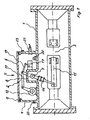
- the encapsulation housing 1 which is filled with SF 6 and accommodates an interrupter unit 2 in its interior, is provided on its periphery with a molded part 4 in the form of a sprue that forms the housing for the switch drive 3, which surrounds the switch drive 3 as a circumferential wall in its full height. So that the switch drive 3 is protected against environmental influences when the switchgear is installed under open-air conditions, the molding 4 forming the housing is closed by the cover 5 by means of the seal 6.
- the housing accommodating the switch drive 3 is thus integrated in the encapsulation housing 1.
- the encapsulation housing 1 is also provided with a projecting outwards, receiving the drive shaft 7 Forming 8, also in the form of a sprue, provided.
- This shape 8 is designed as a closed hood and also within the receiving the switch drive 3 Housing arranged.
- the drive shaft 7 is inside the outwardly projecting, designed as a closed hood Forming 8 pressure-tight by means of a gas seal 9 stored and stands with her protruding outwards Forming 8 protruding end 10 over the coupling linkage 11 and the gear 12 with the motor drive 13 of the Switch drive 3 in connection.
- the drive shaft 7 by means of the drive rod 14 with the axially displaceable contact 15 of the interrupter unit 2 connected.
- Figures 1 and 2 also show that the outwardly projecting, formed as a hood formation 8, which here on the front side by a cover receiving the gas seal 9 is closed, carries the signaling switch 17, the Actuating shaft 18 by means of a linkage 19 with the Coupling linkage 11 and thus with the drive shaft 7 in Connection is established. Since at the same time the heater 20 and the display 21 for the switch position of the interrupter unit 2 within the projection 4 in the form of a sprue are arranged, this means that next to the switch drive 3 also the alarm switch 17, the heater 20 and the display 21 are protected in the formation 4. Eventually the projection 4 also used to make electrical connectors or cable glands 22 for the electrical Concerns within the housing and record it at the same time to be provided with ventilation openings 23.
- the outwardly projecting formed as a hood formation 8, which here on the front side by a cover receiving the gas seal 9 is closed, carries the signaling switch 17, the Actuating shaft 18 by means of a linkage 19 with the Coupling linkage 11 and
- Figure 3 is the encapsulation housing 1 that the Forming 4 in Form of a sprue formed as a circumferential web. about a seal 24 is a switch drive on this web 3 enclosing hood 25 placed.
- the sprue is designed as a closed hood through which Hood 23 added in connection with the peripheral web.
Landscapes
- Engineering & Computer Science (AREA)
- Power Engineering (AREA)
- Gas-Insulated Switchgears (AREA)
- Driving Mechanisms And Operating Circuits Of Arc-Extinguishing High-Tension Switches (AREA)
- Mechanisms For Operating Contacts (AREA)
- Manufacture Of Switches (AREA)
Claims (6)
- Boítier (1) de blindage pour appareil de commutation sous enveloppe métallique et à isolation gazeuse, qui reçoit une unité (2) de coupure, dont le contact (15) mobile peut coulisser axialement sous l'action d'une tringle (14) d'entraínement, qui peut être actionnée au moyen d'un arbre (7) d'entraínement monté dans le boítier (1) de blindage dans un renfoncement (8) en saillie vers l'extérieur par un entraínement (3) de commutateur placé sur le pourtour extérieur du boítier (1) de blindage,
caractérisé en ce que
le boítier (1) de blindage a sur son pourtour, sous la forme d'un culot, une conformation (4) formant un boítier (4) pour l'entraínement du commutateur et le renfoncement (8) est constitué sous la forme d'un culot
et en ce que le renfoncement (8) en saillie vers l'extérieur et recevant au moins l'arbre (7) d'entraínement est placé à l'intérieur du boítier (4) pour l'entraínement du commutateur. - Boítier de blindage suivant la revendication 1,
caractérisé en ce que la conformation (4) entoure, sous la forme d'une paroi faisant le tour, l'entraínement (3) du commutateur sur toute sa hauteur. - Boítier de blindage suivant la revendication 1 et 2,
caractérisé en ce que la conformation (4) est fermée au moyen d'une étanchéité (6) par un couvercle (5). - Boítier de blindage suivant la revendication 1,
caractérisé en ce que la conformation (4) est constituée sous la forme d'une aile qui fait le tour et sur laquelle est posée, par l'intermédiaire d'une étanchéité (23), une hotte (24) entourant l'entraínement (3) du commutateur. - Boítier de blindage suivant la revendication 1 à 4,
caractérisé en ce que l'arbre (7) d'entraínement est monté d'une manière étanche à la pression au moyen d'une étanchéité (9) aux gaz dans la conformation (8) faisant saillie vers l'extérieur et conformée en hotte fermée et est en liaison avec l'entraínement (13) à moteur par son extrémité (10) dépassant de la conformation (8) en saillie vers l'extérieu par l'intermédiaire de la tringlerie (11) d'accouplement. - Boítier de blindage suivant la revendication 1 à 5,
caractérisé en ce que sur la conformation (8) faisant saillie vers l'extérieur et conformée en hotte fermée est placé l'interrupteur (16) de signalisation, dont l'arbre (17) d'actionnement est relié au moyen d'une tringlerie (18) à la tringlerie (11) de couplage et ainsi à l'arbre (7) d'entraínement.
Applications Claiming Priority (2)
| Application Number | Priority Date | Filing Date | Title |
|---|---|---|---|
| DE29620438U | 1996-11-13 | ||
| DE29620438U DE29620438U1 (de) | 1996-11-13 | 1996-11-13 | Kapselungsgehäuse für gasisolierte, metallgekapselte Schaltanlagen |
Publications (3)
| Publication Number | Publication Date |
|---|---|
| EP0843395A2 EP0843395A2 (fr) | 1998-05-20 |
| EP0843395A3 EP0843395A3 (fr) | 1998-10-14 |
| EP0843395B1 true EP0843395B1 (fr) | 2003-10-22 |
Family
ID=8032395
Family Applications (1)
| Application Number | Title | Priority Date | Filing Date |
|---|---|---|---|
| EP97250335A Expired - Lifetime EP0843395B1 (fr) | 1996-11-13 | 1997-11-11 | Boítier pour appareillage de commutation sous enveloppe métallique et à isolation gazeuse |
Country Status (2)
| Country | Link |
|---|---|
| EP (1) | EP0843395B1 (fr) |
| DE (2) | DE29620438U1 (fr) |
Families Citing this family (13)
| Publication number | Priority date | Publication date | Assignee | Title |
|---|---|---|---|---|
| DE29620438U1 (de) * | 1996-11-13 | 1997-01-23 | Siemens AG, 80333 München | Kapselungsgehäuse für gasisolierte, metallgekapselte Schaltanlagen |
| DE19732487C1 (de) * | 1997-07-23 | 1998-11-26 | Siemens Ag | Mehrphasige gasisolierte Schaltanlage mit Trennschaltern für die Hochspannungstechnik |
| DE19815538A1 (de) * | 1998-03-31 | 1999-10-07 | Siemens Ag | Antriebseinrichtungen für Unterbrechereinheiten von Schaltgeräten zur Energieversorgung und -verteilung |
| DE10325682A1 (de) | 2003-06-02 | 2004-12-30 | Siemens Ag | Gasisoliertes Sammelschienenbauteil mit Freiluftdurchführung |
| DE10325684B4 (de) * | 2003-06-02 | 2005-07-28 | Siemens Ag | Schalteranordnung |
| DE10325683B3 (de) | 2003-06-02 | 2004-12-09 | Siemens Ag | Trennschalteranordnung |
| DE10325680A1 (de) * | 2003-06-02 | 2005-01-13 | Siemens Ag | Schaltanlage mit in einer Freiluftdurchführung integrierten Trennschaltern |
| DE102004006062A1 (de) * | 2004-01-30 | 2005-08-18 | Siemens Ag | Druckgasisoliertes Schaltgerät |
| CN100388402C (zh) * | 2005-02-01 | 2008-05-14 | 缪元昌 | 户内交流高压封闭式负荷开关 |
| DE102006038262A1 (de) * | 2006-08-09 | 2008-02-14 | Siemens Ag | Gehäuseanordnung mit einer Grundfläche |
| DE102007003132A1 (de) * | 2007-01-17 | 2008-07-24 | Siemens Ag | Schaltanordnung |
| JP5183831B2 (ja) * | 2010-11-12 | 2013-04-17 | 三菱電機株式会社 | ガス絶縁開閉装置 |
| DE102016203481A1 (de) * | 2016-03-03 | 2017-09-07 | Siemens Aktiengesellschaft | Demontage- oder Montageverfahren für eine druckfluidisolierte Elektroenergieübertragungseinrichtung |
Family Cites Families (16)
| Publication number | Priority date | Publication date | Assignee | Title |
|---|---|---|---|---|
| DE2108266C3 (de) * | 1971-02-17 | 1981-06-19 | Siemens AG, 1000 Berlin und 8000 München | Hochspannungsschalter |
| DE7208413U (de) * | 1972-03-06 | 1979-09-27 | Licentia Patent-Verwaltungs-Gmbh, 6000 Frankfurt | Isolierstützer für druckgasisolierte, metallgekapselte Hochspannungs-Schaltanlagen |
| US3856978A (en) * | 1974-02-21 | 1974-12-24 | Westinghouse Electric Corp | Adherent coating for captivating small particles in gas-insulated electrical equipment |
| NL160439C (nl) * | 1975-04-07 | 1979-10-15 | Coq Bv | Vermogensschakelaar voor hoge spanning met bolvormig metalen vat. |
| DE2927466C2 (de) * | 1979-07-06 | 1983-06-23 | Siemens AG, 1000 Berlin und 8000 München | Elektrisches Mittelspannungs-Schaltfeld |
| CH658946A5 (de) * | 1982-06-07 | 1986-12-15 | Bbc Brown Boveri & Cie | Hochspannungsanlage. |
| JPS61191213A (ja) * | 1985-02-19 | 1986-08-25 | 三菱電機株式会社 | ガス絶縁開閉装置 |
| DE3715053A1 (de) * | 1987-05-06 | 1988-11-17 | Sachsenwerk Ag | Metallgekapselte, mit druckgas gefuellte, mehrphasige hochspannungsschaltanlage |
| JPH0374121A (ja) * | 1989-08-11 | 1991-03-28 | Meidensha Corp | ガス絶縁開閉装置 |
| JPH0479117A (ja) * | 1990-07-19 | 1992-03-12 | Fuji Electric Co Ltd | ガス絶縁開閉装置 |
| DE4306579C2 (de) * | 1993-03-03 | 1996-12-12 | Aeg Energietechnik Gmbh | Gasisolierter Trennschalter |
| DE4320906C2 (de) * | 1993-06-18 | 2000-07-27 | Siemens Ag | Gehäuse für einen druckgasisolierten Hochspannungs- Leistungs-Schalter |
| US5521567A (en) * | 1994-04-08 | 1996-05-28 | S&C Electric Company | Switchgear module and configurations, and method of fabrication and assembly thereof |
| JPH0884411A (ja) * | 1994-09-09 | 1996-03-26 | Toshiba Corp | ガス絶縁開閉装置 |
| DE4446944A1 (de) * | 1994-12-28 | 1996-07-04 | Abb Research Ltd | Hochspannungsanlage |
| DE29620438U1 (de) * | 1996-11-13 | 1997-01-23 | Siemens AG, 80333 München | Kapselungsgehäuse für gasisolierte, metallgekapselte Schaltanlagen |
-
1996
- 1996-11-13 DE DE29620438U patent/DE29620438U1/de not_active Expired - Lifetime
-
1997
- 1997-11-11 DE DE59710885T patent/DE59710885D1/de not_active Expired - Lifetime
- 1997-11-11 EP EP97250335A patent/EP0843395B1/fr not_active Expired - Lifetime
Also Published As
| Publication number | Publication date |
|---|---|
| EP0843395A2 (fr) | 1998-05-20 |
| DE59710885D1 (de) | 2003-11-27 |
| EP0843395A3 (fr) | 1998-10-14 |
| DE29620438U1 (de) | 1997-01-23 |
Similar Documents
| Publication | Publication Date | Title |
|---|---|---|
| EP0843395B1 (fr) | Boítier pour appareillage de commutation sous enveloppe métallique et à isolation gazeuse | |
| EP0005208B1 (fr) | Installation de commutation électrique | |
| EP0678956A1 (fr) | Capteur de courant et tension pour une installation haute tension | |
| EP1249910B1 (fr) | Disjoncteur haute-tension pour une installation de commutation à isolation gaseuse | |
| EP0152611A2 (fr) | Appareillage de commutation blindé métallique à gaz isolant | |
| DE69401800T2 (de) | Mehrzweckstromdurchführung | |
| EP0658964A2 (fr) | Installation de commutation | |
| WO1996027204A1 (fr) | Commande a accumulation d'energie pour un pole d'interrupteur de puissance haute tension rempli de gaz isolant | |
| DE4320906C2 (de) | Gehäuse für einen druckgasisolierten Hochspannungs- Leistungs-Schalter | |
| EP0796502B1 (fr) | Appareillage de commutation mis sous boitier metallique, comportant un interrupteur a vide | |
| DE3936759A1 (de) | Dreipolige, metallgekapselte, druckgasisolierte hochspannungsschaltanlage | |
| EP0593902B2 (fr) | Installation de commutation à moyenne tension | |
| DE102012008130A1 (de) | Antriebseinheit für einen Spindelantrieb | |
| DE4435359C2 (de) | Polsäule eines elektrischen Leistungsschalters | |
| EP1463173A1 (fr) | Appareillage de commutation blindé métallique à isolement gazeux | |
| EP0513945B1 (fr) | Chambre électrique pour un disjoncteur à gaz | |
| EP0171352A1 (fr) | Installation de commutation haute tension blindée à isolation gazeuse | |
| DE3743544A1 (de) | Trennschalter | |
| EP0718942B1 (fr) | Installation à haute tension | |
| DE19958782B4 (de) | Durchführungsstützer und -stromwandler für metallgekapselte, luftisolierte Mittelspannungs-Schaltanlagen | |
| DE102006050477B4 (de) | Mittelspannungsschaltanlage mit Eingießpolteilen und Einfahrkontaktanordnungen | |
| DE19850693B4 (de) | Druckgasisolierte Schaltanlage | |
| DE102006001237A1 (de) | Gasisolierte, dreiphasige gekapselte Schaltanlage | |
| EP0885449B1 (fr) | Interrupteur de puissance avec support de levier de contact isolant | |
| DE2854028A1 (de) | Gehaeuse zur explosionsgeschuetzten aufnahme elektrischer schaltgeraete |
Legal Events
| Date | Code | Title | Description |
|---|---|---|---|
| PUAI | Public reference made under article 153(3) epc to a published international application that has entered the european phase |
Free format text: ORIGINAL CODE: 0009012 |
|
| AK | Designated contracting states |
Kind code of ref document: A2 Designated state(s): CH DE FR LI SE |
|
| PUAL | Search report despatched |
Free format text: ORIGINAL CODE: 0009013 |
|
| AK | Designated contracting states |
Kind code of ref document: A3 Designated state(s): AT BE CH DE DK ES FI FR GB GR IE IT LI LU MC NL PT SE |
|
| 17P | Request for examination filed |
Effective date: 19981117 |
|
| AKX | Designation fees paid |
Free format text: CH DE FR LI SE |
|
| 17Q | First examination report despatched |
Effective date: 20010910 |
|
| GRAH | Despatch of communication of intention to grant a patent |
Free format text: ORIGINAL CODE: EPIDOS IGRA |
|
| GRAS | Grant fee paid |
Free format text: ORIGINAL CODE: EPIDOSNIGR3 |
|
| GRAA | (expected) grant |
Free format text: ORIGINAL CODE: 0009210 |
|
| AK | Designated contracting states |
Kind code of ref document: B1 Designated state(s): CH DE FR LI SE |
|
| REG | Reference to a national code |
Ref country code: CH Ref legal event code: NV Representative=s name: SIEMENS SCHWEIZ AG Ref country code: CH Ref legal event code: EP |
|
| REF | Corresponds to: |
Ref document number: 59710885 Country of ref document: DE Date of ref document: 20031127 Kind code of ref document: P |
|
| PG25 | Lapsed in a contracting state [announced via postgrant information from national office to epo] |
Ref country code: SE Free format text: LAPSE BECAUSE OF FAILURE TO SUBMIT A TRANSLATION OF THE DESCRIPTION OR TO PAY THE FEE WITHIN THE PRESCRIBED TIME-LIMIT Effective date: 20040122 |
|
| ET | Fr: translation filed | ||
| PLBE | No opposition filed within time limit |
Free format text: ORIGINAL CODE: 0009261 |
|
| STAA | Information on the status of an ep patent application or granted ep patent |
Free format text: STATUS: NO OPPOSITION FILED WITHIN TIME LIMIT |
|
| 26N | No opposition filed |
Effective date: 20040723 |
|
| REG | Reference to a national code |
Ref country code: CH Ref legal event code: PCAR Free format text: SIEMENS SCHWEIZ AG;INTELLECTUAL PROPERTY FREILAGERSTRASSE 40;8047 ZUERICH (CH) |
|
| PGFP | Annual fee paid to national office [announced via postgrant information from national office to epo] |
Ref country code: FR Payment date: 20131119 Year of fee payment: 17 |
|
| PGFP | Annual fee paid to national office [announced via postgrant information from national office to epo] |
Ref country code: CH Payment date: 20140206 Year of fee payment: 17 Ref country code: DE Payment date: 20140120 Year of fee payment: 17 |
|
| REG | Reference to a national code |
Ref country code: DE Ref legal event code: R119 Ref document number: 59710885 Country of ref document: DE |
|
| REG | Reference to a national code |
Ref country code: CH Ref legal event code: PL |
|
| PG25 | Lapsed in a contracting state [announced via postgrant information from national office to epo] |
Ref country code: CH Free format text: LAPSE BECAUSE OF NON-PAYMENT OF DUE FEES Effective date: 20141130 Ref country code: LI Free format text: LAPSE BECAUSE OF NON-PAYMENT OF DUE FEES Effective date: 20141130 |
|
| REG | Reference to a national code |
Ref country code: FR Ref legal event code: ST Effective date: 20150731 |
|
| PG25 | Lapsed in a contracting state [announced via postgrant information from national office to epo] |
Ref country code: DE Free format text: LAPSE BECAUSE OF NON-PAYMENT OF DUE FEES Effective date: 20150602 |
|
| PG25 | Lapsed in a contracting state [announced via postgrant information from national office to epo] |
Ref country code: FR Free format text: LAPSE BECAUSE OF NON-PAYMENT OF DUE FEES Effective date: 20141201 |