EP0843410A2 - Elément composite à inductance et capacitance - Google Patents
Elément composite à inductance et capacitance Download PDFInfo
- Publication number
- EP0843410A2 EP0843410A2 EP97119798A EP97119798A EP0843410A2 EP 0843410 A2 EP0843410 A2 EP 0843410A2 EP 97119798 A EP97119798 A EP 97119798A EP 97119798 A EP97119798 A EP 97119798A EP 0843410 A2 EP0843410 A2 EP 0843410A2
- Authority
- EP
- European Patent Office
- Prior art keywords
- glass
- molar
- composite component
- magnetic
- dielectric
- Prior art date
- Legal status (The legal status is an assumption and is not a legal conclusion. Google has not performed a legal analysis and makes no representation as to the accuracy of the status listed.)
- Granted
Links
Images
Classifications
-
- H—ELECTRICITY
- H03—ELECTRONIC CIRCUITRY
- H03H—IMPEDANCE NETWORKS, e.g. RESONANT CIRCUITS; RESONATORS
- H03H7/00—Multiple-port networks comprising only passive electrical elements as network components
- H03H7/01—Frequency selective two-port networks
- H03H7/0115—Frequency selective two-port networks comprising only inductors and capacitors
-
- H—ELECTRICITY
- H03—ELECTRONIC CIRCUITRY
- H03H—IMPEDANCE NETWORKS, e.g. RESONANT CIRCUITS; RESONATORS
- H03H1/00—Constructional details of impedance networks whose electrical mode of operation is not specified or applicable to more than one type of network
- H03H2001/0021—Constructional details
- H03H2001/0057—Constructional details comprising magnetic material
-
- H—ELECTRICITY
- H03—ELECTRONIC CIRCUITRY
- H03H—IMPEDANCE NETWORKS, e.g. RESONANT CIRCUITS; RESONATORS
- H03H1/00—Constructional details of impedance networks whose electrical mode of operation is not specified or applicable to more than one type of network
- H03H2001/0021—Constructional details
- H03H2001/0085—Multilayer, e.g. LTCC, HTCC, green sheets
Definitions
- the present invention relates to a multilayered chip-type inductance-capacitance (LC) composite component, and it particularly relates to an LC composite component obtained by monolithically sintering a capacitor portion and an inductor portion.
- LC inductance-capacitance
- a multilayered chip-type LC composite component obtained by combining an inductor and a capacitor is used in, for example, a passive filter.
- the LC composite component comprises, as the main body of the component, a multilayered structure obtained by layering green sheets of a magnetic material and a dielectric material in turn, and by then monolithically sintering the resulting structure. More specifically, magnetic ceramic portions which provide the inductor and dielectric portions which provide the capacitor are superposed in turn, and the resulting structure is monolithically sintered thereafter.
- dielectric ceramic materials Although there are various types of dielectric ceramic materials, not all can be used directly in the monolithic sintering with a magnetic ceramic material. However, to meet for a wide variety of applications, the use of a still increasing variety of dielectric ceramic materials in LC composite components is strongly requested.
- the effect that is expected by adding a borosilicate glass into the dielectric ceramic material and/or the magnetic ceramic material is controlling the thermal expansion coefficient of the capacitor portion and the inductor portion by complexing the thermal expansion coefficients of the dielectric ceramic material and the magnetic ceramic material.
- the thermal expansion coefficient of a borosilicate glass can be changed by changing the composition and the compositional ratio of the glass.
- the change in composition and compositional ratio influences the physical and chemical properties of the borosilicate glass.
- the glass viscosity whose effective index is the softening point of glass, is greatly affected.
- the change in viscosity also changes the sinterability of the capacitor and the inductor portions. Accordingly, a change in thermal expansion signifies a change in sintering temperature as well, and generates defects such as peeling and warping on the monolithically sintered product component.
- the above disclosures describe nothing on the influence of glass on the joining properties between the dielectric ceramic material and magnetic ceramic material into which the glass is added.
- the composition and the compositional ratio of glass and thereby changing the viscosity of the glass, the interdiffusion rate and the reactivity of the components change between the capacitor portion and the inductor portion to affect the joining properties.
- the borosilicate glass that is contained in the dielectric ceramic layer and the magnetic ceramic layer may undergo degradation in resistances against moisture, acids, and alkalis.
- the incorporation of B 2 O 3 is a cause of bringing about such a degradation on the glass. This effect can be observed particularly in the SiO 2 -poor regions.
- the loss in reliability on the glass by the incorporation of B 2 O 3 may lead to a vital defect for LC composite components by inducing, for instance, interlayer migration in the dielectric ceramic layers of the capacitor portion.
- An object of the present invention is, accordingly, to provide an LC composite component which overcomes the aforementioned problems in the art.
- the present invention relates to an LC composite component comprising a body obtained by monolithically sintering a capacitor portion having a layered structure consisting of a dielectric ceramic layer and an electrode layer with an inductor portion having a layered structure consisting of a magnetic ceramic layer and an electrode layer, which is characterized by the following constitutions that are employed to overcome the aforementioned technological problems.
- the present invention is characterized in that at least one of said dielectric ceramic layer and said magnetic layer contains a glass having a softening point of 800°C or lower, and that said dielectric ceramic layer and said magnetic layer are monolithically sintered at a temperature of 1,000°C or lower.
- the glass is selected as such that it is contained in at least one of said dielectric ceramic layer and said magnetic layer at a concentration of from 0.5 to 90 % by weight.
- borosilicate glass free of B 2 O 3 is used.
- the glass preferably contains, as the principal components thereof, from 1 to 15 % by molar of at least one type of a compound expressed by Ma 2 O (where Ma represents an alkali metal); from 20 to 70 % by molar of at least one type of a compound expressed by MeO (where Me represents an alkaline earth metal); from 5 to 60 % by molar of SiO 2 ; and from 0.5 to 70 % by molar of Bi 2 O 3 .
- the glass preferably contains, as the secondary components thereof, 50 % by molar or less of TiO 2 and 50 % by molar or less of CuO; or 5 % by molar or less of at least one of the group consisting of ZnO, Co 3 O 4 , and NiO; or 5 % by molar or less of at least one of Al 2 O 3 and ZrO 2 ; or 5 % by molar or less of at least one of rare earth oxides; or a combination thereof.
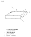
- Fig. 1 is a perspective view showing the external appearance of an LC composite component according to an embodiment of the present invention.
- Fig. 1 In the perspective view of Fig. 1 is shown the external appearance of an LC composite component 1 according to an embodiment of the present invention.
- the LC composite component 1 comprises a main body 4 obtained by monolithically sintering a capacitor portion 2 and an inductor portion 3, and a plurality of external electrodes 5 are formed on the end face of the main body 4 of the component.
- An example of detailed structure of a LC composite component is disclosed in U.S. Patent No. 5,530,411. The disclosure of the U.S. patent is incorporated herein by reference.
- the capacitor portion 2 is made of a layered structure consisting of dielectric ceramic layers and electrode layers
- the inductor portion 3 is made of a layered structure consisting of magnetic ceramic layers and electrode layers.
- the dielectric ceramic layers and/or magnetic layers contain a glass component having a softening point of 800°C or lower, and the capacitor portion 2 is monolithically sintered with the inductor portion 3 at a temperature not higher than 1,000°C.
- the joint between the capacitor portion 2 and the inductor portion 3 is realized by, as is described above, the interdiffusion of a low softening glass contained mainly in the dielectric ceramic layers and/or magnetic layers.
- the use of interdiffusion of low softening glass as a means of forming a joint not only is advantageous in realizing low temperature sintering, but also considerably reduces the stress (residual stress) that forms on the joint interface; that is, because the residual stress in the dielectric ceramic layers and/or magnetic layers containing glass is negligible at temperatures higher than the strain point of glass, the residual stress at lower temperatures can be considerably reduced as compared with the case of a joint formed by solid phase reaction by using a low softening glass in order to adjust the thermal expansion coefficient to be approximately equal.
- the relation between the sintering temperature and the residual stress is mainly determined by the glass viscosity expressed representatively by the softening point of the glass, and the wettability of each of the dielectric and the magnetic materials to the glass.
- a metal having low resistivity and containing, for instance, gold, silver, or copper, as the principal component thereof should be incorporated into the electrode layer of the LC composite component 1.
- the dielectric ceramic layers and the magnetic layers must be sintered at a temperature of 1,000°C or lower.
- the use of a glass having a softening point of 800°C or lower as the additive to the dielectric ceramic layers and/or the magnetic layers enables the sintering at a temperature of 1,000°C or lower.
- the glass above having a softening point of 800°C or lower is preferably added at a concentration of from 0.5 to 90 % by weight.
- a glass containing B 2 O 3 is inferior in resistances against moisture, acids, and alkalis.
- preferably used as the glass is a silicate glass free of B 2 O 3 .
- a glass which readily undergoes crystallization and which has high chemical resistance can be obtained.
- Such a glass increases the reliability of the LC composite component by preventing interlayer migration from occurring in the dielectric layer of the capacitor portion.
- a crystallized glass exhibits an increased strength, and is therefore advantageous concerning resistance against residual stress which generates at temperatures not higher than the strain point.
- the glass preferably contains, as the principal components thereof, from 1 to 15 % by molar of at least one type of a compound expressed by Ma 2 O (where Ma represents an alkali metal); from 20 to 70 % by molar of at least one type of a compound expressed by MeO (where Me represents an alkaline earth metal); from 5 to 60 % by molar of SiO 2 ; and from 0.5 to 70 % by molar of Bi 2 O 3 .
- the component expressed by Ma 2 O functions as to lower the glass viscosity. If the content of Ma 2 O should be lower than 1 % by molar, the glass temperature becomes too high as to make sintering at temperatures not higher than 1,000°C difficult. On the other hand, the content of Ma 2 O exceeding 15 % by molar reversely decreases the moisture resistance and the Q value of the dielectric.
- the component expressed by MeO accelerates the reaction of a dielectric with a glass.
- MeO represents an alkaline earth metal
- the reaction with the dielectric does not proceed, and sintering at temperatures not higher than 1,000°C becomes difficult.
- the presence of MeO elevates the glass temperature and negatively affects the Q value.
- the presence of MeO in excess of 70 % by molar prevents sintering at 1,000°C or lower from being achieved, and considerably impairs the Q value.
- the Bi 2 O 3 component accelerates the reaction between the glass and the dielectric and the magnetic materials, and lowers the glass viscosity. Sintering at 1,000°C becomes difficult if the glass contains less than 0.5 % by molar of Bi 2 O 3 . A glass containing Bi 2 O 3 in excess of 70 % by molar undergoes reaction with the internal electrode layer, and the resistance thereof against moisture is greatly impaired.
- the glass preferably contains, as the secondary components thereof, 50 % by molar or less of TiO 2 and 50 % by molar or less of CuO; or 5 % by molar or less of at least one of the group consisting of ZnO, Co 3 O 4 , and NiO; or 5 % by molar or less of at least one of Al 2 O 3 and ZrO 2 ; or 5 % by molar or less of at least one of rare earth oxides; or a combination thereof.
- TiO 2 accelerates the reaction of a dielectric with a glass, increases the dielectric constant of the dielectric ceramics, and improves the chemical durability.
- TiO 2 present in excess of 50 % by molar elevates the melting temperature of the glass to make sintering difficult to occur at temperatures 1,000°C or lower.
- CuO accelerates the reaction of glass with the dielectric and the magnetic material, and also functions as a crystallizing material of the glass.
- Al 2 O 3 and ZrO 2 ameliorates the chemical durability of the glass and the component body 4.
- Al 2 O 3 and ZrO 2 that are present in excess of 10 % by molar elevates the melting temperature of the glass to make sintering difficult to occur at temperatures 1,000°C or lower.
- ZnO, Co 3 O 4 , and NiO each accelerates the reaction between the glass and the magnetic material as to improve the magnetic properties of the magnetic body.
- ZnO, Co 3 O 4 , or NiO that is present in excess of 5 % by molar makes sintering difficult to occur at temperatures 1,000°C or lower.
- the rare earth oxides accelerate the reaction between the glass and the dielectric or the magnetic materials, and increase the dielectric constant.
- a rare earth oxide present in excess of 5 % by molar impairs the chemical durability.
- Barium titanate (BaTiO 3 ) was used as the dielectric ceramic material, and four types of glass as are shown by DG1, DG2, DG3, and DG4 in Table 1 were prepared to add into the BaTiO 3 based material.
- the glass compositions DG1, DG2, and DG3 are those having a composition falling within the range of the present invention, whereas the glass composition DG4 is a comparative example of a borosilicate glass containing alkaline earth metal oxide at an amount falling outside the range claimed in the present invention.
- Nickel-zinc (Ni-Zn) ferrite material was used as a magnetic ceramic material.
- Four types of glass as are shown by FG1, FG2, FG3, and FG4 in Table 2 were prepared to add into the ferrite material.
- the glass compositions FG1, FG2, and FG3 are those having a composition falling within the range of the present invention, whereas the glass composition FG4 is a comparative example of a borosilicate glass containing alkaline earth metal oxide at an amount falling outside the range claimed in the present invention.
- each of the glass compositions DG1, DG2, DG3, and DG4 was added into the BaTiO 3 dielectric ceramic material at the amount shown in Table 3 below together with a proper quantity of a binder, a plasticizer, and a solvent. The resulting mixtures were each kneaded to prepare the slurries of the dielectric materials. Then, each of the glass compositions FG1, FG2, FG3, and FG4 was added into the Ni-Zn ferrite ceramic material at the amount shown in Table 3 together with a proper quantity of a binder, a plasticizer, and a solvent, and was kneaded to obtain therefrom each of the slurries of the magnetic materials.
- the dielectric slurries and the magnetic slurries thus obtained above were each formed into a sheet 100 ⁇ m or less in thickness by means of doctor blade process.
- the resulting ceramic green sheets were each cut into a sheet 12 mm in length and 12 mm in width.
- an internal electrode pattern was formed on each of the dielectric green sheets to provide a static capacitance, whereas a coil electrode pattern was formed on each of the magnetic green sheets to establish an inductance.
- the dielectric green sheets and the magnetic green sheets were each superposed one after another, and the resulting layered structure was pressed to obtain a final product 3 mm in thickness.
- a component body consisting of a capacitor portion and a inductor portion.
- the thickness of the capacitor portion was the same as that of the inductor portion.
- the resulting layered structure was sintered at a temperature in a range of from 900 to 1,000°C for a duration of 2 hours to obtain the component body.
- An external electrode was then provided to the end plane of the component body.
- the external electrode was provided by applying an electrically conductive paste comprising an Ag powder, glass frit, and an organic vehicle, followed by baking the pattern at 800°C for a duration of 30 minutes.
- LC composite component having an appearance as is shown in Fig. 1.
- the results of the evaluation are shown in Table 3 below.
- samples Nos. 5, 10, 15, and 20 which all contain a comparative glass material FG4 added into a magnetic ceramic material, exhibited inferior sinterability. They were not available as normal sinterings at a temperature of 1,000°C or lower. In case of samples Nos. 16 to 20, into which 18 wt.% of a comparative glass DG4 was added, not only a low sinterability was observed, but also cracks generated at the joint interface between the capacitor portion and the inductor portion.
- the samples Nos. 2 to 4, 7 to 9, and 12 to 14 according to the present invention which comprise one of the glass species DG1, DG2, or DG3 each having a softening point of 800°C or lower being added at an amount of 18 wt.% or less into the dielectric ceramic material, and one of the glass species FG1, FG2, or FG3 each having a softening point of 800°C or lower being added at an amount of 18 wt.% or less into the magnetic ceramic material, exhibited favorable sinterability and mechanical properties.
- the samples Nos. 1, 6, and 11 according to the present invention which comprise one of the glass species DG1, DG2, or DG3 each having a softening point of 800°C or lower being added into the dielectric ceramic material alone, also exhibited favorable sinterability and mechanical properties as in the samples Nos. 2 to 4, 7 to 9, and 12 to 14 above.
- the samples Nos. 1 to 4, 6 to 9, and 11 to 14 By comparing the samples Nos. 1 to 4, 6 to 9, and 11 to 14 with the samples Nos. 5, 10, and 15 to 20, the effect of eliminating B 2 O 3 from the glass added into the dielectric ceramic material and/or the magnetic ceramic material can be observed. More specifically, the samples Nos. 1 to 4, 6 to 9, and 11 to 14 which use a silicate glass free of B 2 O 3 exhibit superior sinterability and mechanical properties as compared with the samples Nos. 5, 10, and 15 to 20 which use a glass containing B 2 O 3 . That is, the glass can be more easily crystallized and achieve a higher strength by eliminating B 2 O 3 from the glass composition. This is advantageous in case residual stress should be considered. Furthermore, because the chemical resistance of the glass can be improved, the interlayer migration in the capacitor portion can be prevented from occurring as to further improve the reliability of the LC composite component.
- the sinterability and the mechanical properties are favorable for the samples Nos. 21 to 24, in which the comparative glass DG4 is added into the dielectric ceramic material at an amount of 50 wt.% together with 10 wt.% of FG1, FG2, or FG3, or 20 wt.% of FG4.
- the insulation resistance thereof was found to decrease from 10 12 to 10 6 ⁇ within 10 hours.
- Example 2 The same procedure as in Example 1 was followed, except for using an Al 2 O 3 material for the dielectric ceramic material.
- the same Ni-Zn ferrite material as that in Example 1 was used for the magnetic ceramic material, while using DG1, DG2, DG3, and DG4 shown in Table 1 as the additive glass materials for the Al 2 O 3 material and the glass materials FG1, FG2, FG3, and FG4 shown in Table 2 for the Ni-Zn ferrite material.
- each of the glass compositions DG1, DG2, DG3, and DG4 was added into the Al 2 O 3 dielectric ceramic material at the amount shown in Table 4 below, together with a proper quantity of a binder, a plasticizer, and a solvent. The resulting mixtures were each kneaded to prepare the slurries of the dielectric materials. Then, each of the glass compositions FG1, FG2, FG3, and FG4 was added into the Ni-Zn ferrite ceramic material at the amount shown in Table 4 together with a proper quantity of a binder, a plasticizer, and a solvent, and was kneaded to obtain therefrom each of the slurries of the magnetic materials. Added Glass Sample No.
- a dielectric green sheet having an internal electrode pattern printed thereon and a magnetic green sheet having a coil electrode pattern printed thereon were each produced by using the thus obtained dielectric slurries and the magnetic slurries and by following a procedure similar to that of Example 1.
- the resulting green sheets were pressed to obtain a layered structure.
- the resulting layered structure was sintered at a temperature of 900°C for a duration of 2 hours to obtain the component body.
- An external electrode was then provided to the end plane of the component body in the same manner as in Example 1 to obtain an LC composite component having an outer appearance shown in Fig. 1.
- resulting LC composite components were each subjected to evaluation tests concerning sinterability and mechanical properties such as joining properties, ⁇ , and the presence of cracks at the joint interface.. The results of the evaluation tests are shown in Table 4.
- the samples Nos. 29, 34, 39, and 44 prepared by adding a comparative glass FG4 exhibited low sinterability, and would not sinter at 900°C, i.e., at a temperature of 1,000°C or lower. The same tendency was observed with increasing addition of glass FG4.
- samples Nos. 40 to 44 in which comparative glass DG4 is added into the dielectric ceramic material, not only low sinterability was observed, but also cracks were found to generate in the joint interface between the capacitor portion and the inductor portion.
- the samples Nos. 26 to 28, 31 to 33, and 36 to 38 according to the present invention which comprise one of the glass species DG1, DG2, or DG3 each having a softening point of 800°C or lower (more specifically, 780°C or lower) being added into the dielectric ceramic material and one of the glass species FG1, FG2, or FG3 each having a softening point of 800°C or lower (more specifically, 780°C or lower) being added into the magnetic ceramic material, exhibited favorable sinterability and mechanical properties.
- the samples Nos. 25, 30, and 35 according to the present invention comprise one of the glass species DG1, DG2, or DG3 each having a softening point of 800°C or lower being added into the dielectric ceramic material alone. These samples also exhibited favorable sinterability and mechanical properties as in the samples Nos. 26 to 28, 31 to 33 and 36 to 38 above.
- Example 2 by comparing the samples Nos. 25 to 28, 30 to 33, and 35 to 38 with the samples Nos. 29, 34, and 39 to 44, it can be seen that the sinterability as well as the mechanical properties ameliorate by eliminating B 2 O 3 from the glass added into the dielectric ceramic material and/or the magnetic ceramic material. More specifically, similar to Example 1, the glass can be more easily crystallized and can achieve a higher strength by eliminating B 2 O 3 from the glass composition. This is advantageous in case residual stress should be considered. Furthermore, because the chemical resistance of the glass can be improved, the interlayer migration in the capacitor portion can be prevented from occurring as to further improve the reliability of the LC composite component.
- an LC composite component comprising a component body consisting of a monolithic sintering of a capacitor portion and an inductor portion
- excellent joining properties between the capacitor portion and an inductor portion is achieved by adding a glass component added into at least one of the dielectric ceramic layer of the capacitor portion and the magnetic ceramic layer of the inductor portion.
- the glass enables sintering of the dielectric ceramics and the magnetic ceramics at a temperature of 1,000°C or lower when a glass having a softening point of 800°C or lower is added into the dielectric body and/or the magnetic body.
- the present invention allows use of a wider variety of dielectric ceramic materials and magnetic ceramic materials in the combination for monolithic sinterings.
- the present invention provides, with further ease, a variety of LC composite components.
Landscapes
- Engineering & Computer Science (AREA)
- Power Engineering (AREA)
- Fixed Capacitors And Capacitor Manufacturing Machines (AREA)
- Coils Or Transformers For Communication (AREA)
Applications Claiming Priority (3)
| Application Number | Priority Date | Filing Date | Title |
|---|---|---|---|
| JP30602896A JP3513787B2 (ja) | 1996-11-18 | 1996-11-18 | Lc複合部品 |
| JP306028/96 | 1996-11-18 | ||
| JP30602896 | 1996-11-18 |
Publications (3)
| Publication Number | Publication Date |
|---|---|
| EP0843410A2 true EP0843410A2 (fr) | 1998-05-20 |
| EP0843410A3 EP0843410A3 (fr) | 2000-05-10 |
| EP0843410B1 EP0843410B1 (fr) | 2008-07-30 |
Family
ID=17952213
Family Applications (1)
| Application Number | Title | Priority Date | Filing Date |
|---|---|---|---|
| EP97119798A Expired - Lifetime EP0843410B1 (fr) | 1996-11-18 | 1997-11-12 | Elément composite à inductance et capacitance |
Country Status (4)
| Country | Link |
|---|---|
| US (1) | US6094111A (fr) |
| EP (1) | EP0843410B1 (fr) |
| JP (1) | JP3513787B2 (fr) |
| DE (1) | DE69738860D1 (fr) |
Cited By (3)
| Publication number | Priority date | Publication date | Assignee | Title |
|---|---|---|---|---|
| EP1978004A1 (fr) * | 2007-03-30 | 2008-10-08 | TDK Corporation | Composition céramique diélectrique, dispositif électronique complexe et condensateur électrique multicouche |
| US7737803B2 (en) | 2005-02-10 | 2010-06-15 | Soshin Electric Co., Ltd. | Electric part including a dielectric portion and a magnetic portion |
| WO2023017199A1 (fr) | 2021-08-10 | 2023-02-16 | Advanced Thermal Devices S.L. | Cathode à base du matériau c12a7:e- "électrure" pour l'émission thermoionique d'électrons et procédé pour son utilisation |
Families Citing this family (10)
| Publication number | Priority date | Publication date | Assignee | Title |
|---|---|---|---|---|
| JP3454164B2 (ja) * | 1998-08-21 | 2003-10-06 | 株式会社村田製作所 | フェライト焼結体 |
| JP2001247365A (ja) * | 2000-03-02 | 2001-09-11 | Murata Mfg Co Ltd | 誘電体セラミック組成物、ならびに、電子部品、電子装置 |
| US6835463B2 (en) * | 2002-04-18 | 2004-12-28 | Oakland University | Magnetoelectric multilayer composites for field conversion |
| JP4619026B2 (ja) * | 2003-10-24 | 2011-01-26 | 京セラ株式会社 | ガラスセラミック基板およびその製造方法 |
| CN102165543A (zh) * | 2008-09-30 | 2011-08-24 | 双信电机株式会社 | 复合电子部件 |
| KR100983125B1 (ko) * | 2008-10-28 | 2010-09-17 | 삼성전기주식회사 | 다층 세라믹 기판의 제조방법 |
| JP5570205B2 (ja) * | 2009-03-26 | 2014-08-13 | 京セラ株式会社 | 磁性焼結体、磁性体と誘電体との複合焼結体、およびそれらの製造方法、ならびにそれらを用いた電子部品 |
| KR101499719B1 (ko) * | 2013-08-09 | 2015-03-06 | 삼성전기주식회사 | 복합 전자부품 및 그 실장 기판 |
| JP6231050B2 (ja) | 2015-07-21 | 2017-11-15 | Tdk株式会社 | 複合電子部品 |
| JP6764658B2 (ja) * | 2016-02-05 | 2020-10-07 | 株式会社村田製作所 | 電子部品 |
Family Cites Families (11)
| Publication number | Priority date | Publication date | Assignee | Title |
|---|---|---|---|---|
| US4011060A (en) * | 1975-10-02 | 1977-03-08 | International Business Machines Corporation | Method of controlling the softening point of solder glass |
| US4746557A (en) * | 1985-12-09 | 1988-05-24 | Murata Manufacturing Co., Ltd. | LC composite component |
| DE3888582T2 (de) * | 1987-07-01 | 1994-10-13 | Tdk Corp | Gesinterter Ferritkörper, Chip-Induktivität und Verbund-LC-Teil. |
| JPH03102705A (ja) * | 1989-09-18 | 1991-04-30 | Murata Mfg Co Ltd | 誘電体磁器組成物 |
| DE3935471A1 (de) * | 1989-10-25 | 1991-05-02 | Hoechst Ag | Keramische stoffzusammensetzung und ihre verwendung |
| EP0506476B1 (fr) * | 1991-03-29 | 1996-06-05 | Ngk Insulators, Ltd. | Filtre diélectrique avec des électrodes de couplage pour relier des résonateurs ou des électrodes, et méthode pour ajuster la caractéristique de fréquence du filtre |
| US5479140A (en) * | 1991-09-27 | 1995-12-26 | Ngk Insulators, Ltd. | Dielectric ceramic composition containing ZnO-B2 O3 -SiO2 glass, method of preparing the same, and resonator and filter using the dielectric ceramic composition |
| US5312674A (en) * | 1992-07-31 | 1994-05-17 | Hughes Aircraft Company | Low-temperature-cofired-ceramic (LTCC) tape structures including cofired ferromagnetic elements, drop-in components and multi-layer transformer |
| JP3227859B2 (ja) * | 1993-01-08 | 2001-11-12 | 株式会社村田製作所 | 非還元性誘電体磁器組成物 |
| JPH07201592A (ja) * | 1993-12-28 | 1995-08-04 | Murata Mfg Co Ltd | 積層型lc複合部品 |
| US5827792A (en) * | 1994-08-30 | 1998-10-27 | Ube Industries, Ltd. | Dielectric ceramic composition |
-
1996
- 1996-11-18 JP JP30602896A patent/JP3513787B2/ja not_active Expired - Lifetime
-
1997
- 1997-11-12 EP EP97119798A patent/EP0843410B1/fr not_active Expired - Lifetime
- 1997-11-12 DE DE69738860T patent/DE69738860D1/de not_active Expired - Lifetime
- 1997-11-17 US US08/971,505 patent/US6094111A/en not_active Expired - Lifetime
Cited By (5)
| Publication number | Priority date | Publication date | Assignee | Title |
|---|---|---|---|---|
| US7737803B2 (en) | 2005-02-10 | 2010-06-15 | Soshin Electric Co., Ltd. | Electric part including a dielectric portion and a magnetic portion |
| US7764143B2 (en) * | 2005-02-10 | 2010-07-27 | Soshin Electric Co., Ltd. | Electronic component including a magnetic layer and a dielectric layer |
| EP1978004A1 (fr) * | 2007-03-30 | 2008-10-08 | TDK Corporation | Composition céramique diélectrique, dispositif électronique complexe et condensateur électrique multicouche |
| US7799718B2 (en) | 2007-03-30 | 2010-09-21 | Tdk Corporation | Dielectric ceramic composition, complex electronic device and multilayer ceramic capacitor |
| WO2023017199A1 (fr) | 2021-08-10 | 2023-02-16 | Advanced Thermal Devices S.L. | Cathode à base du matériau c12a7:e- "électrure" pour l'émission thermoionique d'électrons et procédé pour son utilisation |
Also Published As
| Publication number | Publication date |
|---|---|
| US6094111A (en) | 2000-07-25 |
| JPH10149949A (ja) | 1998-06-02 |
| EP0843410A3 (fr) | 2000-05-10 |
| EP0843410B1 (fr) | 2008-07-30 |
| JP3513787B2 (ja) | 2004-03-31 |
| DE69738860D1 (de) | 2008-09-11 |
Similar Documents
| Publication | Publication Date | Title |
|---|---|---|
| KR100272424B1 (ko) | 적층세라믹커패시터및이것의제조방법 | |
| EP0916630B1 (fr) | Pieces en ceramique non magnetique et en ceramique stratifiee | |
| US6472074B2 (en) | Dielectric ceramic composition | |
| KR100326950B1 (ko) | 유전체 세라믹 조성물 및 적층 세라믹 부품 | |
| KR100379204B1 (ko) | 유전체 세라믹 조성물 및 모놀리식 세라믹 부품 | |
| US6094111A (en) | Inductance-capacitance composite component with a glass having a low temperature softening point | |
| JP5003683B2 (ja) | ガラスセラミック組成物、ガラスセラミック焼結体および積層セラミック電子部品 | |
| CA1331279C (fr) | Ceramique de titanate de magnesium et substrat dielectrique double utilisant celle-ci | |
| JPWO2008018408A1 (ja) | ガラスセラミック組成物、ガラスセラミック焼結体および積層セラミック電子部品 | |
| KR19980070404A (ko) | 모놀리식 세라믹 커패시터 | |
| US6487065B1 (en) | Multilayer ceramic capacitor and manufacturing method thereof | |
| JP2666388B2 (ja) | 積層セラミックコンデンサ | |
| JPH1025157A (ja) | 誘電体セラミック組成物および積層セラミックコンデンサ | |
| KR960006230B1 (ko) | 고주파 유전체 재료와 공진기 및 그 제조방법 | |
| JP3471839B2 (ja) | 誘電体磁器組成物 | |
| US6623845B1 (en) | Glass-ceramic composition, and electronic component and multilayer LC composite component using the same | |
| US7265071B2 (en) | Dielectric ceramic composition and multilayer ceramic part using the same | |
| JP3084992B2 (ja) | セラミック基板 | |
| JPH11243006A (ja) | 磁性体磁器組成物およびそれを用いたインダクタ部品 | |
| EP1130003A1 (fr) | Composition verre-ceramique, composants electroniques et multicomposant lc multicouche utilisant ladite composition | |
| KR100425993B1 (ko) | 적층 전자 부품 | |
| JP3645046B2 (ja) | 非磁性セラミックおよびセラミック積層部品 | |
| EP1315231A2 (fr) | Composition céramique diélectrique et des pièces céramiques laminées utilisant celle-ci | |
| JP3804135B2 (ja) | 積層セラミックコンデンサ | |
| JPH02251122A (ja) | 磁器コンデンサの電極用導電性ペースト |
Legal Events
| Date | Code | Title | Description |
|---|---|---|---|
| PUAI | Public reference made under article 153(3) epc to a published international application that has entered the european phase |
Free format text: ORIGINAL CODE: 0009012 |
|
| 17P | Request for examination filed |
Effective date: 19971112 |
|
| AK | Designated contracting states |
Kind code of ref document: A2 Designated state(s): DE FR GB |
|
| AX | Request for extension of the european patent |
Free format text: AL;LT;LV;MK;RO;SI |
|
| PUAL | Search report despatched |
Free format text: ORIGINAL CODE: 0009013 |
|
| AK | Designated contracting states |
Kind code of ref document: A3 Designated state(s): AT BE CH DE DK ES FI FR GB GR IE IT LI LU MC NL PT SE |
|
| AX | Request for extension of the european patent |
Free format text: AL;LT;LV;MK;RO;SI |
|
| RIC1 | Information provided on ipc code assigned before grant |
Free format text: 7H 03H 7/01 A, 7H 03H 1/00 B |
|
| AKX | Designation fees paid |
Free format text: DE FR GB |
|
| 17Q | First examination report despatched |
Effective date: 20070227 |
|
| RAP1 | Party data changed (applicant data changed or rights of an application transferred) |
Owner name: MURATA MANUFACTURING CO., LTD. |
|
| GRAP | Despatch of communication of intention to grant a patent |
Free format text: ORIGINAL CODE: EPIDOSNIGR1 |
|
| GRAS | Grant fee paid |
Free format text: ORIGINAL CODE: EPIDOSNIGR3 |
|
| GRAA | (expected) grant |
Free format text: ORIGINAL CODE: 0009210 |
|
| AK | Designated contracting states |
Kind code of ref document: B1 Designated state(s): DE FR GB |
|
| REG | Reference to a national code |
Ref country code: GB Ref legal event code: FG4D |
|
| REF | Corresponds to: |
Ref document number: 69738860 Country of ref document: DE Date of ref document: 20080911 Kind code of ref document: P |
|
| PLBE | No opposition filed within time limit |
Free format text: ORIGINAL CODE: 0009261 |
|
| STAA | Information on the status of an ep patent application or granted ep patent |
Free format text: STATUS: NO OPPOSITION FILED WITHIN TIME LIMIT |
|
| 26N | No opposition filed |
Effective date: 20090506 |
|
| REG | Reference to a national code |
Ref country code: FR Ref legal event code: PLFP Year of fee payment: 19 |
|
| REG | Reference to a national code |
Ref country code: FR Ref legal event code: PLFP Year of fee payment: 20 |
|
| PGFP | Annual fee paid to national office [announced via postgrant information from national office to epo] |
Ref country code: DE Payment date: 20161121 Year of fee payment: 20 Ref country code: GB Payment date: 20161122 Year of fee payment: 20 Ref country code: FR Payment date: 20161118 Year of fee payment: 20 |
|
| REG | Reference to a national code |
Ref country code: DE Ref legal event code: R071 Ref document number: 69738860 Country of ref document: DE |
|
| REG | Reference to a national code |
Ref country code: GB Ref legal event code: PE20 Expiry date: 20171111 |
|
| PG25 | Lapsed in a contracting state [announced via postgrant information from national office to epo] |
Ref country code: GB Free format text: LAPSE BECAUSE OF EXPIRATION OF PROTECTION Effective date: 20171111 |