EP0843419A2 - Steuereinrichting für elektronische Geräte - Google Patents
Steuereinrichting für elektronische Geräte Download PDFInfo
- Publication number
- EP0843419A2 EP0843419A2 EP97308084A EP97308084A EP0843419A2 EP 0843419 A2 EP0843419 A2 EP 0843419A2 EP 97308084 A EP97308084 A EP 97308084A EP 97308084 A EP97308084 A EP 97308084A EP 0843419 A2 EP0843419 A2 EP 0843419A2
- Authority
- EP
- European Patent Office
- Prior art keywords
- electronic equipment
- data
- signal
- amplifier
- changer
- Prior art date
- Legal status (The legal status is an assumption and is not a legal conclusion. Google has not performed a legal analysis and makes no representation as to the accuracy of the status listed.)
- Withdrawn
Links
Images


Classifications
-
- H—ELECTRICITY
- H04—ELECTRIC COMMUNICATION TECHNIQUE
- H04L—TRANSMISSION OF DIGITAL INFORMATION, e.g. TELEGRAPHIC COMMUNICATION
- H04L12/00—Data switching networks
- H04L12/28—Data switching networks characterised by path configuration, e.g. LAN [Local Area Networks] or WAN [Wide Area Networks]
- H04L12/2803—Home automation networks
- H04L12/2816—Controlling appliance services of a home automation network by calling their functionalities
-
- G—PHYSICS
- G11—INFORMATION STORAGE
- G11B—INFORMATION STORAGE BASED ON RELATIVE MOVEMENT BETWEEN RECORD CARRIER AND TRANSDUCER
- G11B27/00—Editing; Indexing; Addressing; Timing or synchronising; Monitoring; Measuring tape travel
- G11B27/002—Programmed access in sequence to a plurality of record carriers or indexed parts, e.g. tracks, thereof, e.g. for editing
-
- G—PHYSICS
- G06—COMPUTING OR CALCULATING; COUNTING
- G06Q—INFORMATION AND COMMUNICATION TECHNOLOGY [ICT] SPECIALLY ADAPTED FOR ADMINISTRATIVE, COMMERCIAL, FINANCIAL, MANAGERIAL OR SUPERVISORY PURPOSES; SYSTEMS OR METHODS SPECIALLY ADAPTED FOR ADMINISTRATIVE, COMMERCIAL, FINANCIAL, MANAGERIAL OR SUPERVISORY PURPOSES, NOT OTHERWISE PROVIDED FOR
- G06Q10/00—Administration; Management
- G06Q10/10—Office automation; Time management
-
- G—PHYSICS
- G11—INFORMATION STORAGE
- G11B—INFORMATION STORAGE BASED ON RELATIVE MOVEMENT BETWEEN RECORD CARRIER AND TRANSDUCER
- G11B27/00—Editing; Indexing; Addressing; Timing or synchronising; Monitoring; Measuring tape travel
- G11B27/10—Indexing; Addressing; Timing or synchronising; Measuring tape travel
- G11B27/34—Indicating arrangements
-
- H—ELECTRICITY
- H04—ELECTRIC COMMUNICATION TECHNIQUE
- H04B—TRANSMISSION
- H04B1/00—Details of transmission systems, not covered by a single one of groups H04B3/00 - H04B13/00; Details of transmission systems not characterised by the medium used for transmission
- H04B1/06—Receivers
- H04B1/16—Circuits
- H04B1/20—Circuits for coupling gramophone pick-up, recorder output, or microphone to receiver
- H04B1/205—Circuits for coupling gramophone pick-up, recorder output, or microphone to receiver with control bus for exchanging commands between units
-
- H—ELECTRICITY
- H04—ELECTRIC COMMUNICATION TECHNIQUE
- H04N—PICTORIAL COMMUNICATION, e.g. TELEVISION
- H04N5/00—Details of television systems
- H04N5/76—Television signal recording
- H04N5/765—Interface circuits between an apparatus for recording and another apparatus
-
- G—PHYSICS
- G06—COMPUTING OR CALCULATING; COUNTING
- G06F—ELECTRIC DIGITAL DATA PROCESSING
- G06F15/00—Digital computers in general; Data processing equipment in general
- G06F15/16—Combinations of two or more digital computers each having at least an arithmetic unit, a program unit and a register, e.g. for a simultaneous processing of several programs
- G06F15/163—Interprocessor communication
- G06F15/173—Interprocessor communication using an interconnection network, e.g. matrix, shuffle, pyramid, star, snowflake
-
- G—PHYSICS
- G11—INFORMATION STORAGE
- G11B—INFORMATION STORAGE BASED ON RELATIVE MOVEMENT BETWEEN RECORD CARRIER AND TRANSDUCER
- G11B2220/00—Record carriers by type
- G11B2220/20—Disc-shaped record carriers
- G11B2220/25—Disc-shaped record carriers characterised in that the disc is based on a specific recording technology
- G11B2220/2537—Optical discs
- G11B2220/2545—CDs
-
- H—ELECTRICITY
- H04—ELECTRIC COMMUNICATION TECHNIQUE
- H04N—PICTORIAL COMMUNICATION, e.g. TELEVISION
- H04N5/00—Details of television systems
- H04N5/44—Receiver circuitry for the reception of television signals according to analogue transmission standards
- H04N5/445—Receiver circuitry for the reception of television signals according to analogue transmission standards for displaying additional information
Definitions
- the invention relates to a control system for electronic equipment in which electronic equipment comprising, for example, a plurality of A/V (Audio/Visual) equipment connected are concentratedly controlled by one controller.
- A/V Audio/Visual
- the conventional A/V equipment it is possible to connect a plurality of equipment having the GUI function, to select a video output and an audio output of each equipment, and to supply them to, for example, a monitor.
- a remote controller to control each of those equipment is an exclusive-use controller for each equipment. Therefore, the user needs to exchange and grasp the different remote controller every equipment to be operated and to operate it. There is, consequently, a problem such that the GUI function provided to inherently improve an operability causes a deterioration in operability due to the operation such that the user exchanges and grasps the different remote controller.
- an A/V equipment such that a number of A/V equipment connected are controlled in a lump, for example, what is called an A/V amplifier also existed.
- information of the other A/V equipment connected is previously stored in a memory provided in the amplifier and a function is selected for the amplifier by a remote controller or the like using infrared rays is selected, thereby controlling those equipment connected.
- an A/V equipment having a control corresponding to the A/V amplifier for example, what is called a CD (Compact Disc) changer in which a number of CDs are enclosed and a specific CD is selected from a number of CDs and is reproduced is connected to the A/V amplifier.
- a CD Compact Disc
- the CD changer when the CD changer is selected as a function, a control corresponding to the CD changer is displayed on a monitor connected to the amplifier. The user operates the remote controller or the like on the basis of the display, so that he can control the CD changer connected.
- a list of titles of the CDs enclosed in the CD changer can be displayed on the monitor by a predetermined operation.
- the titles which are displayed in this instance are stored into the memory of the A/V amplifier by transmitting information represented by characters reproduced, for example, in the CD changer to the A/V amplifier or transmitting information represented by characters by a direct input to the A/V amplifier by a remocon or the like by the user.
- the A/V amplifier since the equipment which is connected cannot be specified, a large capacity in the memory cannot be allocated to the specific equipment. Therefore, there is a problem such that the A/V amplifier itself cannot display not so large amount of information.
- the changer having the GUI function exists.
- many information such as names of artists, titles of pieces of music recorded in the CDs, and the like can be displayed to the monitor.
- the user selects the CD by the remote controller and can select a desired piece of music with respect to the selected CD and can reproduce it.
- Various information represented by characters has previously been stored in the memory provided for the CD changer.
- the CD changer different from the foregoing A/V amplifier, since information such as functions of the set, the number of discs, and the like is obvious, an optimum memory construction can be used. In this case, however, the user has to operate the remote controllers of both of the A/V amplifier and the CD changer.
- an object of the invention to provide a concentrated control system of electronic equipment which can perform a concentrated remote control in a system to which A/V equipment having the GUI function is connected.
- a concentrated control system of electronic equipment for concentratedly controlling a plurality of electronic equipment characterized by comprising: at least one or more electronic equipment which are connected by a predetermined method and can be controlled by a predetermined control signal; a controller for transferring the control signal to at least one of the electronic equipment; transfer means for transferring a data signal to each of the electronic equipment; discriminating means for discriminating contents of the data signal transferred by the transfer means; and selecting means for selecting the electronic equipment on the basis of a discrimination result in the discriminating means and displaying display data from the selected electronic equipment, wherein a control is shifted to the selected electronic equipment.
- a controller which is used in a system for concentratedly controlling a plurality of electronic equipment which comprises at least one or more electronic equipment which are connected by a predetermined method and can be controlled by a predetermined control signal, transfer means for transferring a data signal to each of the electronic equipment, discriminating means for discriminating contents of the data signal transferred by the transfer means, and selecting means for selecting the electronic equipment on the basis of a discrimination result in the discriminating means and displaying display data from the selected electronic equipment, and in which a control is shifted to the selected electronic equipment on the basis of the control signal, characterized in that the control signal is transferred to at least one of the electronic equipment for the system.
- electronic equipment which can be controlled by a predetermined control signal and in which a plurality of electronic equipment can be connected, characterized by comprising: transfer means for transferring a data signal to the other electronic equipment connected; receiving means for receiving a data signal from the other electronic equipment connected; discriminating means for discriminating contents of the data signal received by the receiving means; and selecting means for selecting the other electronic equipment on the basis of a discrimination result in the discriminating means and displaying display data from the selected other electronic equipment, wherein a control is shifted to the other electronic equipment on the basis of a predetermined control signal.
- the control is shifted to the electronic equipment selected on the basis of an instruction of the controller and the display data from the selected electronic equipment is displayed, so that the electronic equipment can be concentratedly controlled.
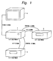
- FIG. 1 shows an example of an A/V system to which the invention is applied.
- a control of the A/V equipment according to the invention will be schematically explained.
- a path of video signal and audio signal hereinafter, referred to as an A/V signal line
- a path of a control signal for controlling each of connected A/V equipment hereinafter, referred to as a control signal line
- An instruction code comprising various information and a control signal is included in the control signal, thereby enabling an interlocking operation to be performed among the connected A/V equipment.
- an amplifier 1, a CD player 2, and a cassette deck 3 are connected by control signal lines and A/V signal lines, respectively.
- a video output of the amplifier 1 and a monitor 4 for displaying a video signal to a display are connected by a connecting line.
- a play button of the CD player 2 when a play button of the CD player 2 is depressed and the CD player is set into a play mode, a signal indicative of the play mode is outputted so as to transfer as a control signal to the control signal line.
- a function button as a switch to select a function of the amplifier 1 is automatically switched so as to select the A/V signal input path from the CD player 2 on the basis of the control signal.
- the user can listen to an audio signal reproduced by the CD player 2.
- an image signal indicative of, for instance, a setting mode of the CD player 2 is outputted from the CD player 2
- the image signal is supplied to the monitor 4 through the amplifier 1 and an image is displayed to the monitor 4 on the basis of the image signal.
- a signal indicating that the cassette deck 3 is in the play mode is outputted as a control signal from the cassette deck 3.
- the A/V signal input path is automatically switched from the path from the CD player 2 to the path from the cassette deck 3.
- the user can listen to an audio signal reproduced by the cassette deck 3.
- the image signal is supplied to the monitor 4 through the amplifier 1 and an image based on the image signal is displayed on the monitor 4.
- the equipment which was set into the play mode notifies the other equipment of the setting mode, thereby allowing various switches corresponding to the notified equipment to be automatically switched. Since such a notification is not a command which is sent to the connected equipment from the side where information composed of the control signal is transmitted, in the equipment which received the information, the received information is selected or omitted and the optimum state is derived.
- a control opposite to the above control is also possible. That is, in the amplifier 1, an instruction code to the other A/V equipment connected is transmitted as a control signal, thereby enabling the other A/V equipment connected to be controlled.
- the function button of the amplifier 1 is set so as to select, for instance, the A/V signal input path from the CD player 2.
- a control signal so as to set the CD player 2 into the play mode is automatically outputted from the amplifier 1.
- a CD is automatically played by the CD player 2 which received the control signal. Since the control signal is also supplied to the cassette deck 3 together with the CD player 2, if the cassette deck 3 is in the play mode in this instance, a control so as to stop it can be also performed.
- a plurality of A/V equipment can be simultaneously controlled by one operation.
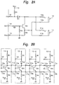
- Fig. 2A shows an example of a circuit construction of a control signal input/output section which enables the control signal to a plurality of equipment to be transmitted as mentioned above.
- An input signal from an output port (not shown) of a microcomputer of the A/V equipment is supplied to a terminal 14.
- the terminal 14 is connected to a base of a transistor TR1 through a resistor R2.
- a resistor R3 is connected between the base of the transistor TR1 and a grounding terminal 15.
- An emitter of the transistor TR1 is connected to the grounding terminal 15 through a resistor R4 and is also connected to contact terminals 10b and llb of terminals 10 and 11, respectively.
- An input is supplied to an input port (not shown) of the microcomputer through a terminal 12.
- a resistor R1 is connected between the terminal 12 and a power source terminal 13.
- the terminal 12 is connected to an anode of a diode D1.
- a cathode of the diode D1 is connected to a collector of the transistor TR1 and is also connected to the contact terminals 10a and lla of the terminals 10 and 11, respectively.
- the control signal input section is provided for each A/V equipment and the terminals 10 and 11 of each A/V equipment are mutually connected.
- a plurality of such circuits are connected by the terminals 10 and 11, they can be considered as an OR circuit in which the transistor TR1 of each circuit is used as a switch.
- a signal at the "L" level is supplied as an initial state to the terminal 14 of each circuit.
- a signal at the "H” level is outputted to the terminal 11 of each circuit.
- the level at the terminal 11 of each circuit can be set to the "L" level.
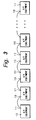
- a plurality of A/V equipment can be serially connected. That is, as shown in Fig. 3, by mutually connecting the terminal 10 or 11 provided for each equipment to the terminal 10 or 11 of the other equipment, a construction shown in Fig. 2B mentioned above is realized.
- the control signal can be transmitted from any one of the connected equipment and any equipment can receive the transmitted signal. According to this construction, the number of equipment which are connected by a serial chain is not limited.
- the number of equipment which can be connected is limited by a factor such as a capacity of a transmission line which is used for connection or the like.
- Fig. 4 shows an example of a transferring method of a data signal among the A/V equipment according to the embodiment.
- the signal at the "L" level is outputted as data for the signal at the "H" level which is set to be default.
- the data is classified depending on a length of interval of the "L" level.
- a start bit indicates the start of data transmission.
- Bit data is expressed by an on bit. The on bit of a long interval indicates "1" and the on bit of a short interval indicates "0". The bit data is separated by an off bit at the "H” level. An example of a length of interval of each bit is shown below.
- a length of interval corresponding to each data can be also set to another length. It is preferable to set the length in correspondence to a communicating speed.
- the data is constructed by setting eight bits, namely, one byte to a minimum unit and is transferred.
- Fig. 5 shows an example of a data construction.
- First one byte indicates a control code.
- the control code shows a name of connected A/V equipment and also indicates a distinction about whether the data is instruction data to the equipment or mode data from the equipment. For instance, in the foregoing example of Fig. 1, when the data signal to be transferred is an instruction to the CD player 2, the control code is set to "90". When it is the data that is transmitted from the CD player 2 and indicates the mode of the CD player 2, the control code is set to "98".
- a data size of the above data is not particularly limited, actually, it is preferable to set it to about 16 bytes in consideration of a point such as a transfer speed or the like.
- the off bit and the on bit are transmitted at the same timing from different equipment, there is a possibility such that a conflict of the signals occurs and erroneous data is transmitted or received.
- the off bit at the "H" level is used as an on bit at the "L” level.
- the signal supplied from the terminal 14 is inverted at the terminal 12 and is detected. By using such a nature and by monitoring the own data signal in each equipment, the conflict can be detected.
- the conflict is detected, for example, the data signal is again transmitted after a predetermined time interval is delayed.
- Fig. 6 shows an example of a construction of an A/V system according to the embodiment and this is an example in which an A/V amplifier 20 and a CD changer 30 are connected through the terminal 10 or 11.
- a monitor 40 to display a video image is connected to the A/V amplifier 20.
- a plurality of (for example, 200) CDs can be enclosed in the CD changer 30.
- two going and returning systems are shown as signal paths between terminals 10 or 11 in the diagram. To avoid complexity, portions such as an audio signal system and the like which are not directly concerned with the present invention are omitted.
- a microcomputer 21 is made up of, for instance, a microprocessor and a necessary memory such as RAM or ROM.
- the microcomputer 21 has a display unit 25 for converting character data or predetermined control data into an image signal that can be displayed by the monitor 40. Further, although not shown, the foregoing control signal input/output section shown in Fig. 2A exists between the microcomputer 21 and the terminals 10 and 11. The control signal supplied from the terminal 10 or 11 is supplied to the microcomputer 21 through the control signal input/output section.
- a cursor signal is formed in the microcomputer 21.
- the cursor signal assists the user when he designates coordinates on a screen of the monitor 40. For example, a shape of hand or an arrow which is pointed out is displayed on the monitor 40.
- the cursor signal is supplied to one input terminal of an image synthesizing circuit 22.
- image data based on data stored in a memory 23 is formed.
- the image data is converted into an image signal by the display unit 25.
- the image signal is supplied to one input terminal of a switching circuit 24 whose selection is controlled by a control signal that is outputted from the microcomputer 21.
- An output of the switching circuit 24 is supplied to the other input terminal of the image synthesizing circuit 22.
- the image signals supplied to one and the other input terminals are synthesized by the image synthesizing circuit 22.
- the synthetic image signal is supplied to the monitor 40 and is displayed.
- the image synthesis which is performed in the image synthesizing circuit 22 is executed so that two picture planes will not influence each display using an existing technique.
- the cursor can freely move in the picture plane.
- the A/V amplifier 20 can be remote controlled. Although not shown, such a remote control is realized by a method whereby, for example, the amplifier 20 has a photosensing unit of an infrared signal and an infrared signal is transmitted to the photosensing unit by a remote control commander (hereinafter, abbreviated to a "remocon") which can modulate a control command for the amplifier 20 and can transmit a modulated signal as an infrared signal.
- a remote control commander hereinafter, abbreviated to a "remocon”
- the infrared signal is received by the A/V amplifier 20, the signal is analyzed by the microcomputer 21 of the A/V amplifier 20.
- the amplifier 20 is controlled on the basis of an analysis result.
- a direction sensing device by, for example, a gyro mechanism or the like is built in the remocon. Movement data is formed on the basis of direction data detected by the direction sensing device. In this case, when a valid range of the screen of the monitor 40 exists in the direction where the remocon directs, actual coordinates of the screen of the monitor 40 are set to coordinate information. The movement data is formed on the basis of the coordinate information. The cursor is moved on the screen of the monitor 40 on the basis of the movement data. When a predetermined operation is performed for the remocon by the user, the function shown at the position on the screen of the monitor 40 where the cursor exists is designated and the designated function is realized.
- the signal which is transmitted from the remocon is not limited to the foregoing infrared signal.
- a frequency modulated radio wave can be used as such a signal.
- the signal can be detected in a range wider than that in case of using the infrared signal.
- the formation of the movement data based on the instruction of the remocon is not limited to the foregoing method using the direction sensing device built in the remocon.
- the formation of the movement data can be also performed on the basis of the operation of what is called a 4-directions-key, joystick, or the like.
- the foregoing control signal input/output section shown in Fig. 2A exists between a microcomputer 31 comprising a microprocessor, an RAM, an ROM, and the like and terminals 10' and 11'.
- the control signal supplied from the terminal 10 or 11 is supplied to the microcomputer 31 through the control signal input/output section.
- the microcomputer 31 has a display unit 33 for converting character data or predetermined control data into an image signal which can be displayed by the monitor 40.
- Image data based on the data stored in a memory 32 is formed in the microcomputer 31.
- the image data is converted into an image signal by the display unit 33 and is supplied as a video output to the A/V amplifier 20.
- the image signal is supplied to the other input terminal of the switching circuit 24.
- a mechanical unit 34 to actually exchange or drive the CD is controlled by a control signal from the microcomputer 31.
- a power supply of the CD changer 30 is turned on preliminarily or simultaneously with a power supply of the A/V amplifier 20 is turned on.
- the above power-on operation is realized, for example, by providing power supplying means which is interlocked with the A/V amplifier 20 for the A/V amplifier 20 and by supplying a power source of the CD changer 30 from the power supplying means.
- a data signal including information (model data) indicative of each equipment is transmitted from the terminal 10 or 11 of each equipment.
- the model data signal of each of the connected equipment is received by the A/V amplifier 20, the equipment connected to the amplifier 20 is discriminated.
- the model data signal indicative of the CD changer 30 is generated from the CD changer 30.
- the model data signal is received by the A/V amplifier 30, a fact that the CD changer 30 is connected to the A/V amplifier 20 is discriminated.
- information indicating that, for instance, the CD changer 30 has the video output is allowed to be included in the model data signal, thereby enabling the A/V amplifier 20 to recognize such a fact.
- Fig. 7 shows an example of the first display picture plane on the monitor 40.
- the switching circuit 24 of the A/V amplifier 20 shown in Fig. 6 one input terminal as a microcomputer 21 side is selected.
- the display picture plane is formed by the microcomputer 21 on the basis of the information stored in the memory 23.
- the image supplied to the image synthesizing circuit 22 through the switching circuit 24 and the cursor formed by the microcomputer 21 are synthesized in the image synthesizing circuit 22.
- the synthetic image signal is supplied to the monitor 40, so that an image is displayed.
- various control displays are arranged on a picture plane 50.
- a display arranged at the right edge of the picture plane 50 is a sound volume control display.
- a control display is arranged to two stages at the lower edge of the picture plane 50.
- the display at the lower edge is a control display that is peculiar to the equipment selected by the function in the A/V amplifier 20.
- a control display regarding the selection of the CD is performed at the upper stage, and a control display regarding the reproduction of the selected CD is performed at the lower stage, respectively.
- a control display to display a menu for switching the function of the amplifier 20 is arranged at the upper edge of the picture plane 50 and a control display to display a menu for audio control is arranged at the left edge, respectively.
- An image which is supplied from the equipment designated by the function can be displayed in the center portion of the picture plane 50. The display in the center portion will be described hereinlater.
- a cursor 51 is displayed at an arbitrary position on the picture plane.
- the cursor 51 is moved on the basis of the movement data which is obtained by the foregoing method and is overlaid to a desired control display of the picture plane 50.
- a predetermined operation for the remocon for example, by depressing an "ENTER" key provided for the remocon, a control shown in the control display on which the cursor 51 is overlaid is selected.
- the operating mode is switched and the display of the picture plane 50 is set to contents shown in Fig. 8 or 9.
- the displays of Figs. 8 and 9 are based on the image signal which is supplied from the CD changer 30. That is, when "LIST" is selected, the control signal including a mode switching code is transmitted from the A/V amplifier 20 to the CD changer 30 by the control of the microcomputer 21. In the CD changer 30, an image signal is formed by the microcomputer 31 on the basis of the mode switching code and is outputted.
- an input terminal of the switching circuit 24 is switched from one input terminal to the other input terminal as a CD changer 30 side by the control of the microcomputer 21.
- the image signal outputted from the microcomputer 31 is supplied to the image synthesizing circuit 22 through the switching circuit 24.
- the image signal and the cursor signal supplied from the microcomputer 21 are synthesized and displayed on the monitor 40.
- a list of the titles of the CDs enclosed in the CD changer 30 is displayed (picture plane 52).
- a list of music pieces recorded in the selected CD is displayed (picture plane 54).
- the operating mode is further switched and the display of the picture plane 52 is shifted to a display of a picture plane 54 of Fig. 9.
- the control signal which is supplied from the A/V amplifier 20 to the CD changer 30 is made up of coordinate data of the cursor 51 at a position where the "ENTER" key was depressed.
- the coordinate data is supplied as a control signal to the microcomputer 31 of the CD changer 30 from the microcomputer 21 through the terminal 10 or 11 and terminal 10' or 11'.
- the picture plane control is shifted from the A/V amplifier 20 to the CD changer 30. That is, in the microcomputer 31, the image data (image data to display the foregoing picture plane 52 or 54) supplied to the A/V amplifier 20 and the supplied coordinate data are made correspond and the control based on the control display displayed on the picture plane 52 or 54 is performed.
- the cursor 51 is matched with the control display displayed on the picture plane 52 and, for instance, the "ENTER" button is depressed.
- An infrared signal including data indicative of the position of the cursor is transmitted from the remocon to the infrared photosensing unit of the A/V amplifier 20.
- This signal is analyzed by the microcomputer 21.
- a cursor image signal is formed in the microcomputer 21.
- the cursor image signal and the image signal supplied from the CD changer 30 are synthesized by the image synthesizing circuit 22 and the picture plane 52 is formed and displayed on the monitor 40.
- the coordinate data of the cursor 51 is also supplied to the microcomputer 31 of the CD changer 30.
- the contents of the control are discriminated on the basis of the supplied coordinate data and the image data for the picture plane 52.
- the image data is formed on the basis of the contents of the control. For example, the title data of the CDs which has previously been stored in the memory 32 is read out and the image data is formed by the microcomputer 31 on the basis of the title data which was read out.
- the image data is converted into an image signal by the display unit 33 and is supplied as video output to the A/V amplifier 20.
- the control of the CD changer 30 by the remocon of the A/V amplifier 20 is performed.
- a list of the titles of the CDs enclosed in the CD changer 30 is displayed on the picture plane 52 shown in Fig. 8.
- the user can select a desired CD from the displayed title list by the operation of the remocon.
- a desired CD for example, although 200 CDs can be enclosed in the CD changer 30, for instance, ten titles can be displayed in a lump on the picture plane 52.
- the other titles can be sequentially displayed by operating a scroll bar 53 provided at the right edge of the picture plane 52 by using the remocon.
- the above display can be performed by a method whereby the title data of the CDs is sequentially read out from the memory 32 in the CD changer 30 in association with the operation of the scroll bar 53 by the remocon.
- the selection of the CD based on the picture plane 52 is also similarly performed.
- a CD title display line where the cursor exists is emphasized by an inversion display or the like.
- the CD is selected.
- the music title data of the CDs enclosed in the CD changer 30 can be preliminarily stored in the memory 32.
- image data for displaying the picture plane 54 is produced in the microcomputer 31 and is converted into the image signal by the display unit 33.
- the image signal is supplied as a video output to the A/V amplifier 20.
- An "EXIT” button 55 is provided for the picture planes 52 and 54 which are displayed on the basis of the video output supplied from the CD changer 30. By designating the button 55, the screen can be returned to the previous picture plane. For example, when the "EXIT" button 55 is designated on the picture plane 54, the picture plane 52 is displayed. When the button 55 is designated on the picture plane 52, the control is shifted from the CD changer 30 to the A/V amplifier 20. Such a shift is performed by generating a predetermined control signal from the microcomputer 31 to the microcomputer 21. On the basis of the control signal, the switching circuit 24 is switched and the picture plane 50 formed by the microcomputer 31 is displayed on the monitor 40.
- two kinds of instruction codes to instruct different controls exist in the control signal which is generated from the A/V amplifier 20 to the CD changer 30.
- the instruction codes for example, the first code is set to "903A” and the second code is set to "9039".
- the first code is used in, for example, a case where the cursor can be freely moved on each picture plane as mentioned above.
- the cursor since the cursor can freely move in the picture plane, for example, only when the "ENTER" key is depressed in the remocon, the coordinate data of the cursor at that time is transmitted from the A/V amplifier 20 to the CD changer 30.
- a predetermined control is performed to the CD changer 30 in response to the coordinate data.
- the cursor display is formed on the A/V amplifier 20 side.
- the second code is used in the case where, for example, the cursor is moved in each picture plane every control display.
- This state corresponds to a case where the remocon of the A/V amplifier 20 has the upper, lower, left, and right direction keys or a cross-key as mentioned above.
- an instruction code so as to perform the cursor movement corresponding to the depressed key is transmitted as cursor movement data from the A/V amplifier 20 to the CD changer 30.
- the display of the cursor movement due to the movement data is executed on the CD changer 30 side.
- first and second instruction codes for example, by selecting the "EXIT" button 55 in the picture plane 52, the operating mode is switched and the picture plane control can be returned from the CD changer 30 to the A/V amplifier 20.
- the instruction code is transmitted from the CD changer 30 to the A/V amplifier 20.
- the switching circuit 24 is switched in accordance with the instruction code.
- the CD changer 30 can output the video image
- the invention is not limited to such an example. That is, the invention can be also applied to a case where the other A/V equipment which is connected to the A/V amplifier 20 doesn't have the video output.
- information of the equipment to be connected is previously recorded and when, for example, the forgoing "LIST" key is selected, the information of the corresponding equipment is read out from the memory 23.
- An image signal is formed on the basis of the read-out information and is displayed on the monitor 40.
- the above display is performed to the center portion of the picture plane 50 shown in Fig. 7 mentioned above.
- the user can select the CD title by, for example, the remocon operation on the basis of the display of the picture plane 50.
- the control signal of the connected A/V equipment can be transferred to each equipment and, in association with the selection of the equipment, the control is shifted to the relevant equipment, there is an effect such that the user can perform the operation of each A/V equipment without changing and grasping the different remocon.
- the equipment can be controlled on the control picture plane which the connected equipment has, there are effects such that the maximum information of the equipment can be obtained and the operability is improved.
Landscapes
- Engineering & Computer Science (AREA)
- Signal Processing (AREA)
- Computer Networks & Wireless Communication (AREA)
- Business, Economics & Management (AREA)
- Strategic Management (AREA)
- Multimedia (AREA)
- Entrepreneurship & Innovation (AREA)
- Human Resources & Organizations (AREA)
- Marketing (AREA)
- General Business, Economics & Management (AREA)
- Data Mining & Analysis (AREA)
- Operations Research (AREA)
- Quality & Reliability (AREA)
- Tourism & Hospitality (AREA)
- Physics & Mathematics (AREA)
- Economics (AREA)
- General Physics & Mathematics (AREA)
- Theoretical Computer Science (AREA)
- Automation & Control Theory (AREA)
- Selective Calling Equipment (AREA)
- Details Of Television Systems (AREA)
- Controls And Circuits For Display Device (AREA)
Applications Claiming Priority (3)
| Application Number | Priority Date | Filing Date | Title |
|---|---|---|---|
| JP8291109A JPH10116058A (ja) | 1996-10-14 | 1996-10-14 | 電子機器の集中制御システム |
| JP291109/96 | 1996-10-14 | ||
| JP29110996 | 1996-10-14 |
Publications (2)
| Publication Number | Publication Date |
|---|---|
| EP0843419A2 true EP0843419A2 (de) | 1998-05-20 |
| EP0843419A3 EP0843419A3 (de) | 2000-05-03 |
Family
ID=17764577
Family Applications (1)
| Application Number | Title | Priority Date | Filing Date |
|---|---|---|---|
| EP97308084A Withdrawn EP0843419A3 (de) | 1996-10-14 | 1997-10-13 | Steuereinrichting für elektronische Geräte |
Country Status (7)
| Country | Link |
|---|---|
| US (1) | US6313812B1 (de) |
| EP (1) | EP0843419A3 (de) |
| JP (1) | JPH10116058A (de) |
| KR (1) | KR100481415B1 (de) |
| CN (1) | CN1110929C (de) |
| MY (1) | MY118254A (de) |
| TW (1) | TW371332B (de) |
Cited By (2)
| Publication number | Priority date | Publication date | Assignee | Title |
|---|---|---|---|---|
| EP1116630A3 (de) * | 1999-12-24 | 2003-11-26 | Siemens Aktiengesellschaft | Audio- und/oder Videosystem, insbesondere für Kraftfahrzeuge oder Heimanwendungen |
| US8401682B2 (en) | 2000-10-12 | 2013-03-19 | Bose Corporation | Interactive sound reproducing |
Families Citing this family (9)
| Publication number | Priority date | Publication date | Assignee | Title |
|---|---|---|---|---|
| US6622158B1 (en) * | 1998-04-20 | 2003-09-16 | Sony Corporation | Character information copying system, recording apparatus, and recording method |
| US6571139B1 (en) * | 1998-05-29 | 2003-05-27 | Sony Corporation | Information processing apparatus, information processing system, information processing method, and providing medium |
| JP2001282426A (ja) * | 2000-03-30 | 2001-10-12 | Canon Inc | データ通信システム、装置、方法及び記憶媒体 |
| US7286745B1 (en) * | 2000-05-03 | 2007-10-23 | Sony Corporation | Providing a capability to sort contents data and to maintain a current sorting mode |
| FR2854254B1 (fr) * | 2003-04-22 | 2005-06-17 | Schneider Electric Ind Sas | Terminal d'exploitation, notamment pour automatismes |
| WO2005015943A1 (en) * | 2003-08-07 | 2005-02-17 | Samsung Electronics Co., Ltd. | A/v system available for integrated control and method of controlling the same |
| JP4198069B2 (ja) | 2004-01-07 | 2008-12-17 | シャープ株式会社 | 電子機器 |
| CN101137948B (zh) * | 2005-03-08 | 2013-07-03 | 皇家飞利浦电子股份有限公司 | 修改程序行为的系统、方法和定制内容的设备 |
| JP4179367B2 (ja) | 2006-09-05 | 2008-11-12 | ソニー株式会社 | 情報処理システム、情報処理装置、情報処理方法、プログラムおよび記録媒体 |
Family Cites Families (10)
| Publication number | Priority date | Publication date | Assignee | Title |
|---|---|---|---|---|
| WO1991007739A1 (en) * | 1989-11-14 | 1991-05-30 | Imtech International, Inc. | Moving message display method and apparatus |
| JP3007407B2 (ja) | 1990-10-25 | 2000-02-07 | パイオニア株式会社 | データ通信システム |
| US5488357A (en) | 1993-01-06 | 1996-01-30 | Sony Corporation | Remote controlling method and system feature starting method and controlling method for audio/visual system |
| JP3201051B2 (ja) * | 1993-02-05 | 2001-08-20 | ソニー株式会社 | リモートコントロールシステム |
| US5475835A (en) * | 1993-03-02 | 1995-12-12 | Research Design & Marketing Inc. | Audio-visual inventory and play-back control system |
| US5621456A (en) * | 1993-06-22 | 1997-04-15 | Apple Computer, Inc. | Methods and apparatus for audio-visual interface for the display of multiple program categories |
| US5510828A (en) * | 1994-03-01 | 1996-04-23 | Lutterbach; R. Steven | Interactive video display system |
| US5598523A (en) * | 1994-03-31 | 1997-01-28 | Panasonic Technologies, Inc. | Method and system for displayed menu activation using a matching distinctive arrangement of keypad actuators |
| US5850218A (en) * | 1997-02-19 | 1998-12-15 | Time Warner Entertainment Company L.P. | Inter-active program guide with default selection control |
| US6111614A (en) * | 1997-10-17 | 2000-08-29 | Sony Corporation | Method and apparatus for displaying an electronic menu having components with differing levels of transparency |
-
1996
- 1996-10-14 JP JP8291109A patent/JPH10116058A/ja active Pending
-
1997
- 1997-10-07 TW TW086114701A patent/TW371332B/zh not_active IP Right Cessation
- 1997-10-07 US US08/944,961 patent/US6313812B1/en not_active Expired - Fee Related
- 1997-10-11 KR KR1019970052196A patent/KR100481415B1/ko not_active Expired - Fee Related
- 1997-10-13 MY MYPI97004801A patent/MY118254A/en unknown
- 1997-10-13 EP EP97308084A patent/EP0843419A3/de not_active Withdrawn
- 1997-10-13 CN CN97125981A patent/CN1110929C/zh not_active Expired - Fee Related
Cited By (6)
| Publication number | Priority date | Publication date | Assignee | Title |
|---|---|---|---|---|
| EP1116630A3 (de) * | 1999-12-24 | 2003-11-26 | Siemens Aktiengesellschaft | Audio- und/oder Videosystem, insbesondere für Kraftfahrzeuge oder Heimanwendungen |
| US8401682B2 (en) | 2000-10-12 | 2013-03-19 | Bose Corporation | Interactive sound reproducing |
| US8977375B2 (en) | 2000-10-12 | 2015-03-10 | Bose Corporation | Interactive sound reproducing |
| US9223538B2 (en) | 2000-10-12 | 2015-12-29 | Bose Corporation | Interactive sound reproducing |
| US10140084B2 (en) | 2000-10-12 | 2018-11-27 | Bose Corporation | Interactive sound reproducing |
| US10481855B2 (en) | 2000-10-12 | 2019-11-19 | Bose Corporation | Interactive sound reproducing |
Also Published As
| Publication number | Publication date |
|---|---|
| KR19980032751A (ko) | 1998-07-25 |
| MY118254A (en) | 2004-09-30 |
| KR100481415B1 (ko) | 2005-08-24 |
| CN1202654A (zh) | 1998-12-23 |
| EP0843419A3 (de) | 2000-05-03 |
| TW371332B (en) | 1999-10-01 |
| US6313812B1 (en) | 2001-11-06 |
| JPH10116058A (ja) | 1998-05-06 |
| CN1110929C (zh) | 2003-06-04 |
Similar Documents
| Publication | Publication Date | Title |
|---|---|---|
| CA2176983C (en) | Remote control for home audio system | |
| EP1833050B1 (de) | Navigationssystem für elektronische Konsumgüter und Verfahren dazu | |
| US20020040474A1 (en) | Video processing device | |
| US5050003A (en) | Image processing apparatus capable of displaying a plurality of screens | |
| JPH0785597B2 (ja) | 遠隔制御装置 | |
| US6313812B1 (en) | Single remote control system for plurality of audio and visual equipment | |
| EP0515104B1 (de) | Fernbedienungsvorrichtung | |
| JP2002345050A (ja) | リモートコントロール装置 | |
| JPH11213174A (ja) | 動画像編集方法 | |
| JPH0478078B2 (de) | ||
| EP0687377A1 (de) | Kombination von Aufzeichnungsvorrichtung und Quellenauswahlvorrichtung | |
| JP2687392B2 (ja) | リモートコントロール装置 | |
| JP2001204089A (ja) | リモコン装置 | |
| JP2730091B2 (ja) | 遠隔操作指令システム | |
| JP3158012B2 (ja) | 学習リモコンシステム及びリモコン信号学習装置 | |
| US5216227A (en) | Index displaying device for a video disk player | |
| KR100406992B1 (ko) | 하나의 오에스디 화면을 통해 각 장치의 제어가 가능한콤비네이션 시스템 | |
| JP3606378B2 (ja) | ビデオ無線送受信システム | |
| EP1061658B1 (de) | Audiosystem mit grafischen Benutzerschnittstelle | |
| JP3387157B2 (ja) | 複合機器操作システム | |
| JP2002182834A (ja) | 仮想ボタン式電子機器及びそれを用いた電子機器システム、並びに仮想ボタンによるモード制御方法 | |
| JPH02180497A (ja) | リモートコントロール装置 | |
| JP3541598B2 (ja) | リモコン装置 | |
| JP2000187549A (ja) | ワイヤレスキ―ボ―ド | |
| JP2718219B2 (ja) | 信号選択装置 |
Legal Events
| Date | Code | Title | Description |
|---|---|---|---|
| PUAI | Public reference made under article 153(3) epc to a published international application that has entered the european phase |
Free format text: ORIGINAL CODE: 0009012 |
|
| AK | Designated contracting states |
Kind code of ref document: A2 Designated state(s): DE FR GB |
|
| AX | Request for extension of the european patent |
Free format text: AL;LT;LV;RO;SI |
|
| PUAL | Search report despatched |
Free format text: ORIGINAL CODE: 0009013 |
|
| AK | Designated contracting states |
Kind code of ref document: A3 Designated state(s): AT BE CH DE DK ES FI FR GB GR IE IT LI LU MC NL PT SE |
|
| AX | Request for extension of the european patent |
Free format text: AL;LT;LV;RO;SI |
|
| 17P | Request for examination filed |
Effective date: 20001017 |
|
| AKX | Designation fees paid |
Free format text: DE FR GB |
|
| STAA | Information on the status of an ep patent application or granted ep patent |
Free format text: STATUS: THE APPLICATION HAS BEEN WITHDRAWN |
|
| 18W | Application withdrawn |
Withdrawal date: 20020930 |