EP0844045A1 - Spanneinrichtung für Plattentrennmaschine - Google Patents
Spanneinrichtung für Plattentrennmaschine Download PDFInfo
- Publication number
- EP0844045A1 EP0844045A1 EP97120299A EP97120299A EP0844045A1 EP 0844045 A1 EP0844045 A1 EP 0844045A1 EP 97120299 A EP97120299 A EP 97120299A EP 97120299 A EP97120299 A EP 97120299A EP 0844045 A1 EP0844045 A1 EP 0844045A1
- Authority
- EP
- European Patent Office
- Prior art keywords
- panels
- tubular body
- locating
- elements
- clamping device
- Prior art date
- Legal status (The legal status is an assumption and is not a legal conclusion. Google has not performed a legal analysis and makes no representation as to the accuracy of the status listed.)
- Granted
Links
Images


Classifications
-
- B—PERFORMING OPERATIONS; TRANSPORTING
- B23—MACHINE TOOLS; METAL-WORKING NOT OTHERWISE PROVIDED FOR
- B23Q—DETAILS, COMPONENTS, OR ACCESSORIES FOR MACHINE TOOLS, e.g. ARRANGEMENTS FOR COPYING OR CONTROLLING; MACHINE TOOLS IN GENERAL CHARACTERISED BY THE CONSTRUCTION OF PARTICULAR DETAILS OR COMPONENTS; COMBINATIONS OR ASSOCIATIONS OF METAL-WORKING MACHINES, NOT DIRECTED TO A PARTICULAR RESULT
- B23Q3/00—Devices holding, supporting, or positioning work or tools, of a kind normally removable from the machine
- B23Q3/18—Devices holding, supporting, or positioning work or tools, of a kind normally removable from the machine for positioning only
-
- B—PERFORMING OPERATIONS; TRANSPORTING
- B23—MACHINE TOOLS; METAL-WORKING NOT OTHERWISE PROVIDED FOR
- B23Q—DETAILS, COMPONENTS, OR ACCESSORIES FOR MACHINE TOOLS, e.g. ARRANGEMENTS FOR COPYING OR CONTROLLING; MACHINE TOOLS IN GENERAL CHARACTERISED BY THE CONSTRUCTION OF PARTICULAR DETAILS OR COMPONENTS; COMBINATIONS OR ASSOCIATIONS OF METAL-WORKING MACHINES, NOT DIRECTED TO A PARTICULAR RESULT
- B23Q7/00—Arrangements for handling work specially combined with or arranged in, or specially adapted for use in connection with, machine tools, e.g. for conveying, loading, positioning, discharging, sorting
- B23Q7/04—Arrangements for handling work specially combined with or arranged in, or specially adapted for use in connection with, machine tools, e.g. for conveying, loading, positioning, discharging, sorting by means of grippers
- B23Q7/043—Construction of the grippers
Definitions
- the present invention relates to a clamping device for panel cutting machines, in particular for cutting multilayer panels, and which may be used to advantage on horizontal cutting machines with an upper pressure clamping bar.
- Clamping devices for panel cutting machines are known to comprise at least one gripper, which in turn normally comprises a substantially rectangular-section box frame, a gripper assembly for gripping the panels and which is fitted to and projects from one end of the box frame, and (for cutting multilayer panels) two comb-shaped locating elements screwed to said end of the box frame, on either side of the gripper assembly.
- said multilayer panels are each defined by a flat supporting body, normally of wood, and by two sheets of cover material glued to the top and bottom surfaces of the supporting body.
- the multilayer panels are stacked and positioned against the comb-shaped locating elements, so that the supporting body of each multilayer panel rests against a respective tooth, and the sheets of cover material project in relation to the respective supporting body and engage respective gaps between adjacent teeth.
- the clamping device may be called upon to handle stacks of multilayer panels of different sizes, in particular different thicknesses, which means replacing the locating elements on the device with others designed to handle panels of a different size.
- a clamping device for a machine for cutting panels, in particular multilayer panels, and comprising a frame in turn having a tubular body; gripping means for gripping the panels; and at least one substantially comb-shaped locating element against which the multilayer panels are positioned; the clamping device being characterized in that said at least one substantially comb-shaped locating element releasably engages, by means of at least one appendix, at least a respective groove integral with the tubular body.
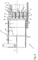
- Number 1 in Figures 1 and 2 indicates a clamping device fittable preferably, but not necessarily, to a cutting machine (in particular of the type featuring an upper pressure clamping bar) for cutting panels 2.
- each panel comprises a flat supporting body 3 made preferably, but not necessarily, of wood; and two sheets 4 of cover material glued to the top and bottom surfaces of supporting body 3.
- Device 1 comprises a frame 5 having, in the example shown, a substantially rectangular-section tubular body 6 extending coaxially with an axis 7; a known gripper assembly 8 fitted to frame 5 and for gripping multilayer panels 2; and two locating elements 9 against which multilayer panels 2 are positioned before being gripped by gripper assembly 8.
- device 1 may also comprises a respective supporting element 10 integral with tubular body 6 and directly supporting locating element 9.
- Supporting elements 10 are not essential for correct operation of the system, in that each locating element 9 may be fitted directly to tubular body 6.
- gripper assembly 8 comprises two jaws 11 and 12; jaw 11 is defined by a plate 13 parallel to axis 7, and which is fitted externally and in projecting manner to one end of tubular body 6; and jaw 12 is defined by an arm 14 housed inside tubular body 6 and having a first end portion hinged to and inside tubular body 6, and a second end portion opposite the first and facing plate 13 outside tubular body 6.
- the second end portion of arm 14 is flat, is substantially parallel to plate 13, and is fitted underneath with a pad of plastic material for more effectively clamping multilayer panels 2.
- Gripper assembly 8 also comprises a known hydraulic actuator (not shown) fitted to frame 5 and for so moving arm 14 as to move the second end portion of arm 14 towards or away from plate 13.
- the two supporting elements 10 are fitted integrally to tubular body 6, directly on plate 13 and on either side of the second end portion of arm 14, and each comprise a respective preferably, but not necessarily, T-shaped groove 15 extending perpendicularly to plate 13 along a lateral surface 16 of supporting element 10.
- the lateral surfaces 16 of the two supporting elements 10 lie in the same plane, which is perpendicular to both axis 7 and plate 13.
- Each locating element 9 is substantially comb-shaped, and comprises a number of aligned teeth 17 against which a stack 18 of multilayer panels 2 is positioned. More specifically, each panel 2 in stack 18 is so positioned that respective supporting body 3 rests against a respective tooth 17, and the two respective sheets 4 of cover material project with respect to supporting body 3 and engage respective gaps between the tooth 17 against which supporting body 3 rests and the two adjacent teeth 17.
- Each locating element 9 also comprises, on the opposite side to teeth 17, an appendix 19 complementary in shape to groove 15, and extending perpendicularly to plate 13 along substantially the whole length of locating element 9.
- Appendix 19 releasably engages respective groove 15 so that respective locating element 9, once fitted to respective supporting element 10, is substantially perpendicular to plate 13.
- the two grooves 15 in respective surfaces 16 may extend parallel to plate 13, so that the two appendixes 19 of respective locating elements 9 also extend parallel to plate 13 to maintain locating elements 9 substantially perpendicular to plate 13.
- grooves 15 are "dove-tailed.”
- supporting elements 10 are dispensed with altogether, and the two locating elements 9 are connected directly to tubular body 6 by providing tubular body 6 with grooves 15 mating with respective appendixes 19 on locating elements 9.
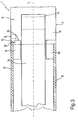
- Figure 3 shows a particular embodiment of the present invention wherein, as opposed to comprising a pair of substantially comb-shaped locating elements 9 as in the Figure 1 and 2 embodiment, clamping device 1 comprises only one locating element 9, and the second supporting element 10 has a completely smooth lateral surface 16, i.e. with no groove 15.
- the Figure 4 apparatus 20 for handling a number of panels 2 comprises a pair of clamping devices 1, 1', the outermost portion of each of which comprises a substantially comb-shaped locating element 9.
- the lateral surfaces 16 of supporting elements 10 may be used for locating nonmultilayer panels 2.
- supporting elements 10 to be used for locating both multilayer panels 2 when fitted with respective locating elements 9, and nonmultilayer panels 2 with no sheets of cover material glued to the top and bottom surfaces of the main central body, it is important that the lateral surfaces 16 of respective supporting elements 10 face jaws 11, 12 and in the opposite direction to the feed direction of panels 2 (multilayer or nonmultilayer). More specifically, supporting elements 10, and possibly also respective locating elements 9, may be confined within the overall dimensions of tubular body 6, as opposed to projecting laterally with respect to tubular body 6.
- the main advantage of device 1 as described above is that of enabling fast, straightforward, low-cost replacement of locating elements 9 without excessively complicating the structure of device 1.
Landscapes
- Engineering & Computer Science (AREA)
- Mechanical Engineering (AREA)
- Jigs For Machine Tools (AREA)
- Treatment Of Fiber Materials (AREA)
- Devices For Post-Treatments, Processing, Supply, Discharge, And Other Processes (AREA)
- Sawing (AREA)
Applications Claiming Priority (2)
| Application Number | Priority Date | Filing Date | Title |
|---|---|---|---|
| ITBO960596 | 1996-11-20 | ||
| IT96BO000596A IT1286779B1 (it) | 1996-11-20 | 1996-11-20 | Dispositivo di presa per macchina sezionatrice di pannelli |
Publications (2)
| Publication Number | Publication Date |
|---|---|
| EP0844045A1 true EP0844045A1 (de) | 1998-05-27 |
| EP0844045B1 EP0844045B1 (de) | 2002-02-20 |
Family
ID=11341729
Family Applications (1)
| Application Number | Title | Priority Date | Filing Date |
|---|---|---|---|
| EP97120299A Expired - Lifetime EP0844045B1 (de) | 1996-11-20 | 1997-11-19 | Spanneinrichtung für Plattentrennmaschine |
Country Status (6)
| Country | Link |
|---|---|
| US (1) | US5957444A (de) |
| EP (1) | EP0844045B1 (de) |
| AT (1) | ATE213444T1 (de) |
| DE (1) | DE69710560T2 (de) |
| ES (1) | ES2172733T3 (de) |
| IT (1) | IT1286779B1 (de) |
Families Citing this family (3)
| Publication number | Priority date | Publication date | Assignee | Title |
|---|---|---|---|---|
| US6238323B1 (en) * | 1999-09-14 | 2001-05-29 | The Simonson Family Limited Partnership Rlllp | Cable crossover exercise apparatus |
| US20140048996A1 (en) * | 2012-08-16 | 2014-02-20 | Roddy M. Bullock | Stabilizing Device |
| CN113391473A (zh) * | 2021-06-28 | 2021-09-14 | 深圳市华星光电半导体显示技术有限公司 | 基板切割机夹板及基板切割方法 |
Citations (2)
| Publication number | Priority date | Publication date | Assignee | Title |
|---|---|---|---|---|
| US4767985A (en) * | 1985-09-24 | 1988-08-30 | The United States Of America As Represented By The Secretary Of The Air Force | Claw grip contact probe for flat packs |
| DE9101640U1 (de) * | 1991-02-13 | 1991-05-02 | Hwang, King-Kuo, Kao-Hsiung City | Hydraulischer Maschinenarm für CNC-Drehmaschinen |
Family Cites Families (4)
| Publication number | Priority date | Publication date | Assignee | Title |
|---|---|---|---|---|
| US2567586A (en) * | 1950-08-24 | 1951-09-11 | Raymond E Werder | Template for setting timbers for uniform nailing |
| US5148605A (en) * | 1991-08-27 | 1992-09-22 | Julia Juan L | Forming leveling tool |
| US5407182A (en) * | 1993-10-25 | 1995-04-18 | Hartley; Thomas | Spacing jig |
| JPH0883739A (ja) * | 1994-09-13 | 1996-03-26 | Rohm Co Ltd | 側面電極付き電子部品の製造方法並びに製造用の治具 |
-
1996
- 1996-11-20 IT IT96BO000596A patent/IT1286779B1/it active IP Right Grant
-
1997
- 1997-11-19 AT AT97120299T patent/ATE213444T1/de not_active IP Right Cessation
- 1997-11-19 US US08/997,191 patent/US5957444A/en not_active Expired - Fee Related
- 1997-11-19 DE DE69710560T patent/DE69710560T2/de not_active Expired - Lifetime
- 1997-11-19 ES ES97120299T patent/ES2172733T3/es not_active Expired - Lifetime
- 1997-11-19 EP EP97120299A patent/EP0844045B1/de not_active Expired - Lifetime
Patent Citations (2)
| Publication number | Priority date | Publication date | Assignee | Title |
|---|---|---|---|---|
| US4767985A (en) * | 1985-09-24 | 1988-08-30 | The United States Of America As Represented By The Secretary Of The Air Force | Claw grip contact probe for flat packs |
| DE9101640U1 (de) * | 1991-02-13 | 1991-05-02 | Hwang, King-Kuo, Kao-Hsiung City | Hydraulischer Maschinenarm für CNC-Drehmaschinen |
Also Published As
| Publication number | Publication date |
|---|---|
| US5957444A (en) | 1999-09-28 |
| ITBO960596A0 (it) | 1996-11-20 |
| IT1286779B1 (it) | 1998-07-17 |
| ES2172733T3 (es) | 2002-10-01 |
| DE69710560D1 (de) | 2002-03-28 |
| ITBO960596A1 (it) | 1998-05-20 |
| EP0844045B1 (de) | 2002-02-20 |
| DE69710560T2 (de) | 2002-10-17 |
| ATE213444T1 (de) | 2002-03-15 |
Similar Documents
| Publication | Publication Date | Title |
|---|---|---|
| JP2003192132A (ja) | 裁断片堆積体をパレットから荷下ろしするための方法およびこの方法を実施するための装置および持上げ手段 | |
| CN107444727B (zh) | 导光板自动组装设备 | |
| EP0686464B1 (de) | Ausbrechvorrichtung in einer Schneidevorrichtung | |
| US6513303B2 (en) | Method and unit for banding groups of bank notes | |
| CN107848131B (zh) | 用于执行印刷产品的敞开的开本缘边的切割作业的机构 | |
| EP1477404A2 (de) | Vorrichtung zum Verpacken eines Produkts | |
| CN109746972B (zh) | 用于执行印刷产品的敞开的规格边缘的切割操作的机构 | |
| US5957444A (en) | Clamping device for panel cutting machines | |
| FR2960181A1 (fr) | Procede de mise en volume d'une decoupe de carton et installation pour sa mise en oeuvre | |
| EP1477447A1 (de) | Falzwalze und Faltverfahren für papierverarbeitende Maschinen | |
| AU687169B2 (en) | A gripper bar and a device for fastening to a set of chains in a machine for processing flat workpieces | |
| JPS6366044A (ja) | 積載束から用紙ブロックを個別化するための方法及び装置 | |
| CN104661919B (zh) | 瓷砖包装机内的纸板夹紧处理装置 | |
| JP2008200804A (ja) | 断裁装置 | |
| US5312222A (en) | Process and device for aligning stacks of cutouts in a packaging machine | |
| JP6790106B2 (ja) | インサートシートを把持するためのデバイス、装填デバイス、ブランクを受け入れるためのステーション、及びシートの形態の要素を加工するための機械 | |
| CN116648337B (zh) | 工具夹持组件和组件 | |
| EP1129967A3 (de) | Greifersystem zur automatischen Entnahme von Stangen flacher Güter aus einer Transportverpackung | |
| ITFI20000041A1 (it) | Dispositivo di piegatura per materiale in foglio, macchina per la produzione di manufatti in foglio e metodo di piegatura impiegante detto d | |
| JP2001315711A (ja) | ストラッピングマシン用グリッパ | |
| EP1002729A1 (de) | Verfahren und Vorrichtung zum Schneiden von Umreifungsbändern für Stapel von Etiketten oder Zuschnitten | |
| CN116552943B (zh) | 一种纸垛上料机器人 | |
| US20030071410A1 (en) | Module for temporarily storing flat printed products and printed product further processing device | |
| GB2090815A (en) | Removing batches of sheets from a stack | |
| AU2022232991B2 (en) | Positioning assembly and sheet material processing machine |
Legal Events
| Date | Code | Title | Description |
|---|---|---|---|
| PUAI | Public reference made under article 153(3) epc to a published international application that has entered the european phase |
Free format text: ORIGINAL CODE: 0009012 |
|
| AK | Designated contracting states |
Kind code of ref document: A1 Designated state(s): AT BE DE ES IT |
|
| AX | Request for extension of the european patent |
Free format text: AL;LT;LV;MK;RO;SI |
|
| 17P | Request for examination filed |
Effective date: 19981123 |
|
| AKX | Designation fees paid |
Free format text: AT BE DE ES |
|
| RBV | Designated contracting states (corrected) |
Designated state(s): AT BE DE ES |
|
| GRAG | Despatch of communication of intention to grant |
Free format text: ORIGINAL CODE: EPIDOS AGRA |
|
| 17Q | First examination report despatched |
Effective date: 20010328 |
|
| GRAG | Despatch of communication of intention to grant |
Free format text: ORIGINAL CODE: EPIDOS AGRA |
|
| GRAH | Despatch of communication of intention to grant a patent |
Free format text: ORIGINAL CODE: EPIDOS IGRA |
|
| RAP1 | Party data changed (applicant data changed or rights of an application transferred) |
Owner name: BIESSE S.P.A. |
|
| GRAH | Despatch of communication of intention to grant a patent |
Free format text: ORIGINAL CODE: EPIDOS IGRA |
|
| GRAA | (expected) grant |
Free format text: ORIGINAL CODE: 0009210 |
|
| RBV | Designated contracting states (corrected) |
Designated state(s): AT BE DE ES IT |
|
| AK | Designated contracting states |
Kind code of ref document: B1 Designated state(s): AT BE DE ES IT |
|
| PG25 | Lapsed in a contracting state [announced via postgrant information from national office to epo] |
Ref country code: BE Free format text: LAPSE BECAUSE OF FAILURE TO SUBMIT A TRANSLATION OF THE DESCRIPTION OR TO PAY THE FEE WITHIN THE PRESCRIBED TIME-LIMIT Effective date: 20020220 Ref country code: AT Free format text: LAPSE BECAUSE OF FAILURE TO SUBMIT A TRANSLATION OF THE DESCRIPTION OR TO PAY THE FEE WITHIN THE PRESCRIBED TIME-LIMIT Effective date: 20020220 |
|
| REF | Corresponds to: |
Ref document number: 213444 Country of ref document: AT Date of ref document: 20020315 Kind code of ref document: T |
|
| REF | Corresponds to: |
Ref document number: 69710560 Country of ref document: DE Date of ref document: 20020328 |
|
| REG | Reference to a national code |
Ref country code: ES Ref legal event code: FG2A Ref document number: 2172733 Country of ref document: ES Kind code of ref document: T3 |
|
| PLBE | No opposition filed within time limit |
Free format text: ORIGINAL CODE: 0009261 |
|
| STAA | Information on the status of an ep patent application or granted ep patent |
Free format text: STATUS: NO OPPOSITION FILED WITHIN TIME LIMIT |
|
| 26N | No opposition filed |
Effective date: 20021121 |
|
| PGFP | Annual fee paid to national office [announced via postgrant information from national office to epo] |
Ref country code: ES Payment date: 20071130 Year of fee payment: 11 |
|
| REG | Reference to a national code |
Ref country code: ES Ref legal event code: FD2A Effective date: 20081120 |
|
| PG25 | Lapsed in a contracting state [announced via postgrant information from national office to epo] |
Ref country code: ES Free format text: LAPSE BECAUSE OF NON-PAYMENT OF DUE FEES Effective date: 20081120 |
|
| PGFP | Annual fee paid to national office [announced via postgrant information from national office to epo] |
Ref country code: DE Payment date: 20101117 Year of fee payment: 14 |
|
| PGFP | Annual fee paid to national office [announced via postgrant information from national office to epo] |
Ref country code: IT Payment date: 20121126 Year of fee payment: 16 |
|
| REG | Reference to a national code |
Ref country code: DE Ref legal event code: R119 Ref document number: 69710560 Country of ref document: DE Effective date: 20130601 |
|
| PG25 | Lapsed in a contracting state [announced via postgrant information from national office to epo] |
Ref country code: DE Free format text: LAPSE BECAUSE OF NON-PAYMENT OF DUE FEES Effective date: 20130601 |
|
| PG25 | Lapsed in a contracting state [announced via postgrant information from national office to epo] |
Ref country code: IT Free format text: LAPSE BECAUSE OF NON-PAYMENT OF DUE FEES Effective date: 20131119 |