EP0844110B1 - Luftreifen - Google Patents
Luftreifen Download PDFInfo
- Publication number
- EP0844110B1 EP0844110B1 EP97309294A EP97309294A EP0844110B1 EP 0844110 B1 EP0844110 B1 EP 0844110B1 EP 97309294 A EP97309294 A EP 97309294A EP 97309294 A EP97309294 A EP 97309294A EP 0844110 B1 EP0844110 B1 EP 0844110B1
- Authority
- EP
- European Patent Office
- Prior art keywords
- reinforcing rubber
- rubber layer
- carcass
- plies
- carcass ply
- Prior art date
- Legal status (The legal status is an assumption and is not a legal conclusion. Google has not performed a legal analysis and makes no representation as to the accuracy of the status listed.)
- Expired - Lifetime
Links
Images


Classifications
-
- B—PERFORMING OPERATIONS; TRANSPORTING
- B60—VEHICLES IN GENERAL
- B60C—VEHICLE TYRES; TYRE INFLATION; TYRE CHANGING; CONNECTING VALVES TO INFLATABLE ELASTIC BODIES IN GENERAL; DEVICES OR ARRANGEMENTS RELATED TO TYRES
- B60C15/00—Tyre beads, e.g. ply turn-up or overlap
- B60C15/0009—Tyre beads, e.g. ply turn-up or overlap features of the carcass terminal portion
- B60C15/0018—Tyre beads, e.g. ply turn-up or overlap features of the carcass terminal portion not folded around the bead core, e.g. floating or down ply
-
- B—PERFORMING OPERATIONS; TRANSPORTING
- B60—VEHICLES IN GENERAL
- B60C—VEHICLE TYRES; TYRE INFLATION; TYRE CHANGING; CONNECTING VALVES TO INFLATABLE ELASTIC BODIES IN GENERAL; DEVICES OR ARRANGEMENTS RELATED TO TYRES
- B60C17/00—Tyres characterised by means enabling restricted operation in damaged or deflated condition; Accessories therefor
- B60C17/0009—Tyres characterised by means enabling restricted operation in damaged or deflated condition; Accessories therefor comprising sidewall rubber inserts, e.g. crescent shaped inserts
-
- B—PERFORMING OPERATIONS; TRANSPORTING
- B60—VEHICLES IN GENERAL
- B60C—VEHICLE TYRES; TYRE INFLATION; TYRE CHANGING; CONNECTING VALVES TO INFLATABLE ELASTIC BODIES IN GENERAL; DEVICES OR ARRANGEMENTS RELATED TO TYRES
- B60C9/00—Reinforcements or ply arrangement of pneumatic tyres
- B60C9/02—Carcasses
- B60C9/14—Carcasses built-up with sheets, webs, or films of homogeneous material, e.g. synthetics, sheet metal, rubber
-
- B—PERFORMING OPERATIONS; TRANSPORTING
- B60—VEHICLES IN GENERAL
- B60C—VEHICLE TYRES; TYRE INFLATION; TYRE CHANGING; CONNECTING VALVES TO INFLATABLE ELASTIC BODIES IN GENERAL; DEVICES OR ARRANGEMENTS RELATED TO TYRES
- B60C9/00—Reinforcements or ply arrangement of pneumatic tyres
- B60C9/18—Structure or arrangement of belts or breakers, crown-reinforcing or cushioning layers
Definitions
- the present invention relates to a pneumatic tyre more particularly to a run flat tyre.
- Fig.3 shows a typical proposition, where the sidewall portion (d) is provided between the carcass (f) and inner liner (i) of airtight rubber with a reinforcing layer (g).
- This reinforcing layer (g) is made of a vast volume of rubber to support the tyre load mainly by itself. Therefore, the ride comfort is sacrificed, and the tyre weight is inevitably increased to worsen the fuel consumption, which goes against the current requirements.
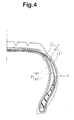
- Fig.4 shows another proposition, where two reinforcing rubber layers (g1) and (g2) are disposed between three plies (f1, f2 and f3) of the carcass (f) in the sidewall portion (d).
- the target load supporting power is the same level as of Fig.3.
- US-A-4 215 735 shows a pneumatic tyre according to the preamble of claim 1.
- the crown reinforcing rubber layer and carcass plies disposed radially inside thereof display strong resistance to bending deformation that would otherwise make the tread centre become hollow. Therefore, the tyre shoulder portions or buttress portions are prevented from contacting the ground when the tyre is punctured, and ground pressure is maintained even in the tread centre. As the bending deformation of the tread portion is minimised, it becomes possible to greatly reduce the volume of the side reinforcing rubber layer in comparison with the prior arts.
- the reinforcing rubber layers are made of a low heat generation rubber having a complex elastic modulus of 8 to 15 Mpa, and a loss tangent of 0.03 to 0.08.
- the complex elastic modulus of the side reinforcing rubber layer is preferably less than the complex elastic modulus of the crown reinforcing rubber layer.
- the axial width of the crown reinforcing rubber layer is preferably 0.7 to 1.2 times the ground contacting width.
- the radial extent of the side reinforcing rubber layer is preferably 0.2 to 1.2 times the ground contacting width.
- the thickness of the crown reinforcing rubber layer gradually decreases towards its axial ends from the centre, and the maximum thickness is preferably in the range of from 2 to 10%, more preferably 2.5 to 6% of the ground contacting width.
- the ground contacting width is defined as the maximum axial width of the ground contacting region when the tyre is mounted on a standard rim, inflated to normal pressure and loaded with a standard load which are specified by standardising organisation such as JATMA (Japan), TRA (USA), ETRTO (Europe) and the like.
- pneumatic tyres according to the present invention are shown in a normal inflated condition in which the tyre is mounted on its standard rim and inflated to standard pressure but loaded with no tyre load.
- the tyre comprises a tread portion 2, a pair of axially spaced bead portions 4 each with a bead core 5 therein, a pair of sidewall portions 3 extending between the tread edges and the bead portions, a carcass 6 extending between the bead portions 4, and a belt 7 disposed radially outside the carcass 6 in the tread portion.
- the belt 7 comprises two plies 7A and 7B of cords laid for example at an angle of 10 to 35 degrees to the tyre equator C, the cords in each ply being parallel with each other but crosswise to the next ply.
- high modulus cords e.g. steel cords, aromatic polyamide and the like are preferably used.
- the carcass 6 comprises at least three plies 6A, 6B, 6C and 6D of cords arranged radially at an angle of 90 to 65 degrees with respect to the tyre equator C.
- steel cords and organic fibre cords e.g. polyester, rayon and the like can be used.
- the carcass ply 6C is outermost and extends between the bead portions 4 and is turned up around the bead cores 5 from the axially inside to outside of the tyre to form a pair of turnup portions 6b and a main portion 6a therebetween.
- the carcass ply 6A is innermost and the carcass ply 6B is therebetween.
- the plies 6A and 6B extend between the bead portions 4 but they are not turned up around the bead cores 5 and terminate in the respective bead portions and axially inside the bead cores 5.
- a bead apex 12 made of a hard rubber compound is disposed between the main portion 6a and turnup portion 6b of the carcass ply 6C.
- the bead apex 12 tapers radially outwardly from the bead core 5.
- the tread portion 2 is provided between the radially outermost carcass ply 6C and the radially inner next carcass ply 6B, 6D with a crown reinforcing rubber layer 9.
- the axial width CL of the crown reinforcing rubber layer 9 is 0.7 to 1.2 times the ground contacting width TW.
- the thickness of the crown reinforcing rubber layer 9 gradually decreases towards its axial ends from the centre or the tyre equator C.
- the thickness T1 at the tyre equator C is in the range of from 2 to 10%, more preferably 2.5 to 6% of the ground contacting width TW.
- the assembly of the crown reinforcing rubber layer 9 and the carcass plies adjacent radially outwardly and inwardly thereto can resist bending deformation.
- the resistance to the bending deformation is sufficient to prevent the buttress regions 8 from contacting with the ground, without deteriorating the ride comfort or increasing the tyre weight, because the number of the carcass plies is larger radially inside of the Crown reinforcing rubber layer 9, that is, on the side where a large tensile stress is produced when the tyre on a car is punctured, than the other side, and further, the thickness is increased in the centre where the compressive stress is larger when the tyre is punctured.
- the above-mentioned sidewall portion 3 is provided between the innermost carcass ply 6A and the axially outer next carcass ply 6B with a side reinforcing rubber layer 10.
- the side reinforcing rubber layer 10 tapers towards its radially outer end 10A and inner end 10B.
- the maximum thickness T2 lying in the middle thereof in the tyre radial direction is set in the range of from 2 to 10% more preferably 2.5 to 6% of the ground contacting width TW.
- the maximum thickness T2 occurs in the maximum tyre section width position M.
- the radial extent SL of the side reinforcing rubber layer lo measured radially between the radially outer end 10A and inner end 10B is 0.2 to 1.2 times, more preferably 0.3 to 0.5 times the ground contacting width TW.
- the radially inner end 10B of the side reinforcing rubber layer 10 overlaps the radially outer end of the bead apex 12.
- Fig.1 the radially outer end 10A of the side reinforcing rubber layer 10 overlaps the axial ends of the crown reinforcing rubber layer 9 and the belt 7.
- the resistance to bending deformation is effectively increased to prevent the inner surface of the sidewall portion 3 from rubbing against itself and thus acts to prevent heat damage, without deteriorating ride comfort or increasing the tyre weight.
- the number of the carcass plies is larger axially outside the side reinforcing rubber layer 10, that is, on the side where a large tensile stress is produced when the tyre on a car is punctured, than the other side, and further, the thickness is increased in the centre where the compressive stress is larger when the tyre is punctured.
- the crown reinforcing rubber layer 9 is disposed and at least two carcass plies are disposed along the axially outside of the side reinforcing rubber layer 10, it is possible to utilise less volume for side reinforcing rubber layer 10 than in the prior art, and thus a remarkable tyre weight reduction is possible in comparison with such prior arts.
- the thickness T2 is less than 2% of TW, the resistance to bending deformation of the side reinforcing rubber layer 10 becomes insufficient. If the thickness T2 is more than 10% of TW, heat generation tends to increase to decrease the durability and also the ride comfort is liable to deteriorate.
- the crown reinforcing rubber layer 9 and the side reinforcing rubber layer 10 are made of a low-heat-generation rubber whose complex elastic modulus E* is 8 to 15 Mpa or more preferably 8 to 12 Mpa, and loss tangent (tan ⁇ ) is 0.03 to 0.08 or more preferably 0.05 to 0.08.
- the tread portion 2 and sidewall portion 3 are provided with the bending rigidity necessary for long-distance run flat use, maintaining ride comfort to some degree.
- the complex elastic modulus E* is less than 8 Mpa, the bending rigidity becomes insufficient. If the complex elastic modulus E* is more than 15 Mpa, the ride comfort during normal running is liable to be deteriorated.
- loss tangent (tan ⁇ ) is more than 0.08, the heat generation increases and the run flat ability decreases. If the loss tangent (tan ⁇ ) is less than 0.03, the ride comfort tends to deteriorate.
- the reinforcing rubber layer disposed nearer to the bead portion 4 has a smaller complex elastic modulus E*.
- the complex elastic modulus E1* of the crown reinforcing rubber layer 9 is 12 Mpa
- the complex elastic modulus E2* of the side reinforcing rubber layer 10 is 8 Mpa.
- reinforcing rubber layers 9, 10 are provided, since only one carcass ply is turned-up in the bead portion excessive increase in bending rigidity near the bead portions is avoided and ride comfort in normal use is maintained.
- the complex elastic modulus E* and the loss tangent (tan ⁇ ) are measured with a viscoelastic spectrometer of IWAMOTO SEISAKUSYO make using a specimen of 4 mm width X 30 mm length X 1.5 mm thickness.
- the measuring conditions are as follows:
- the carcass 6 in addition to the above-mentioned carcass plies 6A-6C, the carcass 6 further comprises a carcass ply 6D which is disposed between the carcass plies 6C and 6B.
- the carcass ply 6D is not turned up and terminates in the lower sidewall portion, though the carcass plies 6A and 6B are terminated in the bead portion as explained above.
- the terminal ends of the carcass plies which are not turned up are such that the axially inner the carcass ply position, the radially inner the terminal end position.
- a buttress reinforcing rubber layer 11 is further disposed between the carcass plies 6B and 6D in the buttress region 8.
- the radially outer end 10A of the side reinforcing rubber layer 10 is disposed at a relatively lower height in comparison with the former example and thus spaced apart from the axial end 9E of the crown reinforcing rubber layer 9. In this space, the buttress reinforcing rubber layer 11 is disposed. As shown in Fig.2, both the ends are tapered and overlap with the axial end 9E of the crown reinforcing rubber layer 9 and the radial outer end 10A of the side reinforcing rubber layer 10.
- the complex elastic modulus E3* and loss tangent (tan ⁇ ) of the buttress reinforcing rubber layer 11 are also set in the same ranges as for the crown and side reinforcing rubber layers 9 and 10. It is preferable for the ride comfort in normal use to gradually decrease the complex elastic modulus from the tyre equator toward the bead portion, that is, E1* > E3* > E2*.
- the positions of the reinforcing rubber layers 9, 11, 10 are changed from outside to inside of the tyre within the thickness of the carcass 6.
- the number of the carcass plies adjacent to the outside of the reinforcing rubber layer is gradually increased, but the number of the carcass plies adjacent to the inside of the reinforcing rubber layer is gradually decreased.
- the buttress region 8 is effectively reinforced by the assembly of the buttress reinforcing rubber layer 11, two carcass plies 6C and 6D adjacent to the outside thereof and two carcass plies 6A and 6B adjacent to the inside thereof which shows strong resistance against both the inward and outward bending deformation.
- This arrangement is suitable for application in pneumatic tyres for relatively heavy vehicles such as light truck, recreational vehicle and the like, and also real heavy duty vehicles such as buses, trucks and the like.
- test car Japanese 4000cc car provided on all the wheels with test tyres in which the front right tyre is decreased to zero pressure was run at a speed of 80 km/H, and the running distance until the tyre was broken was measured.
Landscapes
- Engineering & Computer Science (AREA)
- Mechanical Engineering (AREA)
- Tires In General (AREA)
Claims (5)
- Luftreifen, umfassend einen Laufstreifenabschnitt (2), zwei Seitenwandabschnitte (3), zwei Wulstabschnitte (4), eine Karkasse (6) mit mindestens drei radialen Lagen (6A, 6B, 6C, 6D), die sich jeweils zwischen den Wulstabschnitten (4) durch den Laufstreifenabschnitt (2) und die Seitenwandabschnitte (3) erstrecken, wobei der Laufstreifenabschnitt (2) zwischen der radial äußersten Karkasslage (6C) und der radial inneren nächsten Karkasslage (6B, 6D) mit einer Kronenverstärkungsgummischicht (9) versehen ist, so dass mindestens zwei Karkasslagen (6B, 6C; 6B; 6C, 6D) radial innerhalb der Kronenverstärkungsgummischicht (9) angeordnet sind, wobei die Dicke der Kronenverstärkungsgummischicht (9) allmählich in Richtung ihrer axialen Enden von der Mitte aus abnimmt, und jeder Seitenwandabschnitt (3) mit einer Seitenverstärkungsgummischicht (10) versehen ist, so dass mindestens zwei Karkasslagen (6B, 6C; 6B, 6C, 6D) axial außerhalb der Seitenverstärkungsgummischicht (10) angeordnet sind, wobei sich jede Seitenverstärkungsgummischicht (10) in Richtung ihres radial äußeren Endes (10A) und inneren Endes (10B) verjüngt, dadurch gekennzeichnet, dass jede Seitenverstärkungsgummischicht (10) zwischen der axial innersten Karkasslage (6A) und der axial äußeren nächsten Karkasslage (6B) vorgesehen ist.
- Luftreifen nach Anspruch 1, dadurch gekennzeichnet, dass jeder Wulstabschnitt (4) mit einem Wulstkern (5) versehen ist, und dass die radial äußerste Karkasslage (6C, 6D) um die Wulstkerne (5) in den Wulstabschnitten (4) umgeschlagen ist, um zwei Umschlagabschnitte (6b) und einen Hauptabschnitt (6a) dazwischen zu definieren, aber die restlichen Karkasslagen (6A, 6B) nicht umgeschlagen sind, sondern axial innerhalb des Hauptabschnittes (6a) der äußersten Karkasslage (6C, 6D) enden.
- Luftreifen nach Anspruch 1 oder 2, dadurch gekennzeichnet, dass die Verstärkungsgummischichten (9, 10) aus einem wenig Wärme erzeugenden Gummi mit einem komplexen Elastizitätsmodul von 8 bis 15 MPa und einem Verlusttangens von 0,03 bis 0,08 mit den folgenden Messbedingungen hergestellt sind: Temperatur: 70°C, Frequenz: 10 Hz, Anfangsdehnung: 10 % und dynamische Verzerrung plus/minus 2 %.
- Luftreifen nach Anspruch 1, 2 oder 3, dadurch gekennzeichnet, dass der komplexe Elastizitätsmodul der Seitenverstärkungsgummischicht (10) kleiner als der komplexe Elastizitätsmodul der Kronenverstärkungsgummischicht (9) ist.
- Luftreifen nach Anspruch 1, 2, 3 oder 4, dadurch gekennzeichnet, dass die Karkasse (6) vier Lagen (6A, 6B, 6C, 6D) umfasst, und ferner eine Stützverstärkungsgummischicht (11) zwischen der Kronenverstärkungsgummischicht (9) und jeder der Seitenverstärkungsgummischichten (11) vorgesehen ist, so dass die Karkasse (6) zwischen den vier Lagen (6A, 6B, 6C, 6D) mit den Verstärkungsgummischichten (9, 10, 11) versehen ist, die, entlang der Karkasse (6) vom Reifenäquator (C) zu den Wulstabschnitten (4) betrachtet, ihre Positionen von der Außenseite zur Innenseite des Reifens verändern.
Applications Claiming Priority (3)
| Application Number | Priority Date | Filing Date | Title |
|---|---|---|---|
| JP310938/96 | 1996-11-21 | ||
| JP08310938A JP3079049B2 (ja) | 1996-11-21 | 1996-11-21 | 空気入りタイヤ |
| JP31093896 | 1996-11-21 |
Publications (3)
| Publication Number | Publication Date |
|---|---|
| EP0844110A2 EP0844110A2 (de) | 1998-05-27 |
| EP0844110A3 EP0844110A3 (de) | 1999-10-27 |
| EP0844110B1 true EP0844110B1 (de) | 2002-07-03 |
Family
ID=18011201
Family Applications (1)
| Application Number | Title | Priority Date | Filing Date |
|---|---|---|---|
| EP97309294A Expired - Lifetime EP0844110B1 (de) | 1996-11-21 | 1997-11-19 | Luftreifen |
Country Status (3)
| Country | Link |
|---|---|
| EP (1) | EP0844110B1 (de) |
| JP (1) | JP3079049B2 (de) |
| DE (1) | DE69713715T2 (de) |
Cited By (1)
| Publication number | Priority date | Publication date | Assignee | Title |
|---|---|---|---|---|
| US7048339B2 (en) | 2002-04-26 | 2006-05-23 | N.V. Bekaert S.A. | Force-limiting energy absorber |
Families Citing this family (25)
| Publication number | Priority date | Publication date | Assignee | Title |
|---|---|---|---|---|
| JP3335112B2 (ja) * | 1997-10-20 | 2002-10-15 | 住友ゴム工業株式会社 | ランフラットタイヤ |
| US6338374B1 (en) | 1998-03-26 | 2002-01-15 | The Goodyear Tire & Rubber Company | Runflat tire with fabric underlay and tread insert |
| GB2349124B (en) * | 1998-03-26 | 2002-04-24 | Goodyear Tire & Rubber | Fabric underlay and tread insert for improved tread rigidity of runflat tire |
| US6631748B1 (en) | 1998-07-06 | 2003-10-14 | The Goodyear Tire & Rubber Company | Sidewall with insert construction for runflat tire |
| WO2000001543A1 (en) * | 1998-07-06 | 2000-01-13 | The Goodyear Tire & Rubber Company | Improved sidewall with insert construction for runflat tire |
| BR9903977A (pt) * | 1998-09-09 | 2000-10-10 | Goodyear Tire & Rubber | Pneumático de operação plana |
| WO2000020236A1 (en) * | 1998-10-01 | 2000-04-13 | The Goodyear Tire & Rubber Company | Improved construction for runflat tire |
| US6619354B1 (en) * | 1998-12-17 | 2003-09-16 | Bridgestone Corporation | Run flat pneumatic tire with shoulder cushion rubber layer loss tangent less than carcass coating rubber loss tangent |
| DE19859157A1 (de) * | 1998-12-21 | 2000-06-29 | Dunlop Gmbh | Fahrzeugluftreifen |
| JP4497602B2 (ja) * | 1999-03-08 | 2010-07-07 | 株式会社ブリヂストン | 乗用車用空気入りタイヤ |
| US7418988B2 (en) | 1999-12-10 | 2008-09-02 | Michelin Recherche Et Technique S.A. | Non-pneumatic tire |
| DE69929903T2 (de) | 1999-12-10 | 2006-09-28 | Michelin Recherche Et Technique S.A. | Elastischer selbsttragender reifen |
| US6983776B2 (en) | 1999-12-10 | 2006-01-10 | Michelin Recherche Et Technique S.A. | Structurally supported resilient tire with bias ply carcass |
| JP4176473B2 (ja) * | 2000-12-22 | 2008-11-05 | ピレリ・タイヤ・ソチエタ・ペル・アツィオーニ | 車両ホイール用自己担持タイヤおよびその製造方法 |
| BR0116393A (pt) * | 2000-12-22 | 2004-03-02 | Pirelli | Pneu auto-suportante para rodas de veìculo, roda com pneu para veìculos, e, método para fabricar um pneu auto-suportante para rodas de veìculo |
| PL358495A1 (en) * | 2001-04-16 | 2004-08-09 | Societe De Technologie Michelin | Structurally supported resilient tire with bias ply carcass |
| US6938659B2 (en) * | 2002-09-19 | 2005-09-06 | The Goodyear Tire & Rubber Company | Runflat tire having crown-reinforcing insert extending into the sidewalls |
| JP2004299639A (ja) * | 2003-04-01 | 2004-10-28 | Yokohama Rubber Co Ltd:The | 空気入りタイヤ |
| US7021350B2 (en) * | 2004-04-06 | 2006-04-04 | The Goodyear Tire & Rubber Company | Pneumatic run-flat tire with porous elastomeric layer |
| EP1676730B1 (de) * | 2004-12-31 | 2008-04-16 | Societe de Technologie Michelin STM | Notlaufreifen mit getrennten Karkasslagen im Kronenbereich |
| JP5134249B2 (ja) * | 2006-02-07 | 2013-01-30 | 住友ゴム工業株式会社 | ランフラットタイヤ |
| JP6411059B2 (ja) * | 2014-04-23 | 2018-10-24 | 株式会社ブリヂストン | 乗用車用サイド補強型ランフラットラジアルタイヤ |
| JP6759903B2 (ja) * | 2016-09-09 | 2020-09-23 | 住友ゴム工業株式会社 | 重荷重用タイヤ |
| CN110799356B (zh) * | 2017-06-27 | 2021-11-30 | 米其林集团总公司 | 轻质轮胎 |
| FR3102092A1 (fr) * | 2019-10-22 | 2021-04-23 | Compagnie Generale Des Etablissements Michelin | Pneumatique à bande de roulement perfectionnée |
Family Cites Families (3)
| Publication number | Priority date | Publication date | Assignee | Title |
|---|---|---|---|---|
| JPS53126601A (en) * | 1977-04-08 | 1978-11-06 | Bridgestone Corp | Pneumatic safety tire |
| FR2425334A1 (fr) * | 1978-05-11 | 1979-12-07 | Kleber Colombes | Pneumatique de securite |
| JPS5893606A (ja) * | 1981-11-27 | 1983-06-03 | Sumitomo Rubber Ind Ltd | 自動二輪車 |
-
1996
- 1996-11-21 JP JP08310938A patent/JP3079049B2/ja not_active Expired - Fee Related
-
1997
- 1997-11-19 DE DE69713715T patent/DE69713715T2/de not_active Expired - Fee Related
- 1997-11-19 EP EP97309294A patent/EP0844110B1/de not_active Expired - Lifetime
Cited By (1)
| Publication number | Priority date | Publication date | Assignee | Title |
|---|---|---|---|---|
| US7048339B2 (en) | 2002-04-26 | 2006-05-23 | N.V. Bekaert S.A. | Force-limiting energy absorber |
Also Published As
| Publication number | Publication date |
|---|---|
| DE69713715T2 (de) | 2002-11-07 |
| JP3079049B2 (ja) | 2000-08-21 |
| JPH10151917A (ja) | 1998-06-09 |
| EP0844110A2 (de) | 1998-05-27 |
| DE69713715D1 (de) | 2002-08-08 |
| EP0844110A3 (de) | 1999-10-27 |
Similar Documents
| Publication | Publication Date | Title |
|---|---|---|
| US5988247A (en) | Pneumatic tire with crown reinforcing rubber layer and side reinforcing rubber layers | |
| EP0844110A2 (de) | Luftreifen | |
| EP1481822B1 (de) | Radialer Luftreifen | |
| EP4094958B1 (de) | Schwerlastluftreifen | |
| US7036541B2 (en) | Pneumatic tire | |
| EP1095797B1 (de) | Luftreifen | |
| KR100551869B1 (ko) | 공기 레이디얼 플라이 타이어 | |
| EP0911188B1 (de) | Notlaufreifen | |
| EP0424155A2 (de) | Radialer Luftreifen | |
| US9038682B2 (en) | Pneumatic tire | |
| US4884610A (en) | Depressed radial tire | |
| US9987883B2 (en) | Pneumatic tire | |
| EP0850788B1 (de) | Radialer Luftreifen | |
| EP0346106A1 (de) | Luftreifen | |
| EP4116112B1 (de) | Schwerlastreifen | |
| AU704770B2 (en) | Pneumatic radial tire | |
| EP0890452B1 (de) | Luftreifen | |
| EP1186450B1 (de) | Notlaufreifen | |
| EP1580038B1 (de) | Luftreifen mit Notlaufeigenschaften | |
| EP2261060B1 (de) | Motorradreifen | |
| EP4116109B1 (de) | Schwerlastreifen | |
| US5928445A (en) | Pneumatic tires with specified profile | |
| EP4559698B1 (de) | Luftreifen | |
| EP1013477B1 (de) | Luftreifen | |
| JP2025102226A (ja) | 空気入りタイヤ |
Legal Events
| Date | Code | Title | Description |
|---|---|---|---|
| PUAI | Public reference made under article 153(3) epc to a published international application that has entered the european phase |
Free format text: ORIGINAL CODE: 0009012 |
|
| AK | Designated contracting states |
Kind code of ref document: A2 Designated state(s): DE FR GB |
|
| AX | Request for extension of the european patent |
Free format text: AL;LT;LV;MK;RO;SI |
|
| PUAL | Search report despatched |
Free format text: ORIGINAL CODE: 0009013 |
|
| AK | Designated contracting states |
Kind code of ref document: A3 Designated state(s): AT BE CH DE DK ES FI FR GB GR IE IT LI LU MC NL PT SE |
|
| AX | Request for extension of the european patent |
Free format text: AL;LT;LV;MK;RO;SI |
|
| 17P | Request for examination filed |
Effective date: 20000316 |
|
| AKX | Designation fees paid |
Free format text: DE FR GB |
|
| GRAG | Despatch of communication of intention to grant |
Free format text: ORIGINAL CODE: EPIDOS AGRA |
|
| 17Q | First examination report despatched |
Effective date: 20010828 |
|
| GRAG | Despatch of communication of intention to grant |
Free format text: ORIGINAL CODE: EPIDOS AGRA |
|
| GRAH | Despatch of communication of intention to grant a patent |
Free format text: ORIGINAL CODE: EPIDOS IGRA |
|
| GRAH | Despatch of communication of intention to grant a patent |
Free format text: ORIGINAL CODE: EPIDOS IGRA |
|
| GRAA | (expected) grant |
Free format text: ORIGINAL CODE: 0009210 |
|
| AK | Designated contracting states |
Kind code of ref document: B1 Designated state(s): DE FR GB |
|
| REF | Corresponds to: |
Ref document number: 69713715 Country of ref document: DE Date of ref document: 20020808 |
|
| ET | Fr: translation filed | ||
| PLBE | No opposition filed within time limit |
Free format text: ORIGINAL CODE: 0009261 |
|
| STAA | Information on the status of an ep patent application or granted ep patent |
Free format text: STATUS: NO OPPOSITION FILED WITHIN TIME LIMIT |
|
| 26N | No opposition filed |
Effective date: 20030404 |
|
| PGFP | Annual fee paid to national office [announced via postgrant information from national office to epo] |
Ref country code: GB Payment date: 20061115 Year of fee payment: 10 |
|
| PGFP | Annual fee paid to national office [announced via postgrant information from national office to epo] |
Ref country code: FR Payment date: 20071108 Year of fee payment: 11 |
|
| GBPC | Gb: european patent ceased through non-payment of renewal fee |
Effective date: 20071119 |
|
| PG25 | Lapsed in a contracting state [announced via postgrant information from national office to epo] |
Ref country code: GB Free format text: LAPSE BECAUSE OF NON-PAYMENT OF DUE FEES Effective date: 20071119 |
|
| PGFP | Annual fee paid to national office [announced via postgrant information from national office to epo] |
Ref country code: DE Payment date: 20081114 Year of fee payment: 12 |
|
| REG | Reference to a national code |
Ref country code: FR Ref legal event code: ST Effective date: 20090731 |
|
| PG25 | Lapsed in a contracting state [announced via postgrant information from national office to epo] |
Ref country code: DE Free format text: LAPSE BECAUSE OF NON-PAYMENT OF DUE FEES Effective date: 20100601 |
|
| PG25 | Lapsed in a contracting state [announced via postgrant information from national office to epo] |
Ref country code: FR Free format text: LAPSE BECAUSE OF NON-PAYMENT OF DUE FEES Effective date: 20081130 |