EP0844143A1 - Gehäuse mit einer Kammer zur Aufnahme eines zusammengefalteten und aufblasbaren Luftsackes - Google Patents
Gehäuse mit einer Kammer zur Aufnahme eines zusammengefalteten und aufblasbaren Luftsackes Download PDFInfo
- Publication number
- EP0844143A1 EP0844143A1 EP97120039A EP97120039A EP0844143A1 EP 0844143 A1 EP0844143 A1 EP 0844143A1 EP 97120039 A EP97120039 A EP 97120039A EP 97120039 A EP97120039 A EP 97120039A EP 0844143 A1 EP0844143 A1 EP 0844143A1
- Authority
- EP
- European Patent Office
- Prior art keywords
- flap
- airbag
- housing
- main
- housing according
- Prior art date
- Legal status (The legal status is an assumption and is not a legal conclusion. Google has not performed a legal analysis and makes no representation as to the accuracy of the status listed.)
- Granted
Links
- 238000009434 installation Methods 0.000 claims description 3
- 208000027418 Wounds and injury Diseases 0.000 description 6
- 230000006378 damage Effects 0.000 description 6
- 208000014674 injury Diseases 0.000 description 6
- 230000000694 effects Effects 0.000 description 5
- 238000000034 method Methods 0.000 description 3
- 230000003111 delayed effect Effects 0.000 description 2
- 230000001960 triggered effect Effects 0.000 description 2
- 230000003313 weakening effect Effects 0.000 description 2
- 208000035874 Excoriation Diseases 0.000 description 1
- 230000007958 sleep Effects 0.000 description 1
Images

Classifications
-
- B—PERFORMING OPERATIONS; TRANSPORTING
- B60—VEHICLES IN GENERAL
- B60R—VEHICLES, VEHICLE FITTINGS, OR VEHICLE PARTS, NOT OTHERWISE PROVIDED FOR
- B60R21/00—Arrangements or fittings on vehicles for protecting or preventing injuries to occupants or pedestrians in case of accidents or other traffic risks
- B60R21/02—Occupant safety arrangements or fittings, e.g. crash pads
- B60R21/16—Inflatable occupant restraints or confinements designed to inflate upon impact or impending impact, e.g. air bags
- B60R21/20—Arrangements for storing inflatable members in their non-use or deflated condition; Arrangement or mounting of air bag modules or components
- B60R21/215—Arrangements for storing inflatable members in their non-use or deflated condition; Arrangement or mounting of air bag modules or components characterised by the covers for the inflatable member
- B60R21/2165—Arrangements for storing inflatable members in their non-use or deflated condition; Arrangement or mounting of air bag modules or components characterised by the covers for the inflatable member characterised by a tear line for defining a deployment opening
- B60R21/21656—Steering wheel covers or similar cup-shaped covers
Definitions
- the invention relates to a housing with a chamber to accommodate a folded and inflatable Airbag that inflates especially the driver of a vehicle before an impact on vehicle interior parts protects, with one in the main direction of deployment of the airbag, by a hinged Airbag cover closed main opening, being the airbag cover has a main flap that is on one of its edges hinged on the housing is.
- airbag also called airbag
- the airbag is folded up in a chamber with one aligned to the passenger compartment and by a Cover sealed main openings housed.
- the size of the chamber is the dimensions of the airbag when folded Condition adjusted.
- There is a cover one or more flaps, each with one Edge are hinged to the housing forming the chamber.
- the flaps form a limit gap in one the housing opening forming the main opening. There is a tearable connection along the border gap provided by the unfolding airbag is separated.
- the arrangement of the airbag, its size and speed, with which it is inflated is coordinated on a normal tall person who due to his arm length maintains a certain distance from the steering wheel.
- an accident e.g. B. a frontal impact
- the upper body of this person is created by the Restraint belt delayed in relation to the passenger compartment, so that the head only hits the airbag when it is fully unfolded and filled with gas.
- This is the ideal case.
- the development of a restraint system with Airbag can not only refer to this ideal case will; rather so-called out-of-position conditions (OOP) are considered, which e.g. B. for small People or with normal height in a bent position available. In these situations it can be expected that the body or head of the occupant is not inflated but on the airbag that is still unfolding hits, whereby much greater forces act than in the first Case.
- OOP out-of-position conditions
- the invention therefore proposes to provide a main flap for covering the driver's airbag, which almost completely covers the opening and is struck with its upper edge on the housing, so that it folds up when the airbag unfolds and forms a guide for him.
- the opening movement of the main flap is delayed, so that it can perform the function of a guiding surface.
- the sequence of the opening movement can be controlled z. B. by adjusting the weight of the flap or by adjusting the stiffness of the hinge between Flap and housing.
- the guiding effect occurs especially when the Air bag is a radially expanding air bag.
- the conductivity of the main flap can still be supported be that in addition a free path of development is made available down. This will do so achieved that in addition to the main flap one or more Auxiliary flaps are provided, the openings are covered in to the installation position, delimiting the chamber downwards Cover the side wall.
- the side flaps can on the Main flap or hinged to the side wall be, in the second case between secondary flap and the main flap has a tearable connection.
- the chamber for receiving the airbag is thus through limited a side wall that is approximately perpendicular to Main flap runs.
- This side wall has openings which are closed by the side flaps.
- the side flaps will crash, depending on how they are attached are pushed up or down so that they were at a very early stage in the development of the Airbags open a downward path for him. Supported by the guiding function described above Main flap is achieved in that the airbag is in the initial stage of development towards the chest of the driver.
- openings are especially important when the driver with his body on the main door then the unfolding pressure can pass through the openings at least partially derived in the side wall downwards so that those acting on the driver's body Forces are minimized.
- downward sidewall are intended not only side walls are understood, their surface normal are aligned exactly downwards, but also sidewalls whose surface normals are only one have downward facing component.
- the side wall is substantially perpendicular to the Main flap run and therefore slightly forward, accordingly the inclination of the steering wheel in the vehicle interior, be aligned.
- the term also includes sidewalls, whose surface normals are directed to the side Have component.
- One embodiment of the invention provides that the lower one Edge of the housing runs in an arc, the Traces the curve of the lower edge of the main flap.
- the side wall has side by side and one inside the other merging openings on through several abutting Secondary flaps are covered.
- a main flap in the form of one would also be conceivable Triangle, the base edge of which is at the top of the airbag housing is struck. Extend parallel to the two legs themselves side walls that go to the side and down are aligned. This arrangement is particularly useful then when the steering wheel additionally has a down directional strut is attached to the steering wheel hub, so that the two secondary flaps on the left and right of the lower one Strut.
- the flap opens evenly so that the airbag is even with respect to a vertical axis unfolded. It should be avoided that the airbag on the one hand more developed than on the other hand because then the intended effect namely the dampening impact on the chest of one person in OOP condition not fully reached can be. With a conventional approach is the even deployment of the airbag not so important since it is only critical there arrives that the airbag unfolds at all.
- Tear line in at least approximately equally long sections to divide.
- the first two sections are in the end areas of the tear line, i.e. end at the hinge.
- the third area is in the middle of the Tear line, e.g. B. in the lower arch of a U-shaped Tear line.
- the weakening of the tear line can now be made in the first two Areas is significantly weaker than in the third area or the other way around. If the first two areas are weaker than the third area, results when inflating of the airbag the following picture.
- the tear line burst along the weaker areas, up to one side the hinge or on the other Side of the stronger area is reached.
- the ripping process does not become even in the two areas expire, which can be tolerated because the flap is still attached in the third area and therefore not yet Opening process is initiated.
- If the crack z. B. in first area reaches the third area it will first not continued because of the compressive forces of the airbag first cause the tear line of the second Area is completely torn open.
- the crack stretches thus initially in both areas up to the respective Limit point at the third area. Only now the increasing pressure in the airbag that also the tear line bursts in the third area, starting in the two border points.
- Airbag cover 6 is closed.
- the airbag cover consists of a main flap 7 and several Secondary flaps 8, 9, 10. While the main flap 7 almost completely covers the area of the opening that is in or parallel to the steering wheel level and the Forms main opening, the secondary flaps 8, 9, 10 cover one Area of the opening, which is arched below the Main opening runs and is essentially vertical extends to the main opening.
- main and secondary opening can you imagine an open pot, where the main opening area is limited by the edge of the pot becomes.
- the secondary opening is formed by a Part of the side wall of the pot is cut away: the Opening area is curved and through the cut edges the cut-off edge line of the main opening.
- the housing is formed through an approximately U-shaped wall section and one that closes the open end of the U. straight wall section.
- the main flap 7 has one Form adapted to the wall, with the upper straight Section 11 of the flap hinge-like on the hub cover 16 is attached.
- the dash-dotted line 13 indicates a tear line over the boundary gap between the main flap 7 and the hub cover or between the main flap 7 and the secondary flaps 8, 9, 10, which are approximately vertical stand to the main flap 7 and at its rear edges are hinged to the hub cover, so that they fold down (arrows 14).
- the secondary flaps 8, 9, 10 cover an opening area from approx. 135 °. They meet with their short sides and with their front edges to the Main flap 7 on. As already explained above is, the secondary flaps 8, 9, 10 can also with the main flap 7 are connected hinge-like, so that after would fold away upstairs.
- FIG. 3 shows a cross section along the line II - II.
- a housing 22 for the airbag can be seen. This housing is by a cap-like hub cover 16, in the main and secondary flaps 8, 9, 10 are integrated, locked.
- the main flap 7 is located immediately above the housing 22.
- the two secondary flaps 24, 25 run approximately perpendicular to the main flap 7 and are aligned obliquely to the side according to the V-shape.
- the side flaps 24, 25 to post One possibility is in the left side of FIG. 3.
- the tear line 13 is in the boundary gap between the secondary flap 24 and the main flap 7. Accordingly, the in The bottom edge of the side flap 24 is articulated struck on the hub cover.
- the secondary flap 25 via a hinge 27 connected to the main flap 7 and the tear line 28 is located in the boundary gap between the secondary flap 25 and the hub cover.
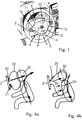
- FIGS. 4a and 4b show a conventional cover of a driver airbag with two approximately equal flaps 30, 31 that face up or fold away below.
- the airbag 32 expands rapidly Direction of the main unfolding direction, so that it with full force of the head 33 of a driver in an OOP position meets what z. B. skin abrasions can be.
- Fig. 4b The effect of the proposal according to the invention, in particular to provide a single main flap 7 for the main opening, which completely covers them and upwards folds away, is shown in Fig. 4b, the one still not fully deployed airbag 32 shows.
- the main door 7 can not quickly enough from the unfolding airbag 32 be pushed upwards: it therefore forms one Guide surface 35, which in the illustrated initial phase of Unfolding the airbag down towards to the driver's upper body.
- a disability the airbag unfolds through a lower flap is not given. It only bulges in the final phase Air bag also towards the head 33, being muffles his head because he already has a part lost its force.
- the possibility of injury from People in OOP locations is therefore due to the fact reduces the full deployment power of the airbag is not passed directly to the head 33, but beforehand partially taken up by the driver's upper body 36 becomes.
- FIG. 5 schematically shows a tear line, which is U-shaped here, but also z. B. can be V-shaped. It is crucial that the tear line is divided into three areas, namely the areas a, b and c. These are roughly the same size and symmetrical arranged, areas a and b (first and second area) approximately along the legs of the U run and end at hinge 27 while the area c (third area) forms the bottom of the U and to the areas a and b in the border points A and B.
- Crucial is that the areas have different crack resistances exhibit. There are two options. Either the crack resistances are areas a and b the same size, but smaller than that of area c or vice versa.
- the crack begins in areas a and b or in area c. It is crucial that the crack process, no matter in which The area begins, initially at the boundary point A or B. stopped due to the discontinuity in the crack resistance, until the other limit point is reached. First then in the first case the crack settles in the area c and in the second area evenly in areas a and b away. In this way it becomes largely symmetrical Guaranteed course of tearing, so that the flap is pressed evenly.
Landscapes
- Engineering & Computer Science (AREA)
- Mechanical Engineering (AREA)
- Air Bags (AREA)
Abstract
Description
- Fig. 1:
- zeigt ein Armaturenbrett mit einem davor angeordneten Lenkrad, in dessen Nabe ein Airbag angeordnet ist, wobei das Lenkrad über zwei seitliche Streben mit der Nabe verbunden ist.
- Fig. 2:
- zeigt eine anders gestaltete Nabe eines Lenkrades und eine entsprechende anders geformte Abdeckklappe.
- Fig. 3:
- zeigt einen Querschnitt entlang der Linie III - III der Figur 2.
- Fig. 4a:
- zeigt skizzenhaft den Ausstoß eines Airbags aus einem Gehäuse mit herkömmlicher Klappe und
- Fig. 4b:
- zeigt dieselbe Situation bei einem Gehäuse mit einer Abdeckung gemäß der Erfindung und
- Fig. 5:
- zeigt eine schematische Darstellung einer Aufreißlinie.
- 1
- Armaturenbrett
- 2
- Lenkkranz
- 3
- Steg
- 4
- Steg
- 5
- Lenkradnabe
- 6
- Luftsackabdeckung
- 7
- Hauptklappe
- 8
- Nebenklappe
- 9
- Nebenklappe
- 10
- Nebenklappe
- 11
- Abschnitt
- 12
- Pfeil
- 13
- Linie
- 14
- Pfeil
- 15
- Steg
- 16
- Nabenabdeckung
- 20
- Grenzspalt
- 22
- Gehäuse
- 24
- Nebenklappe
- 25
- Nebenklappe
- 26
- Aufreißlinie
- 27
- Scharnier
- 28
- Aufreißlinie
- 30
- Klappe
- 31
- Klappe
- 32
- Airbag
- 33
- Kopf
- 35
- Leitfläche
- 36
- Oberkörper
Claims (10)
- Gehäuse mit einer Kammer zur Aufnahme eines zusammengefalteten und aufblasbaren Luftsackes, der aufgeblasen insbesondere den Fahrer eines Fahrzeuges vor einem Aufprall auf Fahrzeuginnenraumteile schützt, mit einer in die Hauptentfaltungsrichtung des Luftsackes ausgerichteten, durch eine aufklappbare Luftsackabdeckung (6) verschlossenen Hauptöffnung, wobei die Luftsackabdeckung (6) eine Hauptklappe (7) aufweist, die an einer ihrer Kanten über ein Scharnier am Gehäuse angeschlagen ist, dadurch gekennzeichnet, daß die Hauptklappe (7) an ihrer bezogen auf die Einbauposition oberen Kante mittels eines Scharniers am Gehäuse angeschlagen ist, so daß sie bei der Entfaltung des Luftsacks eine Leitfläche für ihn bildet.
- Gehäuse nach Anspruch 1 dadurch gekennzeichnet, daß die Luftsackabdeckung (6) mindestens eine an die Hauptklappe (7) anschließenden Nebenklappe (8, 9, 10; 24, 25) aufweist.
- Gehäuse nach Anspruch 2, dadurch gekennzeichnet, daß zumindest eine bezogen auf die Einbauposition nach unten gerichtete, die Kammer begrenzende Seitenwand eine Seitenöffnung aufweist, die von der oder den Nebenklappen (8, 9, 10; 24, 25) abgedeckt ist/sind.
- Gehäuse nach Anspruch 2, dadurch gekennzeichnet, daß die Nebenklappe (8, 9, 10; 24, 25) mittels eines Scharniers an die Hauptklappe (7) angeschlagen ist.
- Gehäuse nach Anspruch 2, dadurch gekennzeichnet, daß die Nebenklappen (8, 9, 10; 24, 25) mittels eines Scharniers an die Seitenwand angeschlagen sind.
- Gehäuse nach einem der vorhergehenden Ansprüche, dadurch gekennzeichnet, daß die Hauptklappe (7) ein gleichschenkliges Dreieck bildet, wobei die Basis des Dreiecks mittels eines Scharniers an das Gehäuse angeschlagen ist, und daß das Gehäuse eine linke und eine rechte Seitenwand aufweist, die in etwa parallel zu den Schenkeln des Dreiecks verlaufen und wobei in jede Seitenwand eine Nebenklappe (24, 25) eingesetzt ist.
- Gehäuse nach einem der Ansprüche 1 bis 5, dadurch gekennzeichnet, daß die untere Kante der Hauptklappe (7) bogenförmig verläuft und das Gehäuse eine Seitenwand aufweist, die dem Bogenverlauf folgt.
- Gehäuse nach einem der vorhergehenden Ansprüche, dadurch gekennzeichnet, daß der Grenzspalt zwischen der Luftsackabdeckung und einen sie umgehenden Rahmen eine Aufreißlinie aufweist, die in mindestens drei symmetrisch angeordnete Abschnitte aufgeteilt ist, wobei der dritte Bereich von einem ersten und zweiten Bereich eingeschlossen wird und zumindest der dritte Bereich gegenüber den beiden ersten Bereichen einen anderen Rißwiderstand aufweist.
- Gehäuse nach Anspruch 8, dadurch gekennzeichnet, daß der dritte Abschnitt einen größeren Rißwiderstand aufweist als die beiden ersten Bereiche.
- Gehäuse nach Anspruch 8, dadurch gekennzeichnet, daß der dritte Bereich einen kleineren Rißwiderstand aufweist als die beiden ersten Bereiche.
Applications Claiming Priority (2)
| Application Number | Priority Date | Filing Date | Title |
|---|---|---|---|
| DE19648136A DE19648136A1 (de) | 1996-11-21 | 1996-11-21 | Gehäuse mit einer Kammer zur Aufnahme eines zusammengefalteten und aufblasbaren Luftsackes |
| DE19648136 | 1996-11-21 |
Publications (2)
| Publication Number | Publication Date |
|---|---|
| EP0844143A1 true EP0844143A1 (de) | 1998-05-27 |
| EP0844143B1 EP0844143B1 (de) | 2002-10-02 |
Family
ID=7812307
Family Applications (1)
| Application Number | Title | Priority Date | Filing Date |
|---|---|---|---|
| EP97120039A Expired - Lifetime EP0844143B1 (de) | 1996-11-21 | 1997-11-15 | Gehäuse mit einer Kammer zur Aufnahme eines zusammengefalteten und aufblasbaren Luftsackes |
Country Status (3)
| Country | Link |
|---|---|
| EP (1) | EP0844143B1 (de) |
| DE (2) | DE19648136A1 (de) |
| ES (1) | ES2184019T3 (de) |
Cited By (3)
| Publication number | Priority date | Publication date | Assignee | Title |
|---|---|---|---|---|
| WO2000074981A1 (de) * | 1999-06-08 | 2000-12-14 | Takata-Petri Ag | Airbagmodul für lenkräder |
| WO2002014116A3 (de) * | 2000-08-11 | 2002-05-30 | Takata Petri Ag | Airbagmodul für ein kraftfahrzeuglenkrad |
| US7552940B2 (en) | 2004-03-26 | 2009-06-30 | Faurecia Innenraum Systeme Gmbh | Internal door cladding provided with a head and/or shoulder anti-shock airbag in the event of side collision and/or rollover and a vehicle provided with said internal door cladding |
Families Citing this family (4)
| Publication number | Priority date | Publication date | Assignee | Title |
|---|---|---|---|---|
| DE19905122A1 (de) * | 1999-02-01 | 2000-08-10 | Petri Ag | Airbageinheit mit einer Steuerung des Gassackaustrittes |
| DE102006052190A1 (de) | 2006-11-02 | 2008-05-08 | Takata-Petri Ag | Airbagmodul für ein Kraftfahrzeug |
| DE102014205149B4 (de) | 2014-03-19 | 2020-01-02 | Joyson Safety Systems Germany Gmbh | Abdeckkappe eines Airbagmodules |
| KR102452475B1 (ko) | 2020-08-26 | 2022-10-11 | 현대모비스 주식회사 | 차량용 운전석 에어백 장치 |
Citations (3)
| Publication number | Priority date | Publication date | Assignee | Title |
|---|---|---|---|---|
| JPH03258636A (ja) * | 1990-03-09 | 1991-11-18 | Mazda Motor Corp | 車体側部のエネルギ吸収構造 |
| EP0487753A1 (de) * | 1990-06-20 | 1992-06-03 | Takata Corporation | Deckelmodul für eine luftsackvorrichtung |
| JPH0761310A (ja) * | 1993-08-30 | 1995-03-07 | Toyoda Gosei Co Ltd | エアバッグ装置の蓋材 |
Family Cites Families (15)
| Publication number | Priority date | Publication date | Assignee | Title |
|---|---|---|---|---|
| JP2509277B2 (ja) * | 1988-02-09 | 1996-06-19 | 日産自動車株式会社 | 自動車のエアバッグ装置 |
| DE3835581A1 (de) * | 1988-10-19 | 1990-04-26 | Porsche Ag | Aufprallschutzeinrichtung fuer einen insassen eines kraftfahrzeuges |
| DE3837085A1 (de) * | 1988-11-01 | 1990-05-03 | Kolbenschmidt Ag | Gassack-aufprallschutzvorrichtung |
| JPH0694266B2 (ja) * | 1989-02-20 | 1994-11-24 | タカタ株式会社 | エアバッグ収納用カバー |
| DE59008420D1 (de) * | 1990-06-09 | 1995-03-16 | Petri Ag | Gehäuse für Gassack-Auffang-Schutzeinrichtungen von Kraftfahrzeugen. |
| DE4023555A1 (de) * | 1990-07-25 | 1991-07-25 | Daimler Benz Ag | Armaturentafel fuer kraftfahrzeuge |
| US5209510A (en) * | 1990-07-31 | 1993-05-11 | Nissan Motor Co., Ltd. | Airbag restraint system for motor vehicle |
| JPH04185551A (ja) * | 1990-11-19 | 1992-07-02 | Toyota Motor Corp | 自動車用エアバツグカバー |
| GB9122487D0 (en) * | 1991-10-23 | 1991-12-04 | Rolls Royce Motor Cars | Vehicle air-bag cover plate |
| DE4307969A1 (de) * | 1993-03-12 | 1994-09-15 | Trw Repa Gmbh | Fahrerseitiges Gassack-Rückhaltesystem für Fahrzeuge |
| JP2766775B2 (ja) * | 1993-03-23 | 1998-06-18 | ティーアールダブリュー・ヴィークル・セーフティ・システムズ・インコーポレーテッド | ハウジング組立体及び装置 |
| GB9315047D0 (en) * | 1993-07-20 | 1993-09-01 | Klippan Autoliv Snc | Improvements in or relating to a cover for an air-bag |
| US5385366A (en) * | 1993-09-07 | 1995-01-31 | General Motors Corporation | Air bag deflection shield |
| DE4438195C1 (de) * | 1994-10-26 | 1995-11-02 | Daimler Benz Ag | Lenkrad für ein Kraftfahrzeug |
| DE4442543A1 (de) * | 1994-11-30 | 1996-01-25 | Daimler Benz Ag | Gassackeinheit in einem Fahrzeug |
-
1996
- 1996-11-21 DE DE19648136A patent/DE19648136A1/de not_active Withdrawn
-
1997
- 1997-11-15 EP EP97120039A patent/EP0844143B1/de not_active Expired - Lifetime
- 1997-11-15 ES ES97120039T patent/ES2184019T3/es not_active Expired - Lifetime
- 1997-11-15 DE DE59708370T patent/DE59708370D1/de not_active Expired - Lifetime
Patent Citations (3)
| Publication number | Priority date | Publication date | Assignee | Title |
|---|---|---|---|---|
| JPH03258636A (ja) * | 1990-03-09 | 1991-11-18 | Mazda Motor Corp | 車体側部のエネルギ吸収構造 |
| EP0487753A1 (de) * | 1990-06-20 | 1992-06-03 | Takata Corporation | Deckelmodul für eine luftsackvorrichtung |
| JPH0761310A (ja) * | 1993-08-30 | 1995-03-07 | Toyoda Gosei Co Ltd | エアバッグ装置の蓋材 |
Non-Patent Citations (3)
| Title |
|---|
| "AIR BAG WITH IMPROVED OCCUPANT PERFORMANCE", RESEARCH DISCLOSURE, no. 392, December 1996 (1996-12-01), pages 805, XP000682096 * |
| PATENT ABSTRACTS OF JAPAN vol. 016, no. 069 (M - 1212) 20 February 1992 (1992-02-20) * |
| PATENT ABSTRACTS OF JAPAN vol. 095, no. 006 31 July 1995 (1995-07-31) * |
Cited By (3)
| Publication number | Priority date | Publication date | Assignee | Title |
|---|---|---|---|---|
| WO2000074981A1 (de) * | 1999-06-08 | 2000-12-14 | Takata-Petri Ag | Airbagmodul für lenkräder |
| WO2002014116A3 (de) * | 2000-08-11 | 2002-05-30 | Takata Petri Ag | Airbagmodul für ein kraftfahrzeuglenkrad |
| US7552940B2 (en) | 2004-03-26 | 2009-06-30 | Faurecia Innenraum Systeme Gmbh | Internal door cladding provided with a head and/or shoulder anti-shock airbag in the event of side collision and/or rollover and a vehicle provided with said internal door cladding |
Also Published As
| Publication number | Publication date |
|---|---|
| ES2184019T3 (es) | 2003-04-01 |
| EP0844143B1 (de) | 2002-10-02 |
| DE59708370D1 (de) | 2002-11-07 |
| DE19648136A1 (de) | 1998-05-28 |
Similar Documents
| Publication | Publication Date | Title |
|---|---|---|
| EP1364840B1 (de) | Fahrer-oder Beifahrerairbag | |
| DE19714267B4 (de) | Seitenaufprall-Airbagsystem | |
| EP1181173B1 (de) | Airbagmodul für lenkräder | |
| DE102006054387B4 (de) | Kollisionsobjekt-Schutzvorrichtung | |
| DE4304152C2 (de) | Seitenaufprallschutzvorrichtung für einen Fahrzeuginsassen | |
| EP0495409B1 (de) | Aufblasbarer Gassack für Rückhaltesysteme in Fahrzeugen | |
| DE60223241T2 (de) | Gefalteter airbag | |
| EP2310234B1 (de) | Fahrzeugsitzanordnung und gassackanordnung für ein kraftfahrzeug sowie verfahren zum schützen eines fahrzeuginsassen | |
| EP1885582B1 (de) | Airbaganordnung | |
| DE10204333B9 (de) | Rückzugsmechanismus für die Verkleidung eines Airbagsystems | |
| EP2015969B1 (de) | Gassackanordnung für eine fahrzeuginsassen-rückhaltevorrichtung | |
| WO2019197164A1 (de) | Gassackanordnung für ein fahrzeuginsassen-rückhaltesystem | |
| DE10102597A1 (de) | Sicherheitseinrichtung an einem Kraftfahrzeug zum Schutz von Fußgängern | |
| DE10233593A1 (de) | Vorrichtung zum Schutz einer sich im Außenbereich eines Kraftfahrzeugs befindlichen Person | |
| DE112008003109B4 (de) | Airbagvorrichtung für einen Beifahrersitz | |
| EP1296857A1 (de) | Gassack für eine insassen-schutzeinrichtung | |
| EP0771699A2 (de) | Gassack-Seitenaufprall-Schutzeinrichtung für Fahrzeuginsassen | |
| DE29807424U1 (de) | Knieschutzeinrichtung für Fahrzeuginsassen | |
| DE10063766A1 (de) | Airbagvorrichtung für einen Personenkraftwagen | |
| DE102013221983A1 (de) | Vorhangairbag für ein Fahrzeug sowie eine Rückhalteanordnung | |
| DE4220499C2 (de) | Aufprallschutzsystem mit Gassack (Airbag) | |
| WO1996025309A1 (de) | Airbagmodul | |
| DE19930157B4 (de) | Luftsack für ein Kraftfahrzeug | |
| DE10020929C5 (de) | Airbagmodul | |
| DE10022094A1 (de) | Energieabsorbierendes Karosserieteil an einem Fahrzeug |
Legal Events
| Date | Code | Title | Description |
|---|---|---|---|
| PUAI | Public reference made under article 153(3) epc to a published international application that has entered the european phase |
Free format text: ORIGINAL CODE: 0009012 |
|
| AK | Designated contracting states |
Kind code of ref document: A1 Designated state(s): DE ES FR GB |
|
| AX | Request for extension of the european patent |
Free format text: AL;LT;LV;MK;RO;SI |
|
| 17P | Request for examination filed |
Effective date: 19981021 |
|
| AKX | Designation fees paid |
Free format text: DE ES FR GB |
|
| RBV | Designated contracting states (corrected) |
Designated state(s): DE ES FR GB |
|
| 17Q | First examination report despatched |
Effective date: 20000331 |
|
| GRAG | Despatch of communication of intention to grant |
Free format text: ORIGINAL CODE: EPIDOS AGRA |
|
| GRAG | Despatch of communication of intention to grant |
Free format text: ORIGINAL CODE: EPIDOS AGRA |
|
| GRAH | Despatch of communication of intention to grant a patent |
Free format text: ORIGINAL CODE: EPIDOS IGRA |
|
| GRAH | Despatch of communication of intention to grant a patent |
Free format text: ORIGINAL CODE: EPIDOS IGRA |
|
| GRAA | (expected) grant |
Free format text: ORIGINAL CODE: 0009210 |
|
| AK | Designated contracting states |
Kind code of ref document: B1 Designated state(s): DE ES FR GB |
|
| REG | Reference to a national code |
Ref country code: GB Ref legal event code: FG4D Free format text: NOT ENGLISH |
|
| REF | Corresponds to: |
Ref document number: 59708370 Country of ref document: DE Date of ref document: 20021107 |
|
| GBT | Gb: translation of ep patent filed (gb section 77(6)(a)/1977) |
Effective date: 20021202 |
|
| REG | Reference to a national code |
Ref country code: ES Ref legal event code: FG2A Ref document number: 2184019 Country of ref document: ES Kind code of ref document: T3 |
|
| ET | Fr: translation filed | ||
| PLBE | No opposition filed within time limit |
Free format text: ORIGINAL CODE: 0009261 |
|
| STAA | Information on the status of an ep patent application or granted ep patent |
Free format text: STATUS: NO OPPOSITION FILED WITHIN TIME LIMIT |
|
| 26N | No opposition filed |
Effective date: 20030703 |
|
| REG | Reference to a national code |
Ref country code: GB Ref legal event code: 732E Free format text: REGISTERED BETWEEN 20090219 AND 20090225 |
|
| REG | Reference to a national code |
Ref country code: GB Ref legal event code: 732E Free format text: REGISTERED BETWEEN 20090305 AND 20090311 |
|
| REG | Reference to a national code |
Ref country code: GB Ref legal event code: 732E Free format text: REGISTERED BETWEEN 20091029 AND 20091104 |
|
| REG | Reference to a national code |
Ref country code: GB Ref legal event code: 732E Free format text: REGISTERED BETWEEN 20091105 AND 20091111 |
|
| REG | Reference to a national code |
Ref country code: DE Ref legal event code: R081 Ref document number: 59708370 Country of ref document: DE Owner name: GM GLOBAL TECHNOLOGY OPERATIONS LLC (N. D. GES, US Free format text: FORMER OWNER: GM GLOBAL TECHNOLOGY OPERATIONS, INC., DETROIT, MICH., US Effective date: 20110323 |
|
| PGFP | Annual fee paid to national office [announced via postgrant information from national office to epo] |
Ref country code: DE Payment date: 20121107 Year of fee payment: 16 Ref country code: FR Payment date: 20121130 Year of fee payment: 16 |
|
| PGFP | Annual fee paid to national office [announced via postgrant information from national office to epo] |
Ref country code: GB Payment date: 20121114 Year of fee payment: 16 Ref country code: ES Payment date: 20121212 Year of fee payment: 16 |
|
| GBPC | Gb: european patent ceased through non-payment of renewal fee |
Effective date: 20131115 |
|
| REG | Reference to a national code |
Ref country code: FR Ref legal event code: ST Effective date: 20140731 |
|
| REG | Reference to a national code |
Ref country code: DE Ref legal event code: R119 Ref document number: 59708370 Country of ref document: DE Effective date: 20140603 |
|
| PG25 | Lapsed in a contracting state [announced via postgrant information from national office to epo] |
Ref country code: DE Free format text: LAPSE BECAUSE OF NON-PAYMENT OF DUE FEES Effective date: 20140603 |
|
| PG25 | Lapsed in a contracting state [announced via postgrant information from national office to epo] |
Ref country code: GB Free format text: LAPSE BECAUSE OF NON-PAYMENT OF DUE FEES Effective date: 20131115 Ref country code: FR Free format text: LAPSE BECAUSE OF NON-PAYMENT OF DUE FEES Effective date: 20131202 |
|
| REG | Reference to a national code |
Ref country code: ES Ref legal event code: FD2A Effective date: 20150407 |
|
| PG25 | Lapsed in a contracting state [announced via postgrant information from national office to epo] |
Ref country code: ES Free format text: LAPSE BECAUSE OF NON-PAYMENT OF DUE FEES Effective date: 20131116 |