EP0844358A1 - Verbindung für winklig aneinanderstossende Hohlprofilstäbe - Google Patents
Verbindung für winklig aneinanderstossende Hohlprofilstäbe Download PDFInfo
- Publication number
- EP0844358A1 EP0844358A1 EP97120043A EP97120043A EP0844358A1 EP 0844358 A1 EP0844358 A1 EP 0844358A1 EP 97120043 A EP97120043 A EP 97120043A EP 97120043 A EP97120043 A EP 97120043A EP 0844358 A1 EP0844358 A1 EP 0844358A1
- Authority
- EP
- European Patent Office
- Prior art keywords
- sealing
- connector
- hollow profile
- connection according
- ribs
- Prior art date
- Legal status (The legal status is an assumption and is not a legal conclusion. Google has not performed a legal analysis and makes no representation as to the accuracy of the status listed.)
- Granted
Links
- 238000007789 sealing Methods 0.000 claims abstract description 193
- 239000011521 glass Substances 0.000 claims description 17
- 239000013013 elastic material Substances 0.000 claims description 10
- 210000002445 nipple Anatomy 0.000 claims description 4
- 238000004873 anchoring Methods 0.000 claims description 3
- 230000001427 coherent effect Effects 0.000 claims description 2
- 230000006835 compression Effects 0.000 description 5
- 238000007906 compression Methods 0.000 description 5
- 239000000463 material Substances 0.000 description 5
- 239000000565 sealant Substances 0.000 description 3
- 239000003795 chemical substances by application Substances 0.000 description 2
- 230000000694 effects Effects 0.000 description 2
- 238000007493 shaping process Methods 0.000 description 2
- 229910001294 Reinforcing steel Inorganic materials 0.000 description 1
- 239000000853 adhesive Substances 0.000 description 1
- 230000001070 adhesive effect Effects 0.000 description 1
- 238000010276 construction Methods 0.000 description 1
- 239000003292 glue Substances 0.000 description 1
- 230000001771 impaired effect Effects 0.000 description 1
- 238000002347 injection Methods 0.000 description 1
- 239000007924 injection Substances 0.000 description 1
- 238000004519 manufacturing process Methods 0.000 description 1
- 238000000034 method Methods 0.000 description 1
- 238000003801 milling Methods 0.000 description 1
- 230000000149 penetrating effect Effects 0.000 description 1
- 229920001296 polysiloxane Polymers 0.000 description 1
- 230000001681 protective effect Effects 0.000 description 1
- 230000002787 reinforcement Effects 0.000 description 1
- 230000003014 reinforcing effect Effects 0.000 description 1
- 239000003566 sealing material Substances 0.000 description 1
- 239000007779 soft material Substances 0.000 description 1
- 239000007921 spray Substances 0.000 description 1
Images


Classifications
-
- E—FIXED CONSTRUCTIONS
- E06—DOORS, WINDOWS, SHUTTERS, OR ROLLER BLINDS IN GENERAL; LADDERS
- E06B—FIXED OR MOVABLE CLOSURES FOR OPENINGS IN BUILDINGS, VEHICLES, FENCES OR LIKE ENCLOSURES IN GENERAL, e.g. DOORS, WINDOWS, BLINDS, GATES
- E06B3/00—Window sashes, door leaves, or like elements for closing wall or like openings; Layout of fixed or moving closures, e.g. windows in wall or like openings; Features of rigidly-mounted outer frames relating to the mounting of wing frames
- E06B3/96—Corner joints or edge joints for windows, doors, or the like frames or wings
- E06B3/964—Corner joints or edge joints for windows, doors, or the like frames or wings using separate connection pieces, e.g. T-connection pieces
- E06B3/9642—Butt type joints with at least one frame member cut off square; T-shape joints
-
- E—FIXED CONSTRUCTIONS
- E06—DOORS, WINDOWS, SHUTTERS, OR ROLLER BLINDS IN GENERAL; LADDERS
- E06B—FIXED OR MOVABLE CLOSURES FOR OPENINGS IN BUILDINGS, VEHICLES, FENCES OR LIKE ENCLOSURES IN GENERAL, e.g. DOORS, WINDOWS, BLINDS, GATES
- E06B3/00—Window sashes, door leaves, or like elements for closing wall or like openings; Layout of fixed or moving closures, e.g. windows in wall or like openings; Features of rigidly-mounted outer frames relating to the mounting of wing frames
- E06B3/96—Corner joints or edge joints for windows, doors, or the like frames or wings
- E06B3/9616—Corner joints or edge joints for windows, doors, or the like frames or wings characterised by the sealing at the junction of the frame members
Definitions
- the invention relates to a connection for angled abutting hollow profile bars, especially for door or Window frame, with a connector that in one end a first hollow profile rod used and on one Longitudinal wall of a second hollow profile rod is attached, and with elastic sealing strips on the connector on the hollow profile side and arranged in retaining grooves of the connector are and have protruding sealing ribs from the grooves.
- a connection with the aforementioned features is off AT-A-361 743.
- the retaining grooves arranged in its corners. This will make one Sealing both against the second hollow section rod achieved, as well as compared to the first hollow profile rod, in the Face of the connector is inserted.
- the first hollow section bar in the area of the second hollow section bar neighboring edges with a silicone seal provided, which is injected.
- a genus-like connection is from the EP 0 569 986 A1 is known.
- the connection of the two hollow profile bars serves a two-part connector that is on the second Hollow section rod is sealed.
- the sealing serves one Strip-made sealing plate used in the attachment of the first hollow profile rod on the second hollow profile rod from the connector is pressed against the second hollow profile rod when the connector is screwed onto the second hollow profile rod. With a suitable shape and attachment, a achieve a satisfactory sealing effect.
- the large-area sealing plate has sealing however, the result is that the rigidity of the connection is impaired becomes. There must be disproportionate fastening forces be used to achieve the required rigidity to achieve the connection of the two hollow profile bars.
- the invention is therefore based on the object To develop a connection with the features mentioned at the beginning that the desired high quality seal also with comparatively simpler sealants and with less Fastening forces are achieved between the connector and the hollow profile bars act.
- the sealing strips are arranged in retaining grooves of the connector.
- Such retaining grooves can easily be in the walls of the connector are manufactured and are capable of sealing strips to hold on well or a substantial part of the Take up the thickness of the sealing strip.
- This configuration has the consequence that only line-like sealing surfaces must be present with much less Forces can be compressed as plate-like arranged Stripes.
- the sealing strips protruding from the grooves exhibit. These can meet the respective sealing requirements be adjusted. For example, you can be narrower than the sealing strips and as a result have a very small volume, which is still is able to provide the desired sealing, however can be deformed with very low compressive forces, e.g. With to achieve low screwing forces of connecting screws with which the connector is attached to the hollow profile bars becomes.
- connection can be formed so that the sealing strip anchored in undercuts of the retaining grooves are. There is a corresponding form fit, which prevents the sealing strips from the holding grooves e.g. be pulled out during assembly can. As a result of the positive connection, it is not necessary Glue sealing strips and the connector together.
- connection it is also possible to design the connection that the sealing strips in addition to the retaining grooves Wells are anchored. These additional The sealing strips also hold anchors can be particularly stressed by release forces Positions are used. For example, you can use undercuts replace the retaining grooves.
- connection can be designed in this way, for example be that the additional recesses over the total wall thickness at the anchor point extend the connector.
- the material occurs the sealing strip in place of the connector material and completes the shape of the connector.
- connection so that the sealing strips through an adjacent wall of the connector in one piece with another sealing strip connected, if necessary outside the area of holding grooves.
- the one-piece connection of the sealing strips is characterized by simultaneous shaping of the stripes elastic material reached. Your one-piece connection is outside the range of holding grooves especially for plate-shaped strips advantageous.
- connection it is possible to form the connection so that the Connect a footplate placed on the second profile bar from foot rags, one in the first profile bar inserted pegs, and that the outer periphery of the Base plate near the tenon of coherent sealing strips is practically completely covered.
- the wrapping The footplate near the tenon improves reliability the entire seal and in particular also the cohesion of the sealing strips with each other. The is useful if the sealing strips are only narrow can, for example, on construction-related narrow Edge areas.
- connection can advantageously be designed in this way be that the pin facing the second profile bar has an open chamber that forms with sealing ribs elastic material is filled. Numerous, also closely adjacent sealing ribs applied and with small Compression forces are compressed when the Connector is attached to the second hollow section rod.
- connection can be formed so that the sealing strip the longitudinal wall of the second hollow section bar Completely seal transversely with sealing ribs. Consequently is not a passage of moisture from one side of the first Hollow section bars to the other side possible.
- the Connection can therefore also be used if the first hollow section bar is installed horizontally. It is then not possible the moisture vertically from the top of the first profile bar on the lower side.
- connection it is advantageous to design the connection so that the sealing strips which have the sealing ribs on the hollow profile side are present in retaining grooves that are in the Underside of the connector.
- the bottom of the Connector can hold the grooves at a distance from the edges of the connector. It is therefore possible for them to be provided at the points for the sealing application constructive reasons are most advantageous.
- a limitation the arrangement of the seal on the edge area of the connector is omitted.
- connection is designed so that the Butt edges of a rollover of the second hollow profile bar a connector-based sealing strip or with a unsupported between the rollovers of the two hollow profile bars pinched sealing tabs are sealed, the each on sealing strips on the connector and / or on one the sealing plate on the pin wall side of the connector.
- a connector-supported sealing tab requires a somewhat larger cutting to length of the second hollow profile rod however, usually a simpler arrangement and one special shaping of the sealing tab. Often, however, a sealing flap will also be sufficient unsupported between the abutting edges of the rollover of the second Hollow section bar and the first hollow section bar arranged is.
- the protective effect described above for a reinforcing Steel pipe in the first hollow section rod also results when all inside of a rollover of the second hollow profile rod located abutting edges of the face of the first Hollow section bars are sealed with sealing ribs. In this Fall only the sealing ribs of the sealing strips used for sealing, so that there is a simplification the sealing agent results.
- sealing projection which is the cross section of a seal mounting groove a rollover of the second hollow profile bar completely seals.
- the seal mounting groove can be through sealing strips not be sealed, so that they are in themselves a continuous in the joint area of the first hollow profile bar Channel forms.
- the sealing projection seals in the area of the Seal fastening groove reliably. It can also be applied if the seal is not by the way sealing strip is made, but e.g. by known sealing bags, which the seal mounting groove not in the sealing area either seal.
- Hollow section bars for doors and windows often have Glass retaining strip attachments, e.g. in the form of profile ribs. These are often undercut, with which abutments are formed, e.g. Glass retaining strip abutment or abutments formed by undercuts for inserting glass blocks. To also in the area of such Glass retaining strip fasteners to achieve a seal, the connection is formed so that a sealing nipple is present, the cross-section of an undercut one Glass retaining strip attachment of the second hollow section bar completely seals.
- sealants described above are preferred made of soft, largely compressible elastic Made of material. This becomes the hard-wearing one Injection molded connector, so that a factory manufacture of the connector together with the sealing means is. For this it is advantageous to design the connection that the sealing strips with each other and if necessary with other sealing agents (e.g. sealing protrusion) are integrally formed. All sealants are Made in a single shot, for everyone the recesses of the connector receiving the sealing means communicate with each other and thereby at the Spray process can be filled.
- connection can be designed so that the Sealing ribs in the case of a plate-like design of the sealing strips groove-like depressions are adjacent.
- the Recesses allow the material of the Sealing ribs, which is particularly advantageous if the Sealing ribs are not arranged above retaining grooves are.
- connections for angled hollow profile bars are used especially for door and window frames.
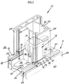
- the connection shown in Fig.1 shows an end a hollow profile rod 10, which is at right angles to the hollow profile rod 11 butts and with this via a connector 12 is connected.
- Both hollow section bars 10, 11 have rollovers 20, 20 'which face the outside of the room 26.
- the inside of the room 27 the smooth inner walls 28, 28 'are turned.
- the hollow profile rod has between the flap 20 and the inner wall 28 11 a longitudinal wall 11 '' with a glass retaining strip attachment 25 is provided.
- the glass retaining strip attachment is used to attach a glass retaining strip with the the glass of a window pane in the hollow profile bars 10, 11 formed frame is held.
- the glass retaining strip attachment 25 an undercut 24 with which Glass blocks on the frame or on the hollow profile rod 10, 11 fixed can be used to block the glass pane.
- a connector 12 is on the longitudinal wall 11 '' of the hollow section bar 11 attached and has an underside 12 ', the profiling the profiling of the hollow profile rod 11 in the area the longitudinal wall 11 '' must be adapted.
- the exact profiling can be seen from Figure 5, in which the connector 12 in a cross section is shown.
- the connector 12 To attach the connector 12 to the hollow profile rod 11, it is provided with two aligned footwraps 29, which the Longitudinal wall 11 '' are profiled accordingly and mounting holes 30, with which the connector 12 on the hollow profile rod 11 can be screwed.
- To connect the Connector 12 with the hollow profile rod 10 is one of the Longitudinal wall 11 ′′ vertically projecting engagement pin 31 available, which corresponds to the cavity 32 of the hollow profile rod 10 is profiled and engages in a form-fitting manner. The engagement takes place from the end face 13 of the hollow profile rod 10.
- sealing strips 14 are used. These consist of soft material that is used when attaching the connector 12 on the hollow profile bars 10, 11 is compressed and as a result seals. A specialty of the sealing strips 14 is their arrangement on the connector 12. This points Holding grooves 15 in which the sealing strips 14 are introduced are. All sealing strips are advantageous housed in retaining grooves 15.
- the sealing of the connector 12 against the hollow profile bars 10.11 is done on the top, which is the hollow section bar 10 is facing, and on the underside, that of the longitudinal wall 11 '' or the hollow profile rod 11 is turned.
- the arrangement of the sealing strips 14 on the top of the connector 12 is not only made so that all interior side of the rollover 20 of the hollow profile rod 11 abutting edges of the hollow section bar 10 with Sealing ribs 16 are sealed. Also in the area of A complete seal is achieved at rollover 20. Therefor is a sealing plate on the roll-over pin wall 31 ' 38 arranged, according to Fig.3,5,6 with the sealing strip 14 the top of the connector 12 in connection stands. On the upper edge 38 'of this sealing plate 38 is a sealing strip 14 with a sealing rib 16 provided that located on the associated butt edge 19 of the Rollover 20 'supports. As a result, the ingress of moisture from an outside space between the rollovers 20.20 'to the inside 27, excluded.
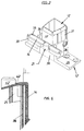
- Fig.2 shows a connector 12 which one between the Rollover 20 'and the rollover 20 arranged support web 39 has.
- This support web 39 is on the top with the previous described sealing strip 14 against the hollow profile rod 10 sealed.
- FIG. 6 shows a representation similar to that of FIG non-connector supported sealing.
- a sealing tab 42 is attached, which is about the outer contour of the sealing strip shown in Figure 2 14 has. It is also provided with knobs 42 ' engage in the cavities of the rollover 20 '. Both that connector-supported sealing strip 14, as well as the Sealing flap 42 is peculiar that they are each on sealing strips 14 of the connector 12.
- Fig. 6 shows one vertical sealing strips 14. In Figure 3 there are two of these vertical sealing strip 14 in supervision between one Fastening tab 34 and a wall of the pin 31 are arranged. In Figure 6 it is also shown that the sealing tab 42 is also in one piece with a sealing plate 38 which seals the space between the flap 20 and the pin 31 and is fixed to the pin.
- FIG 2 is further within a graphic Breakout shown that the connector 12 has a sealing projection 21, which according to Figure 5 below the support web 39 is formed. He reaches into a not shown Routing of the rollover 20. The routing extends pin parallel in the flap 20 so far that the seal mounting groove 22 is completely covered. This groove 22, the establishment of a seal for sealing on a Glass pane would serve as a free continuous channel form, if not the sealing projection 21 in the pin parallel Milling would be introduced and thus the free Passage of the groove 22 closes. Also others around in longitudinal grooves on the inside wall can with a correspondingly long sealing projection 21st be closed.
- the sealing projection 21 is made also made of elastic material and is with the sealing plate 38 one-piece.
- retaining grooves 15 For fastening the sealing plate 38 and the sealing projection 21 are also retaining grooves 15 provided in connector 12. It can be seen from Fig. 4 that all retaining grooves 15 for sealing strips 14 u. The like. Undercuts 17 can have around the sealing material to hold on connector 12.
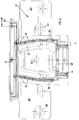
- the underside of the connector 12 is also with sealing means Mistake. 4 shows sealing strips 14, which each have double sealing ribs 16. Such sealing strips 14 are a mounting hole on both sides 40 available with which the connector 12 when used a fastening screw against the longitudinal wall 11 '' becomes. The sealing ribs 16 of the sealing strips 14 pressed against the longitudinal wall 11 ''. Another Sealing also takes place below the support tab 35 Has sealing strip 14 on both sides of locking pin 41, which engage in a groove of the glass retaining strip attachment 25. So that a tightness between the area of Underside of the support tab 35 and the underside of the connector 12 is reached, is a sealing nipple 23 is present, the cross section of the undercut 24 the glass retaining strip attachment 25 completely seals. Of the Sealing nipple 23 is with the sealing strip on the underside 14 of the support tab 35 in one piece, as with the plate-like sealing strip 14 of the connector 12 in the area of the mounting hole 40.
- the sealing means and in particular the sealing strip 14 has already been pointed out that these can be accommodated in retaining grooves 15 and with Protruding sealing ribs 16 from the retaining grooves 15. Consequently the sealing ribs 16 can be made narrower, than the areas in the retaining grooves 15 of FIG Sealing strip 14. This causes one for sealing sufficient compression of the protruding sealing ribs 16 already with low forces, because the ones below this sealing ribs located sealing strip 14 deformable are. Low mechanical forces can cause that the narrow sealing ribs 16 completely into the retaining grooves 15 are pressed in and it becomes a rigid support of the connector 12 comes on the hollow profile bars 10, 11.
- Figures 7, 8 show further improvements in the seal through special arrangement of sealing ribs 16.
- the underside 12 'of the connector 12 has 29 in the area of the foot flaps Sealing ribs 16 that surround the mounting holes 30. Moisture penetrating through the fastening holes 30, for example can not be distributed further.
- the mounting hole 40 of the connector 12 is surrounded by sealing ribs 16, namely from parallel arranged in parallel. Similar thing applies to the locking pins 41 surrounded by sealing ribs 16, for which, however, a seal inside the room was dispensed with by a sealing rib. In all cases is to ensure that the compression forces are sufficient stay low.
- the pin 31 is special provided with a chamber 42 facing the second profile bar, which is filled with elastic material.
- This elastic Material carries the double sealing ribs shown in Fig. 8 16. According to Figure 7 surrounds the elastic material the mounting hole 40 of the pin 31. In addition 7 shows how a non-connector-supported seal similar to Figure 6 with a sealing projection 21 in a recess of the flap 20 of the second hollow section bar 11 engages by a reinforcing profile 43 against Torsion is stiffened.
Landscapes
- Engineering & Computer Science (AREA)
- Civil Engineering (AREA)
- Structural Engineering (AREA)
- Mutual Connection Of Rods And Tubes (AREA)
- Joining Of Corner Units Of Frames Or Wings (AREA)
- Securing Of Glass Panes Or The Like (AREA)
- Lining Or Joining Of Plastics Or The Like (AREA)
- Joining Of Building Structures In Genera (AREA)
Abstract
Description
- Fig.1
- eine perspektivische Darstellung einer kompletten Verbindung zweier Hohlprofilstäbe mit einem Verbinder,
- Fig.2
- eine perspektivische Darstellung eines Verbinders ohne Hohlprofilstäbe,
- Fig.3
- eine Draufsicht auf einen Verbinder,
- Fig.4
- eine Untersicht eines Verbinders,
- Fig.5
- den Schnitt B-B des Verbinders der Fig.3,
- Fig.6
- eine der Fig.5 ähnliche Darstellung mit anderer Ausgestaltung der Abdichtung,
- Fig.7
- einen Schnitt durch einen Zapfen eines Verbinders, und
- Fig.8
- eine der Fig.4 ähnliche Unteransicht eines weiteren Verbinders.
Claims (17)
- Verbindung für winklig aneinanderstoßende Hohlprofilstäbe (10,11), insbesondere für Tür- oder Fensterrahmen, mit einem Verbinder (12), der in eine Stirnseite (13) eines ersten Hohlprofilstabs (10) eingesetzt und an einer Längswand (11'') eines zweiten Hohlprofilstabs (11) befestigt ist, und mit elastischen Abdichtungsstreifen (14), die am Verbinder (12) hohlprofilstabseitig und in Halterillen (15) des Verbinders (12) angeordnet sind und aus den Rillen (15) vorspringende Dichtungsrippen (16) aufweisen, dadurch gekennzeichnet, daß Stoßkanten (19) der Stirnseite (13) des ersten Hohlprofilstabs (10) an Dichtungsrippen (16) abgedichtet sind.
- Verbindung nach Anspruch 1, dadurch gekennzeichnet, daß die Abdichtungsstreifen (14) in Hinterschneidungen (17) der Halterillen (15) verankert sind.
- Verbindung nach Anspruch 1 oder 2, dadurch gekennzeichnet, daß die Abdichtungsstreifen (14) in zu den Halterillen (15) zusätzlichen Vertiefungen (18) verankert sind.
- Verbindung nach Anspruch 3, dadurch gekennzeichnet, daß sich die zusätzlichen Vertiefungen (18) über die an der Verankerungsstelle (18'') vorhandene gesamte Wandstärke des Verbinders (12) erstrecken.
- Verbindung nach einem der Ansprüche 1 bis 4, dadurch gekennzeichnet, daß die Abdichtungsstreifen (14) durch eine benachbarte Wand des Verbinders (12) hindurch mit einem anderen Abdichtungsstreifen (14) einstückig verbunden sind, bedarfsweise außerhalb des Bereichs von Halterillen (15).
- Verbindung nach einem der Ansprüche 1 bis 5, dadurch gekennzeichnet, daß Dichtungsrippen (16) aufweisende Abdichtungsstreifen (14) mit benachbarten Außenflächen des Verbinders (12) gleichliegen.
- Verbindung nach einem der Ansprüche 1 bis 6, dadurch gekennzeichnet, daß der Verbinder (12) eine auf den zweiten Profilstab (11) aufgesetzte Fußplatte aus Fußlappen (29) hat, die einen in den ersten Profilstab (10) eingesetzten Zapfen (31) aufweist, und daß der Außenumfang der Fußplatte in der Nähe des Zapfens (31) von zusammenhängenden Abdichtungsstreifen (14) praktisch komplett umhüllt ist.
- Verbindung nach einem der Ansprüche 1 bis 7, dadurch gekennzeichnet, daß der Zapfen (31) eine dem zweiten Verbinder (12) zugewandte offene Kammer (42) hat, die mit Dichtungsrippen (16) bildendem elastischem Material gefüllt ist.
- Verbindung nach einem der Ansprüche 1 bis 8, dadurch gekennzeichnet, daß Befestigungslöcher (30) eines Fußlappens (29) und/oder eine Befestigungsbohrung (40) des Verbinders (12) und/oder dessen Rastzapfen (41) anschlußseitig von Dichtungsrippen (16) umgeben sind.
- Verbindung nach einem der Ansprüche 1 bis 9, dadurch gekennzeichnet, daß die Abdichtungsstreifen (14) die Längswand (11'') des zweiten Hohlprofilstabs (11) quer komplett mit Dichtungsrippen (16) abdichten.
- Verbindung nach einem der Ansprüche 1 bis 10, dadurch gekennzeichnet, daß die die Dichtungsrippen (16) hohlprofilseitig aufweisenden Abdichtungsstreifen (14) in Halterillen (15) vorhanden sind, die sich in der Unterseite (12') des Verbinders (12) befinden.
- Verbindung nach einem der Ansprüche 1 bis 11, dadurch gekennzeichnet, daß die Stoßkanten (19) eines Überschlags (20) des zweiten Hohlprofilstabs (11) mit einem verbindergestützten Abdichtungsstreifen (14) oder mit einem zwischen den Überschlägen der beiden Hohlprofilstäbe (10,11) ungestützt einklemmbaren Dichtungslappen (42) abgedichtet sind, der jeweils an Abdichtungsstreifen (14) am Verbinder (12) und/oder an einer zapfenwandseitigen Abdichtungsplatte (38) des Verbinders (12) ansetzt.
- Verbindung nach einem der Ansprüche 1 bis 11, dadurch gekennzeichnet, daß sämtliche innenraumseitig eines Überschlags (20) des zweiten Hohlprofilstabs (11) gelegene Stoßkanten (19) der Stirnseite (13) des ersten Hohlprofilstabs (10) mit Dichtungsrippen (16) abgedichtet sind.
- Verbindung nach einem der Ansprüche 1 bis 13, dadurch gekennzeichnet, daß ein Abdichtungsvorsprung (21) vorhanden ist, der den Querschnitt einer Dichtungsbefestigungsnut (22) eines Überschlags (20) des zweiten Hohlprofilstabs (11) vollständig abdichtet.
- Verbindung nach einem der Ansprüche 1 bis 14, dadurch gekennzeichnet, daß ein Abdichtungsnippel (23) vorhanden ist, der den Querschnitt einer Hinterschneidung (24) einer Glashalteleistenbefestigung (25) des zweiten Hohlprofilstabs (11) vollständig abdichtet.
- Verbindung nach einem der Ansprüche 1 bis 15, dadurch gekennzeichnet, daß die Abdichtungsstreifen (14) miteinander und bedarfsweise mit weiteren Abdichtungsmitteln (z.B. Abdichtungsvorsprung (21)) einstückig ausgebildet sind.
- Verbindung nach einem der Ansprüche 1 bis 16, dadurch gekennzeichnet, daß den Dichtungsrippen (16) bei plattenartiger Ausbildung der Abdichtungsstreifen (14) rillenartige Vertiefungen benachbart sind.
Applications Claiming Priority (2)
| Application Number | Priority Date | Filing Date | Title |
|---|---|---|---|
| DE29620153U | 1996-11-20 | ||
| DE29620153U DE29620153U1 (de) | 1996-11-20 | 1996-11-20 | Verbindung für winklig aneinanderstoßende Hohlprofilstäbe |
Publications (2)
| Publication Number | Publication Date |
|---|---|
| EP0844358A1 true EP0844358A1 (de) | 1998-05-27 |
| EP0844358B1 EP0844358B1 (de) | 2004-08-11 |
Family
ID=8032194
Family Applications (1)
| Application Number | Title | Priority Date | Filing Date |
|---|---|---|---|
| EP97120043A Expired - Lifetime EP0844358B1 (de) | 1996-11-20 | 1997-11-15 | Verbindungselement für winklig aneinanderstossende Hohlprofilstäbe |
Country Status (4)
| Country | Link |
|---|---|
| EP (1) | EP0844358B1 (de) |
| AT (1) | ATE273436T1 (de) |
| DE (2) | DE29620153U1 (de) |
| PL (1) | PL184538B1 (de) |
Cited By (4)
| Publication number | Priority date | Publication date | Assignee | Title |
|---|---|---|---|---|
| DE10229272A1 (de) * | 2002-06-28 | 2004-02-12 | Eduard Hueck Gmbh & Co Kg | Stoßverbinder zum winkeligen Verbinden von Hohlprofilen |
| DE102007053525A1 (de) * | 2007-11-09 | 2009-06-10 | Inoutic / Deceuninck Gmbh | Schwellenverbinder |
| GB2456513A (en) * | 2008-01-15 | 2009-07-22 | Hadley Ind Holdings Ltd | Door frame connector |
| WO2025051882A1 (de) * | 2023-09-07 | 2025-03-13 | Maco Technologie Gmbh | Bodenschwelle |
Families Citing this family (6)
| Publication number | Priority date | Publication date | Assignee | Title |
|---|---|---|---|---|
| DE19828382C2 (de) * | 1998-06-25 | 2003-03-27 | Reichel Phi Gmbh | Anordnung zum Befestigen eines einen Hohlquerschnitt aufweisenden Pfostens am Blendrahmen eines Fensters oder einer Türe aus Kunststoff oder Leichtmetall |
| DE10012762C1 (de) * | 2000-03-16 | 2001-11-29 | Reichel Phi Gmbh | Querverbinder |
| DE10016090A1 (de) * | 2000-03-31 | 2001-10-11 | Laeken Fensterzubehoer Gmbh | Kämpferverbinder |
| DE102007002605A1 (de) * | 2007-01-12 | 2008-07-17 | Eduard Hueck Gmbh & Co Kg | Stoßverbinder sowie Profilanordnung mit einem Stoßverbinder |
| DE202007015356U1 (de) * | 2007-11-02 | 2009-03-19 | Rehau Ag + Co | Mechanischer Verbinder |
| DE202008003931U1 (de) * | 2008-03-20 | 2009-07-30 | Rehau Ag + Co | Endkappe |
Citations (8)
| Publication number | Priority date | Publication date | Assignee | Title |
|---|---|---|---|---|
| FR2561301A1 (fr) * | 1984-03-13 | 1985-09-20 | Conforglace Sa | Nouvelle piece d'assemblage entre profiles extrudes principal et intermediaire pour chassis de fenetre et chassis de fenetre a profiles ainsi assembles |
| EP0569986A1 (de) * | 1992-05-15 | 1993-11-18 | Hans-Dieter Niemann | Verbindung für winklig aneinanderstossende Hohlprofilstäbe |
| DE9406655U1 (de) * | 1994-04-21 | 1994-06-30 | MFT GmbH - Moderne Fenster Technik -, 26871 Papenburg | Verbindungsstück für winklig aneinanderstoßende Hohlprofilstäbe |
| DE4320284A1 (de) * | 1993-06-18 | 1994-12-22 | Sfs Ind Holding Ag | Dichtungsanordnung für den Einsatz bei mechanisch miteinander zu verbindenden Pfosten- und Rahmenelementen |
| DE9316308U1 (de) * | 1993-10-27 | 1995-02-23 | Niemann, Hans Dieter, 50169 Kerpen | Verbindungsstück für winklig aneinanderstoßende Rahmenstäbe |
| DE4444274A1 (de) * | 1994-01-26 | 1995-08-03 | Hans Dieter Grotefeld | Kämpfer-Verbinder |
| DE29513516U1 (de) * | 1995-08-23 | 1995-10-19 | MFT - Moderne Fenster Technik - GmbH, 26871 Papenburg | Verbindungs- und Abdichtstück für stumpf aneinanderstoßende Hohlprofilstäbe für Fenster- und Türrahmen |
| DE29606446U1 (de) * | 1996-04-09 | 1996-07-18 | Rehau Ag + Co, 95111 Rehau | Verbinder zur mechanischen Verbindung von Hohlkammerprofilen |
Family Cites Families (8)
| Publication number | Priority date | Publication date | Assignee | Title |
|---|---|---|---|---|
| US2918708A (en) * | 1958-07-17 | 1959-12-29 | Arcadia Metal Products | Corner joint structure |
| CH587977A5 (de) * | 1975-06-16 | 1977-05-31 | Alusuisse | |
| EP0294170A1 (de) * | 1987-06-02 | 1988-12-07 | National Profiles Limited | Demontierbare Eckverbindung für einen Paneelrahmen und Elementensatz für seine Herstellung |
| DE8916130U1 (de) * | 1989-11-23 | 1994-03-10 | Schüco International KG, 33609 Bielefeld | T-Verbindung zwischen zwei Profilen, vorzugsweise einem Sprossen- und einem Pfostenprofil einer Fassade |
| GB9222836D0 (en) * | 1992-10-30 | 1992-12-09 | Indigo Products Limited | Improvements in or relating to joints for connecting together hollow frame members |
| DE4306420A1 (de) * | 1993-03-02 | 1994-09-08 | Schueco Int Kg | T-Verbindung zwischen zwei Profilen |
| DE9405126U1 (de) * | 1994-03-25 | 1994-05-19 | Grotefeld, Hans Dieter, 32549 Bad Oeynhausen | Kämpfer-Verbinder |
| DE9415129U1 (de) * | 1994-09-17 | 1994-11-03 | GEWE SELECTA Fenster- und Rolladenfabrik Heinrich Weihe GmbH & Co. KG, 32425 Minden | Verbindungsvorrichtung für Hohlprofilstreben von Fenstern, Türen o.dgl. |
-
1996
- 1996-11-20 DE DE29620153U patent/DE29620153U1/de not_active Expired - Lifetime
-
1997
- 1997-11-15 DE DE59711846T patent/DE59711846D1/de not_active Expired - Lifetime
- 1997-11-15 AT AT97120043T patent/ATE273436T1/de active
- 1997-11-15 EP EP97120043A patent/EP0844358B1/de not_active Expired - Lifetime
- 1997-11-19 PL PL97323224A patent/PL184538B1/pl not_active IP Right Cessation
Patent Citations (8)
| Publication number | Priority date | Publication date | Assignee | Title |
|---|---|---|---|---|
| FR2561301A1 (fr) * | 1984-03-13 | 1985-09-20 | Conforglace Sa | Nouvelle piece d'assemblage entre profiles extrudes principal et intermediaire pour chassis de fenetre et chassis de fenetre a profiles ainsi assembles |
| EP0569986A1 (de) * | 1992-05-15 | 1993-11-18 | Hans-Dieter Niemann | Verbindung für winklig aneinanderstossende Hohlprofilstäbe |
| DE4320284A1 (de) * | 1993-06-18 | 1994-12-22 | Sfs Ind Holding Ag | Dichtungsanordnung für den Einsatz bei mechanisch miteinander zu verbindenden Pfosten- und Rahmenelementen |
| DE9316308U1 (de) * | 1993-10-27 | 1995-02-23 | Niemann, Hans Dieter, 50169 Kerpen | Verbindungsstück für winklig aneinanderstoßende Rahmenstäbe |
| DE4444274A1 (de) * | 1994-01-26 | 1995-08-03 | Hans Dieter Grotefeld | Kämpfer-Verbinder |
| DE9406655U1 (de) * | 1994-04-21 | 1994-06-30 | MFT GmbH - Moderne Fenster Technik -, 26871 Papenburg | Verbindungsstück für winklig aneinanderstoßende Hohlprofilstäbe |
| DE29513516U1 (de) * | 1995-08-23 | 1995-10-19 | MFT - Moderne Fenster Technik - GmbH, 26871 Papenburg | Verbindungs- und Abdichtstück für stumpf aneinanderstoßende Hohlprofilstäbe für Fenster- und Türrahmen |
| DE29606446U1 (de) * | 1996-04-09 | 1996-07-18 | Rehau Ag + Co, 95111 Rehau | Verbinder zur mechanischen Verbindung von Hohlkammerprofilen |
Cited By (4)
| Publication number | Priority date | Publication date | Assignee | Title |
|---|---|---|---|---|
| DE10229272A1 (de) * | 2002-06-28 | 2004-02-12 | Eduard Hueck Gmbh & Co Kg | Stoßverbinder zum winkeligen Verbinden von Hohlprofilen |
| DE102007053525A1 (de) * | 2007-11-09 | 2009-06-10 | Inoutic / Deceuninck Gmbh | Schwellenverbinder |
| GB2456513A (en) * | 2008-01-15 | 2009-07-22 | Hadley Ind Holdings Ltd | Door frame connector |
| WO2025051882A1 (de) * | 2023-09-07 | 2025-03-13 | Maco Technologie Gmbh | Bodenschwelle |
Also Published As
| Publication number | Publication date |
|---|---|
| DE59711846D1 (de) | 2004-09-16 |
| PL323224A1 (en) | 1998-05-25 |
| ATE273436T1 (de) | 2004-08-15 |
| DE29620153U1 (de) | 1998-03-19 |
| EP0844358B1 (de) | 2004-08-11 |
| PL184538B1 (pl) | 2002-11-29 |
Similar Documents
| Publication | Publication Date | Title |
|---|---|---|
| EP1020575B1 (de) | T-Verbindung zwischen einem Sprossen- und einem Pfostenprofil einer Fasade oder eines Lichtdaches | |
| EP0185222B1 (de) | Abstandhaltender Rahmen für eine Isolierverglasung | |
| EP0843062B1 (de) | Halteelement für Fensterbeschlag | |
| EP0100991A2 (de) | Verbundprofil | |
| EP0616107A1 (de) | Stossverbindung | |
| EP0114222B1 (de) | Aus Hohlprofilen, vorzugsweise wärmegedämmten Verbundprofilen, hergestellter Tür- oder Fensterrahmen mit mindestens einer Sprosse | |
| EP1026357B1 (de) | Rahmenprofil für Holz-Metall-Fenster oder -Türen | |
| EP0844358B1 (de) | Verbindungselement für winklig aneinanderstossende Hohlprofilstäbe | |
| EP0179241A2 (de) | Plattenförmiges Bauelement | |
| DE4442074C2 (de) | Pfosten-, Sprossen- und Kreuzverbinder | |
| EP0651125A1 (de) | Verbindungsstück für winklig aneinanderstossende Rahmenstäbe | |
| EP0801202B1 (de) | Verbindungsvorrichtung für eine Sprossenkreuzkonstuktion | |
| DE19828382C2 (de) | Anordnung zum Befestigen eines einen Hohlquerschnitt aufweisenden Pfostens am Blendrahmen eines Fensters oder einer Türe aus Kunststoff oder Leichtmetall | |
| DE2130023C2 (de) | Kunststoffrahmen für Fenster, Türen od.dgl. | |
| EP0634557A2 (de) | Türzarge mit einer Brandschutzleiste | |
| DE2627920A1 (de) | Eckverbindungswinkel fuer abstandshalteprofile eines mehrscheibenisolierglases | |
| DE3516141C2 (de) | ||
| EP0110295A2 (de) | Abstandhalterrahmen für randverklebte Isolierglasscheiben | |
| DE9305040U1 (de) | Mittel zum Abdichten einer Verbindung zwischen Rahmen für Fenster, Türen o.dgl. mit einem Pfosten | |
| DE19756899C2 (de) | Verfahren zur Montage von Scheiben und vorgefertigte Rahmenleiste zur Ausbildung eines geschlossenen Rahmens für Fensterscheiben | |
| DE10006962A1 (de) | Eckwinkel mit Endabdichtung | |
| DE29609162U1 (de) | Strangförmige Dichtung | |
| EP1398452B1 (de) | Rahmenhohlprofile aus Kunststoff oder Metall | |
| DE19634987A1 (de) | Verfahren zum Zusammenbauen von Isolierglasscheiben mit thermoplastischen Abstandhalter und mit eingesetztem Sprossenrahmen | |
| DE1198521B (de) | Fenster bzw. Tuer, dessen bzw. deren feststehender Zargenrahmen und beweglicher Fluegelrahmen je aus einem Holz- und einem Metall- oder Kunststoffrahmen bestehen |
Legal Events
| Date | Code | Title | Description |
|---|---|---|---|
| PUAI | Public reference made under article 153(3) epc to a published international application that has entered the european phase |
Free format text: ORIGINAL CODE: 0009012 |
|
| AK | Designated contracting states |
Kind code of ref document: A1 Designated state(s): AT BE CH DE DK ES FR GB LI NL |
|
| AX | Request for extension of the european patent |
Free format text: AL;LT;LV;MK;RO;SI |
|
| 17P | Request for examination filed |
Effective date: 19980829 |
|
| AKX | Designation fees paid |
Free format text: AT BE CH DE DK ES FR GB LI NL |
|
| RBV | Designated contracting states (corrected) |
Designated state(s): AT BE CH DE DK ES FR GB LI NL |
|
| 17Q | First examination report despatched |
Effective date: 20030508 |
|
| GRAP | Despatch of communication of intention to grant a patent |
Free format text: ORIGINAL CODE: EPIDOSNIGR1 |
|
| RTI1 | Title (correction) |
Free format text: CONNECTION ELEMENT FOR HOLLOW PROFILE MEMBERS MEETING AT AN ANGLE |
|
| GRAS | Grant fee paid |
Free format text: ORIGINAL CODE: EPIDOSNIGR3 |
|
| GRAA | (expected) grant |
Free format text: ORIGINAL CODE: 0009210 |
|
| AK | Designated contracting states |
Kind code of ref document: B1 Designated state(s): AT BE CH DE DK ES FR GB LI NL |
|
| PG25 | Lapsed in a contracting state [announced via postgrant information from national office to epo] |
Ref country code: GB Free format text: LAPSE BECAUSE OF FAILURE TO SUBMIT A TRANSLATION OF THE DESCRIPTION OR TO PAY THE FEE WITHIN THE PRESCRIBED TIME-LIMIT Effective date: 20040811 |
|
| REG | Reference to a national code |
Ref country code: GB Ref legal event code: FG4D Free format text: NOT ENGLISH |
|
| RIN1 | Information on inventor provided before grant (corrected) |
Inventor name: NIEMANN, HANS DIETER Inventor name: AHRENS, MAIK Inventor name: WITTE, MANUELA |
|
| REG | Reference to a national code |
Ref country code: CH Ref legal event code: EP |
|
| REF | Corresponds to: |
Ref document number: 59711846 Country of ref document: DE Date of ref document: 20040916 Kind code of ref document: P |
|
| PG25 | Lapsed in a contracting state [announced via postgrant information from national office to epo] |
Ref country code: DK Free format text: LAPSE BECAUSE OF FAILURE TO SUBMIT A TRANSLATION OF THE DESCRIPTION OR TO PAY THE FEE WITHIN THE PRESCRIBED TIME-LIMIT Effective date: 20041111 |
|
| PG25 | Lapsed in a contracting state [announced via postgrant information from national office to epo] |
Ref country code: ES Free format text: LAPSE BECAUSE OF FAILURE TO SUBMIT A TRANSLATION OF THE DESCRIPTION OR TO PAY THE FEE WITHIN THE PRESCRIBED TIME-LIMIT Effective date: 20041122 |
|
| PG25 | Lapsed in a contracting state [announced via postgrant information from national office to epo] |
Ref country code: LI Free format text: LAPSE BECAUSE OF NON-PAYMENT OF DUE FEES Effective date: 20041130 Ref country code: CH Free format text: LAPSE BECAUSE OF NON-PAYMENT OF DUE FEES Effective date: 20041130 Ref country code: BE Free format text: LAPSE BECAUSE OF NON-PAYMENT OF DUE FEES Effective date: 20041130 |
|
| GBV | Gb: ep patent (uk) treated as always having been void in accordance with gb section 77(7)/1977 [no translation filed] |
Effective date: 20040811 |
|
| BERE | Be: lapsed |
Owner name: NIEMANN, HANS DIETER Effective date: 20041130 |
|
| PLBE | No opposition filed within time limit |
Free format text: ORIGINAL CODE: 0009261 |
|
| STAA | Information on the status of an ep patent application or granted ep patent |
Free format text: STATUS: NO OPPOSITION FILED WITHIN TIME LIMIT |
|
| ET | Fr: translation filed | ||
| REG | Reference to a national code |
Ref country code: CH Ref legal event code: PL |
|
| 26N | No opposition filed |
Effective date: 20050512 |
|
| BERE | Be: lapsed |
Owner name: *NIEMANN HANS DIETER Effective date: 20041130 |
|
| PGFP | Annual fee paid to national office [announced via postgrant information from national office to epo] |
Ref country code: NL Payment date: 20101111 Year of fee payment: 14 Ref country code: FR Payment date: 20101130 Year of fee payment: 14 Ref country code: AT Payment date: 20101112 Year of fee payment: 14 |
|
| PGFP | Annual fee paid to national office [announced via postgrant information from national office to epo] |
Ref country code: DE Payment date: 20101229 Year of fee payment: 14 |
|
| REG | Reference to a national code |
Ref country code: DE Ref legal event code: R082 Ref document number: 59711846 Country of ref document: DE Representative=s name: DRAUDT, AXEL, DIPL.-ING., DE Effective date: 20110705 Ref country code: DE Ref legal event code: R082 Ref document number: 59711846 Country of ref document: DE Representative=s name: AXEL DRAUDT, DE Effective date: 20110705 Ref country code: DE Ref legal event code: R081 Ref document number: 59711846 Country of ref document: DE Owner name: ROTO GLUSKE-BKV GMBH, DE Free format text: FORMER OWNER: NIEMANN, HANS DIETER, 50169 KERPEN, DE Effective date: 20110705 Ref country code: DE Ref legal event code: R081 Ref document number: 59711846 Country of ref document: DE Owner name: ROTO GLUSKE-BKV GMBH, DE Free format text: FORMER OWNER: HANS DIETER NIEMANN, 50169 KERPEN, DE Effective date: 20110705 |
|
| REG | Reference to a national code |
Ref country code: NL Ref legal event code: V1 Effective date: 20120601 |
|
| PG25 | Lapsed in a contracting state [announced via postgrant information from national office to epo] |
Ref country code: NL Free format text: LAPSE BECAUSE OF NON-PAYMENT OF DUE FEES Effective date: 20120601 |
|
| REG | Reference to a national code |
Ref country code: FR Ref legal event code: ST Effective date: 20120731 |
|
| REG | Reference to a national code |
Ref country code: DE Ref legal event code: R119 Ref document number: 59711846 Country of ref document: DE Effective date: 20120601 |
|
| REG | Reference to a national code |
Ref country code: AT Ref legal event code: MM01 Ref document number: 273436 Country of ref document: AT Kind code of ref document: T Effective date: 20111115 |
|
| PG25 | Lapsed in a contracting state [announced via postgrant information from national office to epo] |
Ref country code: FR Free format text: LAPSE BECAUSE OF NON-PAYMENT OF DUE FEES Effective date: 20111130 |
|
| PG25 | Lapsed in a contracting state [announced via postgrant information from national office to epo] |
Ref country code: AT Free format text: LAPSE BECAUSE OF NON-PAYMENT OF DUE FEES Effective date: 20111115 |
|
| PG25 | Lapsed in a contracting state [announced via postgrant information from national office to epo] |
Ref country code: DE Free format text: LAPSE BECAUSE OF NON-PAYMENT OF DUE FEES Effective date: 20120601 |