EP0844504A2 - Boíte de connexion pour des cables optiques - Google Patents
Boíte de connexion pour des cables optiques Download PDFInfo
- Publication number
- EP0844504A2 EP0844504A2 EP97119046A EP97119046A EP0844504A2 EP 0844504 A2 EP0844504 A2 EP 0844504A2 EP 97119046 A EP97119046 A EP 97119046A EP 97119046 A EP97119046 A EP 97119046A EP 0844504 A2 EP0844504 A2 EP 0844504A2
- Authority
- EP
- European Patent Office
- Prior art keywords
- connection unit
- cable
- unit according
- base part
- plugs
- Prior art date
- Legal status (The legal status is an assumption and is not a legal conclusion. Google has not performed a legal analysis and makes no representation as to the accuracy of the status listed.)
- Granted
Links
Images


Classifications
-
- G—PHYSICS
- G02—OPTICS
- G02B—OPTICAL ELEMENTS, SYSTEMS OR APPARATUS
- G02B6/00—Light guides; Structural details of arrangements comprising light guides and other optical elements, e.g. couplings
- G02B6/46—Processes or apparatus adapted for installing or repairing optical fibres or optical cables
- G02B6/47—Installation in buildings
- G02B6/475—Mechanical aspects of installing cables in ducts or the like for buildings
-
- G—PHYSICS
- G02—OPTICS
- G02B—OPTICAL ELEMENTS, SYSTEMS OR APPARATUS
- G02B6/00—Light guides; Structural details of arrangements comprising light guides and other optical elements, e.g. couplings
- G02B6/44—Mechanical structures for providing tensile strength and external protection for fibres, e.g. optical transmission cables
- G02B6/4439—Auxiliary devices
- G02B6/444—Systems or boxes with surplus lengths
- G02B6/44528—Patch-cords; Connector arrangements in the system or in the box
-
- G—PHYSICS
- G02—OPTICS
- G02B—OPTICAL ELEMENTS, SYSTEMS OR APPARATUS
- G02B6/00—Light guides; Structural details of arrangements comprising light guides and other optical elements, e.g. couplings
- G02B6/46—Processes or apparatus adapted for installing or repairing optical fibres or optical cables
- G02B6/47—Installation in buildings
- G02B6/477—Wall sockets
-
- G—PHYSICS
- G02—OPTICS
- G02B—OPTICAL ELEMENTS, SYSTEMS OR APPARATUS
- G02B6/00—Light guides; Structural details of arrangements comprising light guides and other optical elements, e.g. couplings
- G02B6/44—Mechanical structures for providing tensile strength and external protection for fibres, e.g. optical transmission cables
- G02B6/4439—Auxiliary devices
- G02B6/4459—Ducts; Conduits; Hollow tubes for air blown fibres
Definitions
- the invention relates to a connection unit for optical fiber cables.
- connection unit for fiber optic cables known, at an arrangement for storing splice cassettes for optical fibers is provided within a cable sleeve.
- a such an arrangement is used where optical fiber splices protected against moisture in a pressure-tight manner have to.
- this effort is not necessary when making connections on fiber optic systems within buildings should be made possible.
- the task arises, if possible simple connection unit for pluggable connection
- To create fiber optic systems that are universal is adapted to structural conditions and that with it a quick and uncomplicated coupling to under plaster, on Plaster, fiber optic cables laid in pipe or line ducts can be created.
- connection unit for fiber optic cables solved that a base part cable catchers on two End faces and in between in the middle of the base part, that a through opening in the base plate of the Base part is arranged, which is dimensioned so that with Plug-provided ends of fiber optic fibers can be carried out are that circular guide channels for filing for excess lengths of fiber optic fibers around the lead-through opening are trained around that the connectors of the fiber optic fibers in connector holders are fastened with fasteners that the connector brackets can be plugged in fixations that the connector slots assigned entries are provided, their closures if necessary for the connection of connectors Optical fiber fibers are removable and that one removable cover is placed over the base part.
- connection unit can be seen in the fact that they create connections on existing fiber optic systems inside buildings with the help of plug combinations in universal Type can be used. So it is suitable for the introduction and the connection of cables that are on plaster, under Plaster, in pipes or in conduits, alike Well; because the cable ends can be inserted from the side, from below as from the middle. Doing so each ensures that the fiber optic cables minimum permissible bending radii for fiber optic fibers not less than 30 mm. Also done the management of fiber optic excess lengths of the to be connected Optical fibers in a circular design Guide channels, so that here too an undercut of the permissible bending radius is not possible.
- the cable entries are also designed as cable interception devices and are arranged so that the storage of excess lengths of fiber optic fibers in two opposite Directions or turns can take place. That way it is possible that outputs of fiber optic fibers also in close to the cable entry can be provided without that there is a risk of kinking; because the feed is done by inserting the fiber optic excess lengths in a guide channel in the appropriate direction of insertion.
- the ends of the fiber optic fibers can already be pre-assembled with plugs, because in the There is a large lead-through opening in the middle of the connection unit, which is dimensioned so that the already with plugs provided fiber optic fiber ends are passed can.
- the same cable interception devices are always used used so that no additional measures are taken Need to become.
- connection unit the excess lengths in the Guide channels laid in the appropriate direction of insertion, appropriate hold-down devices ensure that the optical fibers not when opening the connection unit jump out.
- the connectors on the ends of the fiber optic fibers are held in connector brackets, which are then in Fixations inserted on the base part of the connection unit, preferably be snapped into place. That way ensured that the assembly with plugs
- the plug holders are removed from the connection unit can be, for example, a splicer feed.
- the connectors are with the connector brackets locked in the fixations so that supplied from the outside Plug connections can be used effortlessly, then the corresponding closures in the outlets of the Connection unit can be removed as required.
- the above The embodiment shows a design below, in connection options for four simplex connectors or are provided for two duplex plugs.
- connection unit according to the invention also directly on line channels or armament channels, so that no additional Measures must be taken. This direct You can also put it on with the appropriate mounting frame are provided, with the help of the connection unit is clamped onto the cover panel.
- connection unit consists of the base part 1, the connector holders 3 for receiving the at the ends of the optical fibers attached connector and the cover 2, which the Covered interior, with the insertion to be introduced through 13a Plugs from connecting cables can be inserted.
- the base part 1 consists of the base plate, which means different struts, ribs and the like is stiffened. There are also holes and locking devices and the like, by which in known per se Way universal mounting options are given.
- the cable entries are also used as cable interception devices 6 or 7, e.g.
- the two side cable support devices 6 are designed so that the introduction of fiber optic cables from below as well as at the same height, so that optical fiber cables can be introduced, the on plaster, under plaster or in pipes or channels are.
- a direct entry can be made in the central cable clamp 7 can be made.
- Through webs 8 or / and Pins 9 are formed guide channels 5, in which excess lengths of optical fibers can be stored, so that the ends of the optical fibers with plugs be provided or already are, from the base part 1 for Service purposes can be removed.
- the leadership channels 5 run around a large insertion opening 4 around, these being arranged approximately centrally in the base part 1 is.
- the diameter of the circular guide channels 5 is so large that a bending injury to the optical waveguide is excluded (minimum permissible bending diameter ⁇ 30 mm).
- the central cable entry 4 is with a Provide collar 15, on the same as on the edge of the base part 1 hold-down 35 are attached, which jump out prevent inserted fiber optic fibers.
- the collar 15 also has outlets 34 which also extend to the base plate and up to the respective cable interception device 6 can be broken out, so that the bottom inserted optical fiber cables are led upwards can.
- This cable entry opening 4 is so big and so shaped that fiber optic cables already provided with plugs or optical fibers are introduced can, the fiber optic cables to the Cable interception devices 6 are performed.
- the fiber ends of the inserted Optical fiber cables are or are provided with plugs, the now in shots 10 of removable connector holders 3 by means of fastening means 33, for example clamps or screws.
- By the label 12 within the cover 2 is the socket of the optical fibers outlined in a plug.
- the connector brackets 3 are in fixations 14, for example in groove guides, inserted so that they are there mechanically in their position are set.
- the closures 13b on Base part 1 removed, so that the plug of the outside to be connected and plugged in can be.
- the connector brackets 3 can each used plugs can be adapted and for example Recordings 10 for two or one plug included.
- the cable interception device 7 can be seen in the example an optical fiber cable laid on plaster in a known per se Way is introduced and intercepted.
- the cover panel 2 can be placed on the base part 1 and preferably be snapped on.
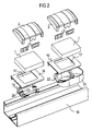
- FIG. 2 shows the assembly process of a connection unit according to of the invention on a conduit or parapet duct 18, in the fiber optic cable laid inside buildings will.
- the line duct 18 is covered in the Area in which a connection possibility is created should, with a cover 16, which on the conduit 18th is snapped on.
- This cover 16 is with a cutout 17 provided, through which the cable to be connected the conduit 18 out into the base part 1 of the connection unit is performed according to the invention.
- the attachment of the base part 1 is done either directly or with the help a mounting frame 19, which is below the cover 16 is arranged and with the help of fasteners 23 is clamped to the base part 1 to be fastened above.
- This embodiment is shown in the left part of Figure 2.
- the right part of this figure 2 shows that here the mounting frame as a container 21 with entries 22 is trained. Within this container 21 can now Excess lengths, splices and the like are stored. in the the rest of the composition is as in the already described embodiment of the left part of the figure.
- FIG. 3 shows the introduction of an optical waveguide cable 27 from below, which is intercepted in the cable interception device 28 becomes. It can be seen that this cable interception device 28 is aligned so that the optical fibers are too long 29 and 30 in opposite directions in one of the guide channel formed by the pins 9 out can be. In this way it is possible for fiber optic fibers to both side positions of the connector holders 3 while observing the minimum permissible bending radius can be guided for optical fibers. Farther can be seen that in the left connector holder 3 two individual connectors 24 and in the right connector holder 3 a double connector 11 are used to the externally guided connector 25 and 26 connected by fiber optic fibers 36 are. The connector holders 3 are also in fixations here 14 inserted, from which they are removed for service purposes can be.
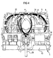
- Figure 4 finally shows the introduction of an optical fiber cable 29 in the centrally arranged cable interception device 7, from where the excess lengths are also laid 31 and 32 of the optical fibers in two directions within the guide channels can take place.
- Cable entries are initially completed by closures 13b are.
Landscapes
- Physics & Mathematics (AREA)
- Engineering & Computer Science (AREA)
- Civil Engineering (AREA)
- Structural Engineering (AREA)
- General Physics & Mathematics (AREA)
- Optics & Photonics (AREA)
- Light Guides In General And Applications Therefor (AREA)
- Mechanical Coupling Of Light Guides (AREA)
- Cable Accessories (AREA)
Applications Claiming Priority (2)
| Application Number | Priority Date | Filing Date | Title |
|---|---|---|---|
| DE19648294 | 1996-11-21 | ||
| DE19648294 | 1996-11-21 |
Publications (3)
| Publication Number | Publication Date |
|---|---|
| EP0844504A2 true EP0844504A2 (fr) | 1998-05-27 |
| EP0844504A3 EP0844504A3 (fr) | 1999-03-31 |
| EP0844504B1 EP0844504B1 (fr) | 2003-04-16 |
Family
ID=7812405
Family Applications (1)
| Application Number | Title | Priority Date | Filing Date |
|---|---|---|---|
| EP97119046A Expired - Lifetime EP0844504B1 (fr) | 1996-11-21 | 1997-10-31 | Boíte de connexion pour des cables optiques |
Country Status (4)
| Country | Link |
|---|---|
| EP (1) | EP0844504B1 (fr) |
| AT (1) | ATE237820T1 (fr) |
| DE (1) | DE59709848D1 (fr) |
| ES (1) | ES2196235T3 (fr) |
Cited By (22)
| Publication number | Priority date | Publication date | Assignee | Title |
|---|---|---|---|---|
| WO2005088373A1 (fr) * | 2004-03-08 | 2005-09-22 | Adc Telecommunications, Inc. | Terminal d'acces de fibre optique |
| US7333708B2 (en) | 2004-01-27 | 2008-02-19 | Corning Cable Systems Llc | Multi-port optical connection terminal |
| USRE40358E1 (en) | 1998-07-27 | 2008-06-03 | Adc Telecommunications, Inc. | Outside plant fiber distribution apparatus and method |
| FR2916284A1 (fr) * | 2007-05-14 | 2008-11-21 | Free Soc Par Actions Simplifie | Capot de protection de fibre optique |
| US7477824B2 (en) | 2006-04-05 | 2009-01-13 | Adc Telecommunications, Inc. | Universal bracket for mounting a drop terminal |
| US7489849B2 (en) | 2004-11-03 | 2009-02-10 | Adc Telecommunications, Inc. | Fiber drop terminal |
| US7512304B2 (en) | 2007-03-23 | 2009-03-31 | Adc Telecommunications, Inc. | Drop terminal with anchor block for retaining a stub cable |
| EP2045636A1 (fr) * | 2007-10-04 | 2009-04-08 | Nexans | Prise optique pour reseau de telecommunication |
| US7558458B2 (en) | 2007-03-08 | 2009-07-07 | Adc Telecommunications, Inc. | Universal bracket for mounting a drop terminal |
| US7680388B2 (en) | 2004-11-03 | 2010-03-16 | Adc Telecommunications, Inc. | Methods for configuring and testing fiber drop terminals |
| US7740409B2 (en) | 2007-09-19 | 2010-06-22 | Corning Cable Systems Llc | Multi-port optical connection terminal |
| US7844158B2 (en) | 2007-10-09 | 2010-11-30 | Adc Telecommunications, Inc. | Mini drop terminal |
| WO2011019574A1 (fr) * | 2009-08-13 | 2011-02-17 | Commscope, Inc. Of North Carolina | Composant de gestion de fibre |
| US7903923B2 (en) | 2007-10-09 | 2011-03-08 | Adc Telecommunications, Inc. | Drop terminal releasable engagement mechanism |
| EP2400330A1 (fr) * | 2010-06-22 | 2011-12-28 | CCS Technology, Inc. | Appareil pour la manipulation de guides d'ondes optiques |
| FR2979438A1 (fr) * | 2011-08-30 | 2013-03-01 | Legrand France | Dipositif de lovage, accessoire de lovage et dispositif de connexion pour fibre optique |
| US8755663B2 (en) | 2010-10-28 | 2014-06-17 | Corning Cable Systems Llc | Impact resistant fiber optic enclosures and related methods |
| US8873926B2 (en) | 2012-04-26 | 2014-10-28 | Corning Cable Systems Llc | Fiber optic enclosures employing clamping assemblies for strain relief of cables, and related assemblies and methods |
| US9069151B2 (en) | 2011-10-26 | 2015-06-30 | Corning Cable Systems Llc | Composite cable breakout assembly |
| CN101539650B (zh) * | 2004-03-08 | 2016-01-27 | Adc电信公司 | 光纤接入终端 |
| DE102016101333A1 (de) * | 2016-01-26 | 2017-07-27 | "Durable" Hunke & Jochheim Gmbh & Co. Kommanditgesellschaft | Kabelhalter, Kabelhaltersystem und Gerätehaltersystem |
| US11899262B2 (en) | 2019-03-29 | 2024-02-13 | Commscope Technologies Llc | Fiber management components for telelcommunications closures |
Family Cites Families (7)
| Publication number | Priority date | Publication date | Assignee | Title |
|---|---|---|---|---|
| US4976510B2 (en) * | 1989-11-20 | 1995-05-09 | Siecor Corp | Communication outlet |
| GB9027074D0 (en) * | 1990-12-13 | 1991-02-06 | Bicc Plc | Optical fibre termination device |
| US5109467A (en) * | 1991-02-27 | 1992-04-28 | Keptel, Inc. | Interconnect cabinet for optical fibers |
| JPH06508448A (ja) * | 1991-06-18 | 1994-09-22 | ブリテイッシュ・テレコミュニケーションズ・パブリック・リミテッド・カンパニー | 光ファイバー接続装置 |
| DE4218378C2 (de) * | 1992-06-04 | 1994-06-01 | Rose Walter Gmbh & Co Kg | Kabelanschlußkasten |
| DE9304131U1 (de) * | 1993-02-16 | 1993-05-13 | Walter Rose Gmbh & Co Kg, 5800 Hagen | Vorrichtung zum Aufteilen von Lichtwellenleiterkabeln und -adern |
| US5335304A (en) * | 1993-04-30 | 1994-08-02 | The United States Of America As Represented By The Secretary Of The Army | Connector distribution assembly for a fiber optic detector system |
-
1997
- 1997-10-31 DE DE59709848T patent/DE59709848D1/de not_active Expired - Lifetime
- 1997-10-31 EP EP97119046A patent/EP0844504B1/fr not_active Expired - Lifetime
- 1997-10-31 AT AT97119046T patent/ATE237820T1/de not_active IP Right Cessation
- 1997-10-31 ES ES97119046T patent/ES2196235T3/es not_active Expired - Lifetime
Cited By (50)
| Publication number | Priority date | Publication date | Assignee | Title |
|---|---|---|---|---|
| USRE42258E1 (en) | 1998-07-27 | 2011-03-29 | Adc Telecommunications, Inc. | Outside plant fiber distribution apparatus and method |
| USRE41777E1 (en) | 1998-07-27 | 2010-09-28 | Adc Telecommunications, Inc. | Outside plant fiber distribution apparatus and method |
| USRE40358E1 (en) | 1998-07-27 | 2008-06-03 | Adc Telecommunications, Inc. | Outside plant fiber distribution apparatus and method |
| US7333708B2 (en) | 2004-01-27 | 2008-02-19 | Corning Cable Systems Llc | Multi-port optical connection terminal |
| US7653282B2 (en) | 2004-01-27 | 2010-01-26 | Corning Cable Systems Llc | Multi-port optical connection terminal |
| WO2005088373A1 (fr) * | 2004-03-08 | 2005-09-22 | Adc Telecommunications, Inc. | Terminal d'acces de fibre optique |
| US7400815B2 (en) | 2004-03-08 | 2008-07-15 | Adc Telecommunications, Inc. | Fiber access terminal |
| CN101539650B (zh) * | 2004-03-08 | 2016-01-27 | Adc电信公司 | 光纤接入终端 |
| US8363999B2 (en) | 2004-03-08 | 2013-01-29 | Adc Telecommunications, Inc. | Fiber access terminal |
| US7480437B2 (en) | 2004-03-08 | 2009-01-20 | Adc Telecommunications, Inc. | Fiber access terminal |
| US7292763B2 (en) | 2004-03-08 | 2007-11-06 | Adc Telecommunications, Inc. | Fiber access terminal |
| US7941027B2 (en) | 2004-03-08 | 2011-05-10 | Adc Telecommunications, Inc. | Fiber access terminal |
| US7397997B2 (en) | 2004-03-08 | 2008-07-08 | Adc Telecommunications, Inc. | Fiber access terminal |
| EP2128673A3 (fr) * | 2004-03-08 | 2010-01-06 | ADC Telecommunications, Inc. | Terminal d'accès de fibre optique |
| US7539387B2 (en) | 2004-03-08 | 2009-05-26 | Adc Telecommunications, Inc. | Fiber access terminal |
| US7539388B2 (en) | 2004-03-08 | 2009-05-26 | Adc Telecommunications, Inc. | Fiber access terminal |
| USRE43762E1 (en) | 2004-03-08 | 2012-10-23 | Adc Telecommunications, Inc. | Fiber access terminal |
| US7627222B2 (en) | 2004-11-03 | 2009-12-01 | Adc Telecommunications, Inc. | Fiber drop terminal |
| US12204157B2 (en) | 2004-11-03 | 2025-01-21 | Commscope Technologies Llc | Fiber drop terminal |
| US10890729B2 (en) | 2004-11-03 | 2021-01-12 | Commscope Technologies Llc | Fiber drop terminal and bracket |
| US7680388B2 (en) | 2004-11-03 | 2010-03-16 | Adc Telecommunications, Inc. | Methods for configuring and testing fiber drop terminals |
| US10042136B2 (en) | 2004-11-03 | 2018-08-07 | Commscope Technologies Llc | Fiber drop terminal |
| US7489849B2 (en) | 2004-11-03 | 2009-02-10 | Adc Telecommunications, Inc. | Fiber drop terminal |
| US7805044B2 (en) | 2004-11-03 | 2010-09-28 | Adc Telecommunications, Inc. | Fiber drop terminal |
| US9851522B2 (en) | 2004-11-03 | 2017-12-26 | Commscope Technologies Llc | Fiber drop terminal |
| US11567278B2 (en) | 2004-11-03 | 2023-01-31 | Commscope Technologies Llc | Fiber drop terminal |
| US7844160B2 (en) | 2006-04-05 | 2010-11-30 | Adc Telecommunications, Inc. | Universal bracket for mounting a drop terminal |
| US7477824B2 (en) | 2006-04-05 | 2009-01-13 | Adc Telecommunications, Inc. | Universal bracket for mounting a drop terminal |
| US8218935B2 (en) | 2006-04-05 | 2012-07-10 | Adc Telecommunications, Inc. | Universal bracket for mounting a drop terminal |
| US7558458B2 (en) | 2007-03-08 | 2009-07-07 | Adc Telecommunications, Inc. | Universal bracket for mounting a drop terminal |
| US7512304B2 (en) | 2007-03-23 | 2009-03-31 | Adc Telecommunications, Inc. | Drop terminal with anchor block for retaining a stub cable |
| WO2008149017A1 (fr) * | 2007-05-14 | 2008-12-11 | Free | Capot de protection de fibre optique |
| FR2916284A1 (fr) * | 2007-05-14 | 2008-11-21 | Free Soc Par Actions Simplifie | Capot de protection de fibre optique |
| US7740409B2 (en) | 2007-09-19 | 2010-06-22 | Corning Cable Systems Llc | Multi-port optical connection terminal |
| EP2045636A1 (fr) * | 2007-10-04 | 2009-04-08 | Nexans | Prise optique pour reseau de telecommunication |
| FR2922032A1 (fr) * | 2007-10-04 | 2009-04-10 | Nexans Sa | Prise optique pour reseau de telecommunication. |
| US7903923B2 (en) | 2007-10-09 | 2011-03-08 | Adc Telecommunications, Inc. | Drop terminal releasable engagement mechanism |
| US7844158B2 (en) | 2007-10-09 | 2010-11-30 | Adc Telecommunications, Inc. | Mini drop terminal |
| US8213761B2 (en) | 2007-10-09 | 2012-07-03 | Adc Telecommunications | Mini drop terminal |
| US8422846B2 (en) | 2009-08-13 | 2013-04-16 | Commscope, Inc. Of North Carolina | Fiber management component |
| AU2010282782B2 (en) * | 2009-08-13 | 2014-05-01 | CommScope North Carolina, LLC | Fiber management component |
| WO2011019574A1 (fr) * | 2009-08-13 | 2011-02-17 | Commscope, Inc. Of North Carolina | Composant de gestion de fibre |
| EP2400330A1 (fr) * | 2010-06-22 | 2011-12-28 | CCS Technology, Inc. | Appareil pour la manipulation de guides d'ondes optiques |
| US8755663B2 (en) | 2010-10-28 | 2014-06-17 | Corning Cable Systems Llc | Impact resistant fiber optic enclosures and related methods |
| FR2979438A1 (fr) * | 2011-08-30 | 2013-03-01 | Legrand France | Dipositif de lovage, accessoire de lovage et dispositif de connexion pour fibre optique |
| US9069151B2 (en) | 2011-10-26 | 2015-06-30 | Corning Cable Systems Llc | Composite cable breakout assembly |
| US8873926B2 (en) | 2012-04-26 | 2014-10-28 | Corning Cable Systems Llc | Fiber optic enclosures employing clamping assemblies for strain relief of cables, and related assemblies and methods |
| EP3203351A1 (fr) | 2016-01-26 | 2017-08-09 | "Durable" Hunke & Jochheim Gmbh & Co. Kommanditgesellschaft | Support de câble, système de support de câble et système de support d'appareil |
| DE102016101333A1 (de) * | 2016-01-26 | 2017-07-27 | "Durable" Hunke & Jochheim Gmbh & Co. Kommanditgesellschaft | Kabelhalter, Kabelhaltersystem und Gerätehaltersystem |
| US11899262B2 (en) | 2019-03-29 | 2024-02-13 | Commscope Technologies Llc | Fiber management components for telelcommunications closures |
Also Published As
| Publication number | Publication date |
|---|---|
| DE59709848D1 (de) | 2003-05-22 |
| EP0844504B1 (fr) | 2003-04-16 |
| ES2196235T3 (es) | 2003-12-16 |
| ATE237820T1 (de) | 2003-05-15 |
| EP0844504A3 (fr) | 1999-03-31 |
Similar Documents
| Publication | Publication Date | Title |
|---|---|---|
| EP0844504A2 (fr) | Boíte de connexion pour des cables optiques | |
| DE3025700C2 (de) | Muffe für hochpaarige Lichtwellenleiter-Kabel | |
| DE102005052882B4 (de) | Verfahren und Vorrichtung zum Koppeln von Lichtwellenleitern | |
| DE3133586C2 (de) | Spleißträger für Lichtwellenleiter-Kabel | |
| EP0872750B1 (fr) | Boite de jonction avec un dispositif de retenue de cassettes pour le stockage de fibres optiques ainsi que leurs épissures | |
| EP0715196A1 (fr) | Module de cassettes pour fibres optiques | |
| DE3347621A1 (de) | Verteilergestell fuer glasfaser-kabelenden | |
| DE20115940U1 (de) | Lichtwellenleiter-Verteiler-Einschub | |
| WO2006133787A1 (fr) | Dispositif de distribution de fibres optiques | |
| DE60123059T2 (de) | In gebäuden anzuwendendes gehäuse zur verbindung zwischen optischen fasern und arbeitsplätzen | |
| DE60003069T2 (de) | Führung von glasfasern | |
| EP0579019A1 (fr) | Dispositif pour deposer cassettes d'épissure pour guides d'ondes optiques dans un manchon à câble | |
| EP0883004A1 (fr) | Système de cassettes pour bÔite de jonction pour câbles ou répartiteur | |
| AT408698B (de) | Faseraufteilkopf | |
| DE4405666A1 (de) | Universal-Anschlußeinheit für Lichtwellenleiter | |
| DE4439853A1 (de) | Verbindungs-, Abzweig- oder Aufteilungsmuffe für Lichtwellenleiter-Kabel | |
| DE19648780C2 (de) | Optische Anschlußdosenanordnung | |
| DE2621823A1 (de) | Einrichtung fuer das speichern von lichtwellenleiter-ueberlaengen in kabelgarnituren | |
| DE3542724C2 (de) | Abschlußgarnitur für ein optisches Kabel | |
| EP2176697B1 (fr) | Manchon pour câbles à fibres optiques | |
| EP1904881B1 (fr) | Dispositif de distribution de fibres optiques | |
| EP0503614A1 (fr) | Dispositif serre-câble pour câbles de transmission à signaux, notamment pour câbles en fibres de verre | |
| DE10113528A1 (de) | Kabelführungsmodul und Verwendung desselben | |
| DE4314520C1 (de) | Bausatz für Kabelmuffen | |
| DE202023106886U1 (de) | Faserschrankgrundplatte mit Dichtungshülse |
Legal Events
| Date | Code | Title | Description |
|---|---|---|---|
| PUAI | Public reference made under article 153(3) epc to a published international application that has entered the european phase |
Free format text: ORIGINAL CODE: 0009012 |
|
| AK | Designated contracting states |
Kind code of ref document: A2 Designated state(s): AT BE CH DE DK ES FR GB LI NL SE |
|
| PUAL | Search report despatched |
Free format text: ORIGINAL CODE: 0009013 |
|
| AK | Designated contracting states |
Kind code of ref document: A3 Designated state(s): AT BE CH DE DK ES FI FR GB GR IE IT LI LU MC NL PT SE |
|
| 17P | Request for examination filed |
Effective date: 19990419 |
|
| AKX | Designation fees paid |
Free format text: AT BE CH DE DK ES FR GB LI NL SE |
|
| RAP1 | Party data changed (applicant data changed or rights of an application transferred) |
Owner name: RXS GESELLSCHAFT FUER VERMOEGENSVERWALTUNG MBH |
|
| 17Q | First examination report despatched |
Effective date: 20010424 |
|
| RAP1 | Party data changed (applicant data changed or rights of an application transferred) |
Owner name: RXS GESELLSCHAFT FUER VERMOEGENSVERWALTUNG MBH |
|
| GRAH | Despatch of communication of intention to grant a patent |
Free format text: ORIGINAL CODE: EPIDOS IGRA |
|
| GRAH | Despatch of communication of intention to grant a patent |
Free format text: ORIGINAL CODE: EPIDOS IGRA |
|
| GRAA | (expected) grant |
Free format text: ORIGINAL CODE: 0009210 |
|
| RAP1 | Party data changed (applicant data changed or rights of an application transferred) |
Owner name: CCS TECHNOLOGY, INC. |
|
| AK | Designated contracting states |
Designated state(s): AT BE CH DE DK ES FR GB LI NL SE |
|
| PG25 | Lapsed in a contracting state [announced via postgrant information from national office to epo] |
Ref country code: NL Free format text: LAPSE BECAUSE OF FAILURE TO SUBMIT A TRANSLATION OF THE DESCRIPTION OR TO PAY THE FEE WITHIN THE PRESCRIBED TIME-LIMIT Effective date: 20030416 |
|
| REG | Reference to a national code |
Ref country code: GB Ref legal event code: FG4D Free format text: NOT ENGLISH |
|
| REG | Reference to a national code |
Ref country code: CH Ref legal event code: EP |
|
| REF | Corresponds to: |
Ref document number: 59709848 Country of ref document: DE Date of ref document: 20030522 Kind code of ref document: P |
|
| PG25 | Lapsed in a contracting state [announced via postgrant information from national office to epo] |
Ref country code: SE Free format text: LAPSE BECAUSE OF FAILURE TO SUBMIT A TRANSLATION OF THE DESCRIPTION OR TO PAY THE FEE WITHIN THE PRESCRIBED TIME-LIMIT Effective date: 20030716 Ref country code: DK Free format text: LAPSE BECAUSE OF FAILURE TO SUBMIT A TRANSLATION OF THE DESCRIPTION OR TO PAY THE FEE WITHIN THE PRESCRIBED TIME-LIMIT Effective date: 20030716 |
|
| GBT | Gb: translation of ep patent filed (gb section 77(6)(a)/1977) | ||
| NLV1 | Nl: lapsed or annulled due to failure to fulfill the requirements of art. 29p and 29m of the patents act | ||
| PG25 | Lapsed in a contracting state [announced via postgrant information from national office to epo] |
Ref country code: LI Free format text: LAPSE BECAUSE OF NON-PAYMENT OF DUE FEES Effective date: 20031031 Ref country code: CH Free format text: LAPSE BECAUSE OF NON-PAYMENT OF DUE FEES Effective date: 20031031 Ref country code: BE Free format text: LAPSE BECAUSE OF NON-PAYMENT OF DUE FEES Effective date: 20031031 Ref country code: AT Free format text: LAPSE BECAUSE OF NON-PAYMENT OF DUE FEES Effective date: 20031031 |
|
| REG | Reference to a national code |
Ref country code: ES Ref legal event code: FG2A Ref document number: 2196235 Country of ref document: ES Kind code of ref document: T3 |
|
| ET | Fr: translation filed | ||
| PLBE | No opposition filed within time limit |
Free format text: ORIGINAL CODE: 0009261 |
|
| STAA | Information on the status of an ep patent application or granted ep patent |
Free format text: STATUS: NO OPPOSITION FILED WITHIN TIME LIMIT |
|
| 26N | No opposition filed |
Effective date: 20040119 |
|
| BERE | Be: lapsed |
Owner name: *CCS TECHNOLOGY INC. Effective date: 20031031 |
|
| REG | Reference to a national code |
Ref country code: CH Ref legal event code: PL |
|
| REG | Reference to a national code |
Ref country code: FR Ref legal event code: TP Ref country code: FR Ref legal event code: CD |
|
| PGFP | Annual fee paid to national office [announced via postgrant information from national office to epo] |
Ref country code: FR Payment date: 20121107 Year of fee payment: 16 Ref country code: DE Payment date: 20121029 Year of fee payment: 16 |
|
| PGFP | Annual fee paid to national office [announced via postgrant information from national office to epo] |
Ref country code: ES Payment date: 20121026 Year of fee payment: 16 Ref country code: GB Payment date: 20121025 Year of fee payment: 16 |
|
| GBPC | Gb: european patent ceased through non-payment of renewal fee |
Effective date: 20131031 |
|
| REG | Reference to a national code |
Ref country code: DE Ref legal event code: R119 Ref document number: 59709848 Country of ref document: DE Effective date: 20140501 |
|
| PG25 | Lapsed in a contracting state [announced via postgrant information from national office to epo] |
Ref country code: GB Free format text: LAPSE BECAUSE OF NON-PAYMENT OF DUE FEES Effective date: 20131031 |
|
| REG | Reference to a national code |
Ref country code: FR Ref legal event code: ST Effective date: 20140630 |
|
| PG25 | Lapsed in a contracting state [announced via postgrant information from national office to epo] |
Ref country code: FR Free format text: LAPSE BECAUSE OF NON-PAYMENT OF DUE FEES Effective date: 20131031 Ref country code: DE Free format text: LAPSE BECAUSE OF NON-PAYMENT OF DUE FEES Effective date: 20140501 |
|
| REG | Reference to a national code |
Ref country code: ES Ref legal event code: FD2A Effective date: 20141107 |
|
| PG25 | Lapsed in a contracting state [announced via postgrant information from national office to epo] |
Ref country code: ES Free format text: LAPSE BECAUSE OF NON-PAYMENT OF DUE FEES Effective date: 20131101 |