EP0844963B1 - Ameliorations apportees ou relatives aux enceintes pour fond sous-marin - Google Patents
Ameliorations apportees ou relatives aux enceintes pour fond sous-marin Download PDFInfo
- Publication number
- EP0844963B1 EP0844963B1 EP96927137A EP96927137A EP0844963B1 EP 0844963 B1 EP0844963 B1 EP 0844963B1 EP 96927137 A EP96927137 A EP 96927137A EP 96927137 A EP96927137 A EP 96927137A EP 0844963 B1 EP0844963 B1 EP 0844963B1
- Authority
- EP
- European Patent Office
- Prior art keywords
- container
- seabed
- enclosure
- silt
- sand
- Prior art date
- Legal status (The legal status is an assumption and is not a legal conclusion. Google has not performed a legal analysis and makes no representation as to the accuracy of the status listed.)
- Expired - Lifetime
Links
Images




Classifications
-
- G—PHYSICS
- G01—MEASURING; TESTING
- G01V—GEOPHYSICS; GRAVITATIONAL MEASUREMENTS; DETECTING MASSES OR OBJECTS; TAGS
- G01V1/00—Seismology; Seismic or acoustic prospecting or detecting
- G01V1/38—Seismology; Seismic or acoustic prospecting or detecting specially adapted for water-covered areas
- G01V1/3843—Deployment of seismic devices, e.g. of streamers
- G01V1/3852—Deployment of seismic devices, e.g. of streamers to the seabed
-
- B—PERFORMING OPERATIONS; TRANSPORTING
- B63—SHIPS OR OTHER WATERBORNE VESSELS; RELATED EQUIPMENT
- B63C—LAUNCHING, HAULING-OUT, OR DRY-DOCKING OF VESSELS; LIFE-SAVING IN WATER; EQUIPMENT FOR DWELLING OR WORKING UNDER WATER; MEANS FOR SALVAGING OR SEARCHING FOR UNDERWATER OBJECTS
- B63C11/00—Equipment for dwelling or working underwater; Means for searching for underwater objects
- B63C11/34—Diving chambers with mechanical link, e.g. cable, to a base
- B63C11/36—Diving chambers with mechanical link, e.g. cable, to a base of closed type
- B63C11/40—Diving chambers with mechanical link, e.g. cable, to a base of closed type adapted to specific work
-
- F—MECHANICAL ENGINEERING; LIGHTING; HEATING; WEAPONS; BLASTING
- F41—WEAPONS
- F41F—APPARATUS FOR LAUNCHING PROJECTILES OR MISSILES FROM BARRELS, e.g. CANNONS; LAUNCHERS FOR ROCKETS OR TORPEDOES; HARPOON GUNS
- F41F3/00—Rocket or torpedo launchers
- F41F3/04—Rocket or torpedo launchers for rockets
- F41F3/07—Underwater launching-apparatus
-
- G—PHYSICS
- G01—MEASURING; TESTING
- G01V—GEOPHYSICS; GRAVITATIONAL MEASUREMENTS; DETECTING MASSES OR OBJECTS; TAGS
- G01V1/00—Seismology; Seismic or acoustic prospecting or detecting
- G01V1/16—Receiving elements for seismic signals; Arrangements or adaptations of receiving elements
Definitions
- This invention relates to a seabed enclosure for holding weaponry, communication and/or recording equipment.
- EP-A-0110554 discloses an underwater weapon system comprising an elongate outer container which is buried or partially buried in the seabed in an upright position using self-burying means which are at the bottom end of the container and which preferably comprise both pump means for removing sand or silt and rotary material displacing means, e.g. an auger for boring a hole in the seabed or rotary stirring means.
- the weapon is a self-propelled device with guidance means and is housed within an inner container which is telescopically arranged within the outer container.
- This invention provides an enclosure for installation in or on the seabed comprising an outer cylindrical container having means to render one end of the container more buoyant than the other so that the container lies in a vertical orientation when disposed in the sea and means at the other end of the container for activating sand/silt/shingle on the seabed to create a cavity below the container into which the container can self-bury; wherein the container has a payload compartment within the container for holding weaponry, listening, identification recording and/or communications equipment; and in that the container wall is formed with a plurality of separate passages extending spirally from inlets at the lower end of the container upwardly to outlets at the top of the container through which activated sand/silt/shingle and water generated at the lower end of the container can flow upwardly and freely as the container self-buries in the seabed.
- the container has inner and outer concentric walls partitioned to form a plurality of spirally extending passageways leading from inlets at the lower end of the container to outlets at the upper end of the container for delivery of sand/silt/shingle, and water activated at the lower end of the container to the upper end of the container.
- said inlets may be formed between the concentric walls of the container at the lower end thereof.
- outlets may be formed in the outer periphery of the upper end of the container.
- the upper end of the container may be a cup shaped head through which said passages extend to outlets at the outer periphery of the cup and a buoyancy chamber is formed within the cup to render the upper end of the container more buoyant than the lower end as aforesaid.
- a plurality of motor driven impellers/propellers are mounted within the lower end of the container to act on the seabed below adjacent the respective inlet to the passages between the container walls.
- Thruster pumps may be provided at spaced locations around the upper end of the container for maintaining the container upright as it self buries into the seabed and the inner container has gyro control equipment for controlling the thruster pumps.
- the inner container may also include means to detect signals, vibration or noise transmitted through the seabed to activate the weaponry, identification/ communications, listening or recording equipment enclosed in the inner container.
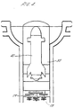
- a seabed enclosure in the form of an upright outer cylindrical container 10 which terminates in a cup shape head 11 at its upper end and has an open lower end 12.
- the container is manufactured from anechoic materials.
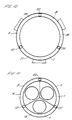
- the container and cup shaped housing are both of double walled construction as best seen in Figures 2 and 3, the outer wall being indicated at 13 and the inner wall being indicated at 14.
- the space between the inner and outer wall is divided into three sectors A, B and C by three internal partitions 15.
- the partitions are wound spirally around the container as they extend between lower end of the container and the upper of the cup shaped housing for a purpose to be described below.
- the cavities A, B and C have corresponding inlets 16, 17 and 18 at the bottom end of the outer container and the open space at the bottom end of the container indicated at 19 on Figure 1 is similarly divided into three sectors 20, 21 and 22 by partition 23.
- the cup shaped housing is located at the lower end of the container and is ballasted to make that end heavier and a buoyancy chamber is provided at the upper end.
- impeller/propellers 28 are mounted in the respective sectors 20, 21 and 22.
- the impeller/propellers are driven by drive motors mounted in a sealed compartment indicated at 29 and powered by compressed air, gas or batteries housed in a compartment above indicated at 30.
- the impeller/propellers may have augers 28a which engage and stir-up sand, silt or shingle on the seabed.
- the resulting mixture of water and sand/silt/shingle can enter the inlets 16, 17 and 18 at the bottom of the container and flow upwardly through the spiral passages to exit from the outlets 25, 26 and 27 in the outwardly facing flange at the top of the cup shaped housing at the head of the container to deposit on the seabed around the container.
- the container can self bury into the seabed.
- the compartment 32 projects upwardly into the cup shaped housing and has a releasable domed shaped cap 33.
- the space in the cup shaped housing 11 around the upper end of the compartment 32 is occupied by a buoyancy chamber 34 which ensures that the upper end of the container is more buoyant than the lower end so that as the container sinks in the water after being released, it is vertically orientated as illustrated.
- side thruster pumps 35 are mounted on the outside of the cup shaped housing controlled by the gyro/control equipment disposed in the compartment 31. The pumps ensure vertical alignment of the container as it lowers into the seabed.
- Figure 4 of the drawings shows an application of the device in which the payload compartment 32 contains a weapon 40 and Figure 5 of the drawings shows an application of the device in which the payload compartment 32 contain communication buoys 41.
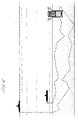
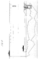
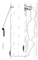
- Figures 6 to 9 show the enclosure buried in the seabed and receiving signals from a surface ship and a submarine.
- the cup shaped housing of the container is clear of the seabed.
- the housing is shown embedded in sand/silt which would typically happen after a period of time.
- a communication device has been released from the payload compartment and is rising to the surface and in Figure 9 the device has reached the surface and is transmitting a signal to an overflying aircraft.
- the device may include G.P.S. (global positioning system) so that a signal representing the precise position of the device may be transmitted.
- G.P.S. global positioning system
- Figures 6 to 9 illustrate communication with vessels through the seabed itself.
- the control department may be provided with one or more devices responsive to vibration, noise and signals transmitted through the seabed.
- the device could be a magnomometer, a seismometer, Rayleigh disc or the like.
- the compartment may also including recording and processing equipment which could interface with communications equipment in the payload compartment for transmitting information corresponding to signals received when the communication device is despatched to the surface.
- the P. Waves generated by C.B. of the propellers of approaching vessels are likely to be much easier to classify - identify when transmitted through the medium of the sea bed and then stored - analysed, processed by instrumentation within a buried can.
- the information gathered e.g. - course, speed-depths and classification could then be transmitted via the radio beacons thereby alerting friendly vessels to the approach of potentially hostile forces, well in advance of their arrival.
- the descent of the can through water to the seabed may be controlled either by, or in combination as follows:
- All motors-propellers will be controlled from a gyroscope pre-set to maintain a desired position-attitude when uncaged and operating.
- the equipment needed to interpret and analyse the signals received may also be mounted on a Gyro stabilised platform, or within similarly stabilised inner container, thus ensuring the instruments are finely tuned to a pre-determined position.
- the propellers/impellers on the lower side of the bottom of the can will slow-stop, while that on the opposite higher side will continue to operate thereby attempting to maintain the desired angle of entry.
- the efflux through the port of the top of the can positioned at 180° to the inlet, will assist as will the thruster pumps, which will also be actuated to assist in maintaining the desired angle of entry.
- a reversing control may be embodied in the system allowing them to operate in the reverse direction, accompanied by pulses of air-water thereby assisting in overcoming any obstruction.
- the Payload chamber may be adapted to carry Varying payloads e.g.
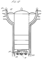
- FIG. 10 to 12 of the drawings illustrate a modified form of the container.
- the internal partitions between the inner and outer walls of the container are replaced by conduits 50 extending between the upper and lower ends of the container.
- the conduits are connected to an annular manifold 51 encircling the head of the container and are connected to a motor driven water pump 52 mounted in the cup shaped head for delivering water into the manifold distribution to the conduits.
- conduits 52 At the lower end 12 of the container the conduits 52 have discharge nozzles 53 for directing water flow into the cavity 19 to assist in the scouring action of the impeller/ propellers 28 to maintain the sand/silt/shingle released from the seabed by the impellers in a fluid state to be drawn up through the inlets 16, 17 and 18 to the top of the container to exit from the outlets 25, 26 and 27 as described earlier.
Landscapes
- Life Sciences & Earth Sciences (AREA)
- Engineering & Computer Science (AREA)
- Physics & Mathematics (AREA)
- General Life Sciences & Earth Sciences (AREA)
- Geophysics (AREA)
- Environmental & Geological Engineering (AREA)
- Geology (AREA)
- Remote Sensing (AREA)
- Acoustics & Sound (AREA)
- General Physics & Mathematics (AREA)
- Oceanography (AREA)
- General Engineering & Computer Science (AREA)
- Mechanical Engineering (AREA)
- Ocean & Marine Engineering (AREA)
- Geophysics And Detection Of Objects (AREA)
- Artificial Fish Reefs (AREA)
- Cultivation Of Seaweed (AREA)
- Measurement And Recording Of Electrical Phenomena And Electrical Characteristics Of The Living Body (AREA)
- Earth Drilling (AREA)
Claims (11)
- Enceinte à installer dans ou sur le fond de la mer, comprenant un conteneur cylindrique extérieur (10) ayant des moyens pour faire en sorte qu'une extrémité particulière du conteneur flotte mieux que l'autre extrémité, de sorte que le conteneur repose à la verticale quand il est disposé dans la mer, et ayant des moyens au niveau de l'autre extrémité pour activer les sable/limon/galets sur le fond de la mer pour créer une cavité au-dessous du conteneur dans laquelle le conteneur peut s'enterrer ; caractérisée en ce que le conteneur a un compartiment de charge utile à l'intérieur du conteneur pour contenir un équipement d'armement, d'écoute, d'enregistrement d'identification et/ou de communication ; et en ce que la paroi du conteneur est formée par une pluralité de passages espacés (A, B, C) s'étendant en spirale à partir des entrées (16, 17, 18) au niveau de l'extrémité inférieure du conteneur vers le haut vers des sorties (25, 26, 27) au niveau du sommet du conteneur à travers lesquels les sable/limon/galets activés et l'eau produite au niveau de l'extrémité inférieure du conteneur peuvent s'écouler vers le haut et librement lorsque le conteneur s'enterre dans le fond de la mer.
- Enceinte selon la revendication 1, caractérisée en ce que le conteneur possède des parois concentriques intérieure (14) et extérieure (13) divisées pour former une pluralité de voies de passage s'étendant en spirale (A, B, C) menant depuis des entrées (16, 17, 18) au niveau de l'extrémité inférieure du conteneur jusqu'à des sorties (25, 26, 27) au niveau de l'extrémité supérieure du conteneur pour amener du sable/limon/galets et de l'eau activés au niveau de l'extrémité inférieure du conteneur vers l'extrémité supérieure du conteneur.
- Enceinte selon la revendication 2, caractérisée en ce que lesdites entrées sont formées entre les parois concentriques du côté intérieur du conteneur au niveau de l'extrémité inférieure de ce dernier.
- Enceinte selon la revendication 2 ou la revendication 3, caractérisée en ce que lesdites sorties sont formées dans la périphérie extérieure de l'extrémité supérieure du conteneur.
- Enceinte selon l'une quelconque des revendications précédentes, caractérisée en ce que l'extrémité supérieure du conteneur a une tête en forme de coupelle à travers laquelle lesdits passages (A, B, C) s'étendent vers des sorties (25, 26, 27) au niveau de la périphérie extérieure de la coupelle et une chambre de flottaison est formée à l'intérieur de la coupelle pour faire en sorte que l'extrémité supérieure du conteneur flotte mieux que l'extrémité inférieure, comme on l'a précédemment mentionné.
- Enceinte selon l'une quelconque des revendications précédentes, caractérisée en ce qu'une pluralité de turbines/hélices entraínées par moteur (28) sont montées à l'intérieur de l'extrémité inférieure du conteneur pour agir sur le fond de la mer au-dessous, à côté de l'entrée respective vers les passages à travers la paroi du conteneur.
- Enceinte selon l'une quelconque des revendications précédentes, caractérisée en ce que les pompes de propulseur sont disposées à des emplacements espacés autour de l'extrémité supérieure du conteneur pour maintenir le conteneur vertical quand il s'enterre dans le fond de la mer et le conteneur intérieur possède un équipement de commande gyroscopique pour commander les pompes de propulseur.
- Enceinte selon l'une quelconque des revendications précédentes, caractérisée en ce que le conteneur intérieur comprend des moyens pour détecter des signaux, des vibrations ou des bruits transmis par l'intermédiaire du fond de la mer pour activer l'équipement d'armement et/ou de communication enfermé dans le conteneur intérieur.
- Enceinte selon l'une quelconque des revendications précédentes, caractérisée en ce que des moyens sont prévus pour pomper de l'eau à partir de l'extrémité supérieure du conteneur vers l'extrémité inférieure du conteneur pour aider à maintenir le mélange de sable/limon libéré du fond de la mer dans un état fluide pour être extrait à travers le conteneur.
- Enceinte selon la revendication 9, caractérisée en ce que lesdits moyens pour amener de l'eau vers l'extrémité inférieure du conteneur comprennent des conduites s'étendant depuis l'extrémité supérieure vers l'extrémité inférieure du conteneur entre les passages s'étendant en spirale pour amener du sable/limon et de l'eau activés depuis l'extrémité inférieure du conteneur vers l'extrémité supérieure du conteneur, les moyens formant pompes ayant des buses de décharge au niveau de l'extrémité inférieure du conteneur et lesdits moyens formant pompes étant reliés à l'extrémité supérieure du conteneur.
- Enceinte selon la revendication 10, caractérisée en ce que les entrées vers les conduites au niveau de l'extrémité supérieure du conteneur sont reliées à un collecteur entourant l'extrémité supérieure du conteneur et en ce que la pompe est montée dans l'extrémité supérieure du conteneur pour pomper de l'eau vers le collecteur pour l'amener au moyen desdites conduites vers les buses à l'extrémité de fond du conteneur.
Applications Claiming Priority (3)
| Application Number | Priority Date | Filing Date | Title |
|---|---|---|---|
| GB9516752 | 1995-08-16 | ||
| GBGB9516752.4A GB9516752D0 (en) | 1995-08-16 | 1995-08-16 | Improvements in or relating to seabed enclosures |
| PCT/GB1996/001945 WO1997007017A1 (fr) | 1995-08-16 | 1996-08-09 | Ameliorations apportees ou relatives aux enceintes pour fond sous-marin |
Publications (2)
| Publication Number | Publication Date |
|---|---|
| EP0844963A1 EP0844963A1 (fr) | 1998-06-03 |
| EP0844963B1 true EP0844963B1 (fr) | 2000-06-28 |
Family
ID=10779300
Family Applications (1)
| Application Number | Title | Priority Date | Filing Date |
|---|---|---|---|
| EP96927137A Expired - Lifetime EP0844963B1 (fr) | 1995-08-16 | 1996-08-09 | Ameliorations apportees ou relatives aux enceintes pour fond sous-marin |
Country Status (7)
| Country | Link |
|---|---|
| US (1) | US6044745A (fr) |
| EP (1) | EP0844963B1 (fr) |
| AT (1) | ATE194112T1 (fr) |
| AU (1) | AU694058B2 (fr) |
| DE (1) | DE69609072T2 (fr) |
| GB (1) | GB9516752D0 (fr) |
| WO (1) | WO1997007017A1 (fr) |
Cited By (5)
| Publication number | Priority date | Publication date | Assignee | Title |
|---|---|---|---|---|
| EP1092937A2 (fr) | 1999-10-13 | 2001-04-18 | Lawborough Consultants Limited | Conteneur pour installation dans le fond de la mer |
| US6505452B1 (en) | 1999-06-30 | 2003-01-14 | Akzenta Paneele + Profile Gmbh | Panel and fastening system for panels |
| US7065935B2 (en) | 1999-07-02 | 2006-06-27 | Akzenta Paneele & Profile Gmbh | Method for laying and interlocking panels |
| US7451578B2 (en) | 2001-08-10 | 2008-11-18 | Akzenta Paneele + Profile Gmbh | Panel and fastening system for such a panel |
| US20140209003A1 (en) * | 2012-12-27 | 2014-07-31 | Japan System Planning Co., Ltd. | Sea-based buoyancy type torpedo storage and launch system, torpedo storage and launch apparatus, and buoyant rise type torpedo |
Families Citing this family (17)
| Publication number | Priority date | Publication date | Assignee | Title |
|---|---|---|---|---|
| US6951138B1 (en) * | 2000-11-01 | 2005-10-04 | Westerngeco L.L.C. | Method and apparatus for an ocean bottom seismic acquisition technique |
| GB2368560A (en) | 2000-11-02 | 2002-05-08 | Lawborough Consultants Ltd | Vessel and apparatus for clearing seabed mines |
| GB2377412A (en) | 2000-11-03 | 2003-01-15 | Lawborough Consultants Ltd | Support vessel for self-burying mines |
| US8293808B2 (en) | 2003-09-30 | 2012-10-23 | Cargill, Incorporated | Flexible polyurethane foams prepared using modified vegetable oil-based polyols |
| WO2006012344A1 (fr) | 2004-06-25 | 2006-02-02 | Pittsburg State University | Polyols a base d'huile vegetale modifiee |
| US8161899B1 (en) * | 2008-09-11 | 2012-04-24 | The United States Of America As Represented By The Secretary Of The Navy | Multiple torpedo mine |
| GB201116285D0 (en) * | 2011-09-21 | 2011-11-02 | Go Science Ltd | Deployment of seabed device |
| US9383471B2 (en) * | 2012-09-14 | 2016-07-05 | Cgg Services Sa | Method and underwater node for seismic survey |
| US9381986B2 (en) | 2012-11-21 | 2016-07-05 | Seabed Geosolutions B.V. | Jet-pump-based autonomous underwater vehicle and method for coupling to ocean bottom during marine seismic survey |
| WO2014090811A2 (fr) * | 2012-12-10 | 2014-06-19 | Cgg Services Sa | Système et procédé de contrôle sismique en mer |
| US9457879B2 (en) | 2012-12-17 | 2016-10-04 | Seabed Geosolutions B.V. | Self-burying autonomous underwater vehicle and method for marine seismic surveys |
| US9417351B2 (en) * | 2012-12-21 | 2016-08-16 | Cgg Services Sa | Marine seismic surveys using clusters of autonomous underwater vehicles |
| US20150003194A1 (en) * | 2013-06-26 | 2015-01-01 | Cgg Services Sa | Directional self-burying sensor system and method |
| CZ28566U1 (cs) * | 2014-10-06 | 2015-08-31 | Vysoká škola báňská- Technická univerzita Ostrava | Zařízení pro snímání mechanicko-fyzikálních a optických veličin sypkých hmot |
| US10571222B2 (en) * | 2017-09-07 | 2020-02-25 | Stephen Tomás Strocchia-Rivera | Payload launching apparatus and method |
| CN110319734B (zh) * | 2019-07-11 | 2020-06-19 | 北京航空航天大学 | 地埋式伪装小型运载火箭发射系统 |
| CN110319733B (zh) * | 2019-07-11 | 2020-06-19 | 北京航空航天大学 | 地埋式伪装导弹发射系统 |
Family Cites Families (8)
| Publication number | Priority date | Publication date | Assignee | Title |
|---|---|---|---|---|
| US3035285A (en) * | 1961-09-18 | 1962-05-22 | Jr Walter G Squires | Explosively anchored buoy |
| CH503847A (de) * | 1969-02-27 | 1971-02-28 | Mengis Geb | Vorrichtung zum Ziehen eines Grabens und Verfahren zum Betrieb derselben |
| DE2154231A1 (de) * | 1971-10-30 | 1973-05-03 | Erno Raumfahrttechnik Gmbh | Bohrankeranordnung |
| GB2048439B (en) * | 1979-04-30 | 1982-12-15 | Lawborough Consultants Ltd | Underwater weapons |
| US4395952A (en) * | 1980-12-04 | 1983-08-02 | Hickey Christopher D D | Underwater weapon systems |
| DE3380273D1 (en) * | 1982-10-28 | 1989-08-31 | Underwater Storage Ltd | Underwater weapon systems |
| GB2134232B (en) * | 1982-12-10 | 1986-07-02 | Underwater Storage Ltd | Underwater weapon system |
| US5837919A (en) * | 1996-12-05 | 1998-11-17 | The United States Of America As Represented By The Secretary Of The Navy | Portable launcher |
-
1995
- 1995-08-16 GB GBGB9516752.4A patent/GB9516752D0/en active Pending
-
1996
- 1996-08-09 DE DE69609072T patent/DE69609072T2/de not_active Expired - Fee Related
- 1996-08-09 EP EP96927137A patent/EP0844963B1/fr not_active Expired - Lifetime
- 1996-08-09 AT AT96927137T patent/ATE194112T1/de not_active IP Right Cessation
- 1996-08-09 US US09/011,651 patent/US6044745A/en not_active Expired - Lifetime
- 1996-08-09 AU AU67068/96A patent/AU694058B2/en not_active Ceased
- 1996-08-09 WO PCT/GB1996/001945 patent/WO1997007017A1/fr not_active Ceased
Cited By (9)
| Publication number | Priority date | Publication date | Assignee | Title |
|---|---|---|---|---|
| US6505452B1 (en) | 1999-06-30 | 2003-01-14 | Akzenta Paneele + Profile Gmbh | Panel and fastening system for panels |
| US7065935B2 (en) | 1999-07-02 | 2006-06-27 | Akzenta Paneele & Profile Gmbh | Method for laying and interlocking panels |
| US7856789B2 (en) * | 1999-07-02 | 2010-12-28 | Akzenta Paneele & Profile Gmbh | Method for laying and interlocking panels |
| EP1092937A2 (fr) | 1999-10-13 | 2001-04-18 | Lawborough Consultants Limited | Conteneur pour installation dans le fond de la mer |
| EP1092937A3 (fr) * | 1999-10-13 | 2002-04-03 | Lawborough Consultants Limited | Conteneur pour installation dans le fond de la mer |
| US6371003B1 (en) | 1999-10-13 | 2002-04-16 | Lawborough Consultants Limited | Enclosures for installation on the seabed |
| US7451578B2 (en) | 2001-08-10 | 2008-11-18 | Akzenta Paneele + Profile Gmbh | Panel and fastening system for such a panel |
| US20140209003A1 (en) * | 2012-12-27 | 2014-07-31 | Japan System Planning Co., Ltd. | Sea-based buoyancy type torpedo storage and launch system, torpedo storage and launch apparatus, and buoyant rise type torpedo |
| US9200879B2 (en) * | 2012-12-27 | 2015-12-01 | Japan System Planning Co., Ltd. | Sea-based buoyancy type torpedo storage and launch system, torpedo storage and launch apparatus, and buoyant rise type torpedo |
Also Published As
| Publication number | Publication date |
|---|---|
| DE69609072T2 (de) | 2001-03-22 |
| DE69609072D1 (de) | 2000-08-03 |
| US6044745A (en) | 2000-04-04 |
| WO1997007017A1 (fr) | 1997-02-27 |
| AU694058B2 (en) | 1998-07-09 |
| AU6706896A (en) | 1997-03-12 |
| EP0844963A1 (fr) | 1998-06-03 |
| ATE194112T1 (de) | 2000-07-15 |
| GB9516752D0 (en) | 1995-10-18 |
Similar Documents
| Publication | Publication Date | Title |
|---|---|---|
| EP0844963B1 (fr) | Ameliorations apportees ou relatives aux enceintes pour fond sous-marin | |
| US11267546B2 (en) | Ocean bottom seismic autonomous underwater vehicle | |
| EP0537159B1 (fr) | Systeme et appareil de recuperation d'hydrocarbures | |
| US9381984B2 (en) | Apparatus for subsea transport of sensor systems | |
| US7496002B2 (en) | Water submersible electronics assembly and methods of use | |
| JPS58772B2 (ja) | 深海用自動推進無人潜水船 | |
| US4586421A (en) | Underwater weapon systems | |
| JP5923169B2 (ja) | 通信ブイおよび展開の方法 | |
| CN102007251A (zh) | 采油系统和装置 | |
| US6002648A (en) | Slotted cylinder marine siesmic method and source | |
| US11255998B2 (en) | Cathedral body structure for an ocean bottom seismic node | |
| US7736094B1 (en) | Self-contained burying device for submerged environments | |
| EP1092937B1 (fr) | Conteneur pour installation dans le fond de la mer | |
| JP2024066406A (ja) | ドローン搭載用カプセルおよびこれを用いた潜水艦の監視偵察システム | |
| AU2021292366B8 (en) | Floating or submersible body for acoustic position finding, in particular for de-mining activities | |
| US6069842A (en) | Method and device for helicopter-borne mine countermeasures | |
| US6052332A (en) | Countermeasure flexible line array | |
| CA2324084A1 (fr) | Systeme d'imagerie pour detecter des objets souterrains ou immerges, et procedes correspondants | |
| JPH02290580A (ja) | 水中探知装置 | |
| Dzielski et al. | NAVOCEANO Seahorse AUV design, testing, and capabilities | |
| JPS60148992A (ja) | 海底鉱物採掘装置における潜水モジユ−ル装置 | |
| US20020088365A1 (en) | Support vessel for self-burying mines | |
| JP2021054378A (ja) | 水底形状測定装置 | |
| EP3204732B1 (fr) | Dispositif pour détecter des caracteristques mécaniques - physiques et optiques des matériaux en vrac | |
| WO2025230426A1 (fr) | Ensemble nœud |
Legal Events
| Date | Code | Title | Description |
|---|---|---|---|
| PUAI | Public reference made under article 153(3) epc to a published international application that has entered the european phase |
Free format text: ORIGINAL CODE: 0009012 |
|
| 17P | Request for examination filed |
Effective date: 19980219 |
|
| AK | Designated contracting states |
Kind code of ref document: A1 Designated state(s): AT BE CH DE DK ES FI FR GB GR IE IT LI LU MC NL PT SE |
|
| 17Q | First examination report despatched |
Effective date: 19980618 |
|
| GRAG | Despatch of communication of intention to grant |
Free format text: ORIGINAL CODE: EPIDOS AGRA |
|
| RAP1 | Party data changed (applicant data changed or rights of an application transferred) |
Owner name: LAWBOROUGH CONSULTANTS LIMITED |
|
| GRAG | Despatch of communication of intention to grant |
Free format text: ORIGINAL CODE: EPIDOS AGRA |
|
| GRAH | Despatch of communication of intention to grant a patent |
Free format text: ORIGINAL CODE: EPIDOS IGRA |
|
| GRAH | Despatch of communication of intention to grant a patent |
Free format text: ORIGINAL CODE: EPIDOS IGRA |
|
| ITF | It: translation for a ep patent filed | ||
| GRAA | (expected) grant |
Free format text: ORIGINAL CODE: 0009210 |
|
| AK | Designated contracting states |
Kind code of ref document: B1 Designated state(s): AT BE CH DE DK ES FI FR GB GR IE IT LI LU MC NL PT SE |
|
| PG25 | Lapsed in a contracting state [announced via postgrant information from national office to epo] |
Ref country code: NL Free format text: LAPSE BECAUSE OF FAILURE TO SUBMIT A TRANSLATION OF THE DESCRIPTION OR TO PAY THE FEE WITHIN THE PRESCRIBED TIME-LIMIT Effective date: 20000628 Ref country code: LI Free format text: LAPSE BECAUSE OF FAILURE TO SUBMIT A TRANSLATION OF THE DESCRIPTION OR TO PAY THE FEE WITHIN THE PRESCRIBED TIME-LIMIT Effective date: 20000628 Ref country code: GR Free format text: LAPSE BECAUSE OF NON-PAYMENT OF DUE FEES Effective date: 20000628 Ref country code: FI Free format text: LAPSE BECAUSE OF FAILURE TO SUBMIT A TRANSLATION OF THE DESCRIPTION OR TO PAY THE FEE WITHIN THE PRESCRIBED TIME-LIMIT Effective date: 20000628 Ref country code: ES Free format text: THE PATENT HAS BEEN ANNULLED BY A DECISION OF A NATIONAL AUTHORITY Effective date: 20000628 Ref country code: CH Free format text: LAPSE BECAUSE OF FAILURE TO SUBMIT A TRANSLATION OF THE DESCRIPTION OR TO PAY THE FEE WITHIN THE PRESCRIBED TIME-LIMIT Effective date: 20000628 Ref country code: BE Free format text: LAPSE BECAUSE OF FAILURE TO SUBMIT A TRANSLATION OF THE DESCRIPTION OR TO PAY THE FEE WITHIN THE PRESCRIBED TIME-LIMIT Effective date: 20000628 Ref country code: AT Free format text: LAPSE BECAUSE OF FAILURE TO SUBMIT A TRANSLATION OF THE DESCRIPTION OR TO PAY THE FEE WITHIN THE PRESCRIBED TIME-LIMIT Effective date: 20000628 |
|
| REF | Corresponds to: |
Ref document number: 194112 Country of ref document: AT Date of ref document: 20000715 Kind code of ref document: T |
|
| REG | Reference to a national code |
Ref country code: CH Ref legal event code: EP |
|
| REG | Reference to a national code |
Ref country code: IE Ref legal event code: FG4D |
|
| REF | Corresponds to: |
Ref document number: 69609072 Country of ref document: DE Date of ref document: 20000803 |
|
| ET | Fr: translation filed | ||
| PG25 | Lapsed in a contracting state [announced via postgrant information from national office to epo] |
Ref country code: LU Free format text: LAPSE BECAUSE OF NON-PAYMENT OF DUE FEES Effective date: 20000809 Ref country code: IE Free format text: LAPSE BECAUSE OF NON-PAYMENT OF DUE FEES Effective date: 20000809 |
|
| PG25 | Lapsed in a contracting state [announced via postgrant information from national office to epo] |
Ref country code: MC Free format text: THE PATENT HAS BEEN ANNULLED BY A DECISION OF A NATIONAL AUTHORITY Effective date: 20000831 |
|
| PG25 | Lapsed in a contracting state [announced via postgrant information from national office to epo] |
Ref country code: SE Free format text: LAPSE BECAUSE OF FAILURE TO SUBMIT A TRANSLATION OF THE DESCRIPTION OR TO PAY THE FEE WITHIN THE PRESCRIBED TIME-LIMIT Effective date: 20000928 Ref country code: PT Free format text: LAPSE BECAUSE OF FAILURE TO SUBMIT A TRANSLATION OF THE DESCRIPTION OR TO PAY THE FEE WITHIN THE PRESCRIBED TIME-LIMIT Effective date: 20000928 Ref country code: DK Free format text: LAPSE BECAUSE OF FAILURE TO SUBMIT A TRANSLATION OF THE DESCRIPTION OR TO PAY THE FEE WITHIN THE PRESCRIBED TIME-LIMIT Effective date: 20000928 |
|
| NLV1 | Nl: lapsed or annulled due to failure to fulfill the requirements of art. 29p and 29m of the patents act | ||
| REG | Reference to a national code |
Ref country code: CH Ref legal event code: PL |
|
| PLBE | No opposition filed within time limit |
Free format text: ORIGINAL CODE: 0009261 |
|
| STAA | Information on the status of an ep patent application or granted ep patent |
Free format text: STATUS: NO OPPOSITION FILED WITHIN TIME LIMIT |
|
| REG | Reference to a national code |
Ref country code: IE Ref legal event code: MM4A |
|
| 26N | No opposition filed | ||
| REG | Reference to a national code |
Ref country code: GB Ref legal event code: IF02 |
|
| GBPC | Gb: european patent ceased through non-payment of renewal fee |
Effective date: 20050809 |
|
| PGFP | Annual fee paid to national office [announced via postgrant information from national office to epo] |
Ref country code: FR Payment date: 20060718 Year of fee payment: 11 |
|
| PGFP | Annual fee paid to national office [announced via postgrant information from national office to epo] |
Ref country code: IT Payment date: 20060831 Year of fee payment: 11 |
|
| REG | Reference to a national code |
Ref country code: GB Ref legal event code: 728V |
|
| PGFP | Annual fee paid to national office [announced via postgrant information from national office to epo] |
Ref country code: DE Payment date: 20061030 Year of fee payment: 11 |
|
| REG | Reference to a national code |
Ref country code: GB Ref legal event code: 728Y |
|
| REG | Reference to a national code |
Ref country code: FR Ref legal event code: ST Effective date: 20080430 |
|
| PG25 | Lapsed in a contracting state [announced via postgrant information from national office to epo] |
Ref country code: DE Free format text: LAPSE BECAUSE OF NON-PAYMENT OF DUE FEES Effective date: 20080301 |
|
| PG25 | Lapsed in a contracting state [announced via postgrant information from national office to epo] |
Ref country code: FR Free format text: LAPSE BECAUSE OF NON-PAYMENT OF DUE FEES Effective date: 20070831 |
|
| PG25 | Lapsed in a contracting state [announced via postgrant information from national office to epo] |
Ref country code: IT Free format text: LAPSE BECAUSE OF NON-PAYMENT OF DUE FEES Effective date: 20070809 |
|
| PGFP | Annual fee paid to national office [announced via postgrant information from national office to epo] |
Ref country code: GB Payment date: 20110825 Year of fee payment: 16 |
|
| GBPC | Gb: european patent ceased through non-payment of renewal fee |
Effective date: 20120809 |
|
| PG25 | Lapsed in a contracting state [announced via postgrant information from national office to epo] |
Ref country code: GB Free format text: LAPSE BECAUSE OF NON-PAYMENT OF DUE FEES Effective date: 20120809 |