EP0845088B1 - System zur aktiven verringerung von radialschwingungen einer rotierenden welle sowie hierfür geeignete verfahren - Google Patents
System zur aktiven verringerung von radialschwingungen einer rotierenden welle sowie hierfür geeignete verfahren Download PDFInfo
- Publication number
- EP0845088B1 EP0845088B1 EP96937993A EP96937993A EP0845088B1 EP 0845088 B1 EP0845088 B1 EP 0845088B1 EP 96937993 A EP96937993 A EP 96937993A EP 96937993 A EP96937993 A EP 96937993A EP 0845088 B1 EP0845088 B1 EP 0845088B1
- Authority
- EP
- European Patent Office
- Prior art keywords
- radial
- shaft
- active
- vibrations
- electric machine
- Prior art date
- Legal status (The legal status is an assumption and is not a legal conclusion. Google has not performed a legal analysis and makes no representation as to the accuracy of the status listed.)
- Expired - Lifetime
Links
Images


Classifications
-
- B—PERFORMING OPERATIONS; TRANSPORTING
- B60—VEHICLES IN GENERAL
- B60W—CONJOINT CONTROL OF VEHICLE SUB-UNITS OF DIFFERENT TYPE OR DIFFERENT FUNCTION; CONTROL SYSTEMS SPECIALLY ADAPTED FOR HYBRID VEHICLES; ROAD VEHICLE DRIVE CONTROL SYSTEMS FOR PURPOSES NOT RELATED TO THE CONTROL OF A PARTICULAR SUB-UNIT
- B60W20/00—Control systems specially adapted for hybrid vehicles
-
- B—PERFORMING OPERATIONS; TRANSPORTING
- B60—VEHICLES IN GENERAL
- B60K—ARRANGEMENT OR MOUNTING OF PROPULSION UNITS OR OF TRANSMISSIONS IN VEHICLES; ARRANGEMENT OR MOUNTING OF PLURAL DIVERSE PRIME-MOVERS IN VEHICLES; AUXILIARY DRIVES FOR VEHICLES; INSTRUMENTATION OR DASHBOARDS FOR VEHICLES; ARRANGEMENTS IN CONNECTION WITH COOLING, AIR INTAKE, GAS EXHAUST OR FUEL SUPPLY OF PROPULSION UNITS IN VEHICLES
- B60K6/00—Arrangement or mounting of plural diverse prime-movers for mutual or common propulsion, e.g. hybrid propulsion systems comprising electric motors and internal combustion engines
- B60K6/20—Arrangement or mounting of plural diverse prime-movers for mutual or common propulsion, e.g. hybrid propulsion systems comprising electric motors and internal combustion engines the prime-movers consisting of electric motors and internal combustion engines, e.g. HEVs
- B60K6/22—Arrangement or mounting of plural diverse prime-movers for mutual or common propulsion, e.g. hybrid propulsion systems comprising electric motors and internal combustion engines the prime-movers consisting of electric motors and internal combustion engines, e.g. HEVs characterised by apparatus, components or means specially adapted for HEVs
- B60K6/28—Arrangement or mounting of plural diverse prime-movers for mutual or common propulsion, e.g. hybrid propulsion systems comprising electric motors and internal combustion engines the prime-movers consisting of electric motors and internal combustion engines, e.g. HEVs characterised by apparatus, components or means specially adapted for HEVs characterised by the electric energy storing means, e.g. batteries or capacitors
-
- B—PERFORMING OPERATIONS; TRANSPORTING
- B60—VEHICLES IN GENERAL
- B60K—ARRANGEMENT OR MOUNTING OF PROPULSION UNITS OR OF TRANSMISSIONS IN VEHICLES; ARRANGEMENT OR MOUNTING OF PLURAL DIVERSE PRIME-MOVERS IN VEHICLES; AUXILIARY DRIVES FOR VEHICLES; INSTRUMENTATION OR DASHBOARDS FOR VEHICLES; ARRANGEMENTS IN CONNECTION WITH COOLING, AIR INTAKE, GAS EXHAUST OR FUEL SUPPLY OF PROPULSION UNITS IN VEHICLES
- B60K6/00—Arrangement or mounting of plural diverse prime-movers for mutual or common propulsion, e.g. hybrid propulsion systems comprising electric motors and internal combustion engines
- B60K6/20—Arrangement or mounting of plural diverse prime-movers for mutual or common propulsion, e.g. hybrid propulsion systems comprising electric motors and internal combustion engines the prime-movers consisting of electric motors and internal combustion engines, e.g. HEVs
- B60K6/22—Arrangement or mounting of plural diverse prime-movers for mutual or common propulsion, e.g. hybrid propulsion systems comprising electric motors and internal combustion engines the prime-movers consisting of electric motors and internal combustion engines, e.g. HEVs characterised by apparatus, components or means specially adapted for HEVs
- B60K6/38—Arrangement or mounting of plural diverse prime-movers for mutual or common propulsion, e.g. hybrid propulsion systems comprising electric motors and internal combustion engines the prime-movers consisting of electric motors and internal combustion engines, e.g. HEVs characterised by apparatus, components or means specially adapted for HEVs characterised by the driveline clutches
-
- B—PERFORMING OPERATIONS; TRANSPORTING
- B60—VEHICLES IN GENERAL
- B60K—ARRANGEMENT OR MOUNTING OF PROPULSION UNITS OR OF TRANSMISSIONS IN VEHICLES; ARRANGEMENT OR MOUNTING OF PLURAL DIVERSE PRIME-MOVERS IN VEHICLES; AUXILIARY DRIVES FOR VEHICLES; INSTRUMENTATION OR DASHBOARDS FOR VEHICLES; ARRANGEMENTS IN CONNECTION WITH COOLING, AIR INTAKE, GAS EXHAUST OR FUEL SUPPLY OF PROPULSION UNITS IN VEHICLES
- B60K6/00—Arrangement or mounting of plural diverse prime-movers for mutual or common propulsion, e.g. hybrid propulsion systems comprising electric motors and internal combustion engines
- B60K6/20—Arrangement or mounting of plural diverse prime-movers for mutual or common propulsion, e.g. hybrid propulsion systems comprising electric motors and internal combustion engines the prime-movers consisting of electric motors and internal combustion engines, e.g. HEVs
- B60K6/22—Arrangement or mounting of plural diverse prime-movers for mutual or common propulsion, e.g. hybrid propulsion systems comprising electric motors and internal combustion engines the prime-movers consisting of electric motors and internal combustion engines, e.g. HEVs characterised by apparatus, components or means specially adapted for HEVs
- B60K6/38—Arrangement or mounting of plural diverse prime-movers for mutual or common propulsion, e.g. hybrid propulsion systems comprising electric motors and internal combustion engines the prime-movers consisting of electric motors and internal combustion engines, e.g. HEVs characterised by apparatus, components or means specially adapted for HEVs characterised by the driveline clutches
- B60K6/387—Actuated clutches, i.e. clutches engaged or disengaged by electric, hydraulic or mechanical actuating means
-
- B—PERFORMING OPERATIONS; TRANSPORTING
- B60—VEHICLES IN GENERAL
- B60K—ARRANGEMENT OR MOUNTING OF PROPULSION UNITS OR OF TRANSMISSIONS IN VEHICLES; ARRANGEMENT OR MOUNTING OF PLURAL DIVERSE PRIME-MOVERS IN VEHICLES; AUXILIARY DRIVES FOR VEHICLES; INSTRUMENTATION OR DASHBOARDS FOR VEHICLES; ARRANGEMENTS IN CONNECTION WITH COOLING, AIR INTAKE, GAS EXHAUST OR FUEL SUPPLY OF PROPULSION UNITS IN VEHICLES
- B60K6/00—Arrangement or mounting of plural diverse prime-movers for mutual or common propulsion, e.g. hybrid propulsion systems comprising electric motors and internal combustion engines
- B60K6/20—Arrangement or mounting of plural diverse prime-movers for mutual or common propulsion, e.g. hybrid propulsion systems comprising electric motors and internal combustion engines the prime-movers consisting of electric motors and internal combustion engines, e.g. HEVs
- B60K6/42—Arrangement or mounting of plural diverse prime-movers for mutual or common propulsion, e.g. hybrid propulsion systems comprising electric motors and internal combustion engines the prime-movers consisting of electric motors and internal combustion engines, e.g. HEVs characterised by the architecture of the hybrid electric vehicle
- B60K6/48—Parallel type
- B60K6/485—Motor-assist type
-
- B—PERFORMING OPERATIONS; TRANSPORTING
- B60—VEHICLES IN GENERAL
- B60L—PROPULSION OF ELECTRICALLY-PROPELLED VEHICLES; SUPPLYING ELECTRIC POWER FOR AUXILIARY EQUIPMENT OF ELECTRICALLY-PROPELLED VEHICLES; ELECTRODYNAMIC BRAKE SYSTEMS FOR VEHICLES IN GENERAL; MAGNETIC SUSPENSION OR LEVITATION FOR VEHICLES; MONITORING OPERATING VARIABLES OF ELECTRICALLY-PROPELLED VEHICLES; ELECTRIC SAFETY DEVICES FOR ELECTRICALLY-PROPELLED VEHICLES
- B60L1/00—Supplying electric power to auxiliary equipment of vehicles
- B60L1/003—Supplying electric power to auxiliary equipment of vehicles to auxiliary motors, e.g. for pumps, compressors
-
- B—PERFORMING OPERATIONS; TRANSPORTING
- B60—VEHICLES IN GENERAL
- B60L—PROPULSION OF ELECTRICALLY-PROPELLED VEHICLES; SUPPLYING ELECTRIC POWER FOR AUXILIARY EQUIPMENT OF ELECTRICALLY-PROPELLED VEHICLES; ELECTRODYNAMIC BRAKE SYSTEMS FOR VEHICLES IN GENERAL; MAGNETIC SUSPENSION OR LEVITATION FOR VEHICLES; MONITORING OPERATING VARIABLES OF ELECTRICALLY-PROPELLED VEHICLES; ELECTRIC SAFETY DEVICES FOR ELECTRICALLY-PROPELLED VEHICLES
- B60L15/00—Methods, circuits, or devices for controlling the traction-motor speed of electrically-propelled vehicles
- B60L15/20—Methods, circuits, or devices for controlling the traction-motor speed of electrically-propelled vehicles for control of the vehicle or its driving motor to achieve a desired performance, e.g. speed, torque, programmed variation of speed
-
- B—PERFORMING OPERATIONS; TRANSPORTING
- B60—VEHICLES IN GENERAL
- B60L—PROPULSION OF ELECTRICALLY-PROPELLED VEHICLES; SUPPLYING ELECTRIC POWER FOR AUXILIARY EQUIPMENT OF ELECTRICALLY-PROPELLED VEHICLES; ELECTRODYNAMIC BRAKE SYSTEMS FOR VEHICLES IN GENERAL; MAGNETIC SUSPENSION OR LEVITATION FOR VEHICLES; MONITORING OPERATING VARIABLES OF ELECTRICALLY-PROPELLED VEHICLES; ELECTRIC SAFETY DEVICES FOR ELECTRICALLY-PROPELLED VEHICLES
- B60L50/00—Electric propulsion with power supplied within the vehicle
- B60L50/10—Electric propulsion with power supplied within the vehicle using propulsion power supplied by engine-driven generators, e.g. generators driven by combustion engines
- B60L50/16—Electric propulsion with power supplied within the vehicle using propulsion power supplied by engine-driven generators, e.g. generators driven by combustion engines with provision for separate direct mechanical propulsion
-
- B—PERFORMING OPERATIONS; TRANSPORTING
- B60—VEHICLES IN GENERAL
- B60L—PROPULSION OF ELECTRICALLY-PROPELLED VEHICLES; SUPPLYING ELECTRIC POWER FOR AUXILIARY EQUIPMENT OF ELECTRICALLY-PROPELLED VEHICLES; ELECTRODYNAMIC BRAKE SYSTEMS FOR VEHICLES IN GENERAL; MAGNETIC SUSPENSION OR LEVITATION FOR VEHICLES; MONITORING OPERATING VARIABLES OF ELECTRICALLY-PROPELLED VEHICLES; ELECTRIC SAFETY DEVICES FOR ELECTRICALLY-PROPELLED VEHICLES
- B60L50/00—Electric propulsion with power supplied within the vehicle
- B60L50/40—Electric propulsion with power supplied within the vehicle using propulsion power supplied by capacitors
-
- B—PERFORMING OPERATIONS; TRANSPORTING
- B60—VEHICLES IN GENERAL
- B60L—PROPULSION OF ELECTRICALLY-PROPELLED VEHICLES; SUPPLYING ELECTRIC POWER FOR AUXILIARY EQUIPMENT OF ELECTRICALLY-PROPELLED VEHICLES; ELECTRODYNAMIC BRAKE SYSTEMS FOR VEHICLES IN GENERAL; MAGNETIC SUSPENSION OR LEVITATION FOR VEHICLES; MONITORING OPERATING VARIABLES OF ELECTRICALLY-PROPELLED VEHICLES; ELECTRIC SAFETY DEVICES FOR ELECTRICALLY-PROPELLED VEHICLES
- B60L50/00—Electric propulsion with power supplied within the vehicle
- B60L50/50—Electric propulsion with power supplied within the vehicle using propulsion power supplied by batteries or fuel cells
- B60L50/60—Electric propulsion with power supplied within the vehicle using propulsion power supplied by batteries or fuel cells using power supplied by batteries
- B60L50/61—Electric propulsion with power supplied within the vehicle using propulsion power supplied by batteries or fuel cells using power supplied by batteries by batteries charged by engine-driven generators, e.g. series hybrid electric vehicles
-
- B—PERFORMING OPERATIONS; TRANSPORTING
- B60—VEHICLES IN GENERAL
- B60L—PROPULSION OF ELECTRICALLY-PROPELLED VEHICLES; SUPPLYING ELECTRIC POWER FOR AUXILIARY EQUIPMENT OF ELECTRICALLY-PROPELLED VEHICLES; ELECTRODYNAMIC BRAKE SYSTEMS FOR VEHICLES IN GENERAL; MAGNETIC SUSPENSION OR LEVITATION FOR VEHICLES; MONITORING OPERATING VARIABLES OF ELECTRICALLY-PROPELLED VEHICLES; ELECTRIC SAFETY DEVICES FOR ELECTRICALLY-PROPELLED VEHICLES
- B60L7/00—Electrodynamic brake systems for vehicles in general
- B60L7/28—Eddy-current braking
-
- B—PERFORMING OPERATIONS; TRANSPORTING
- B60—VEHICLES IN GENERAL
- B60T—VEHICLE BRAKE CONTROL SYSTEMS OR PARTS THEREOF; BRAKE CONTROL SYSTEMS OR PARTS THEREOF, IN GENERAL; ARRANGEMENT OF BRAKING ELEMENTS ON VEHICLES IN GENERAL; PORTABLE DEVICES FOR PREVENTING UNWANTED MOVEMENT OF VEHICLES; VEHICLE MODIFICATIONS TO FACILITATE COOLING OF BRAKES
- B60T1/00—Arrangements of braking elements, i.e. of those parts where braking effect occurs specially for vehicles
- B60T1/02—Arrangements of braking elements, i.e. of those parts where braking effect occurs specially for vehicles acting by retarding wheels
- B60T1/10—Arrangements of braking elements, i.e. of those parts where braking effect occurs specially for vehicles acting by retarding wheels by utilising wheel movement for accumulating energy, e.g. driving air compressors
-
- B—PERFORMING OPERATIONS; TRANSPORTING
- B60—VEHICLES IN GENERAL
- B60W—CONJOINT CONTROL OF VEHICLE SUB-UNITS OF DIFFERENT TYPE OR DIFFERENT FUNCTION; CONTROL SYSTEMS SPECIALLY ADAPTED FOR HYBRID VEHICLES; ROAD VEHICLE DRIVE CONTROL SYSTEMS FOR PURPOSES NOT RELATED TO THE CONTROL OF A PARTICULAR SUB-UNIT
- B60W10/00—Conjoint control of vehicle sub-units of different type or different function
- B60W10/04—Conjoint control of vehicle sub-units of different type or different function including control of propulsion units
- B60W10/08—Conjoint control of vehicle sub-units of different type or different function including control of propulsion units including control of electric propulsion units, e.g. motors or generators
-
- B—PERFORMING OPERATIONS; TRANSPORTING
- B60—VEHICLES IN GENERAL
- B60W—CONJOINT CONTROL OF VEHICLE SUB-UNITS OF DIFFERENT TYPE OR DIFFERENT FUNCTION; CONTROL SYSTEMS SPECIALLY ADAPTED FOR HYBRID VEHICLES; ROAD VEHICLE DRIVE CONTROL SYSTEMS FOR PURPOSES NOT RELATED TO THE CONTROL OF A PARTICULAR SUB-UNIT
- B60W10/00—Conjoint control of vehicle sub-units of different type or different function
- B60W10/24—Conjoint control of vehicle sub-units of different type or different function including control of energy storage means
- B60W10/26—Conjoint control of vehicle sub-units of different type or different function including control of energy storage means for electrical energy, e.g. batteries or capacitors
-
- B—PERFORMING OPERATIONS; TRANSPORTING
- B60—VEHICLES IN GENERAL
- B60W—CONJOINT CONTROL OF VEHICLE SUB-UNITS OF DIFFERENT TYPE OR DIFFERENT FUNCTION; CONTROL SYSTEMS SPECIALLY ADAPTED FOR HYBRID VEHICLES; ROAD VEHICLE DRIVE CONTROL SYSTEMS FOR PURPOSES NOT RELATED TO THE CONTROL OF A PARTICULAR SUB-UNIT
- B60W30/00—Purposes of road vehicle drive control systems not related to the control of a particular sub-unit, e.g. of systems using conjoint control of vehicle sub-units
- B60W30/18—Propelling the vehicle
- B60W30/20—Reducing vibrations in the driveline
-
- F—MECHANICAL ENGINEERING; LIGHTING; HEATING; WEAPONS; BLASTING
- F02—COMBUSTION ENGINES; HOT-GAS OR COMBUSTION-PRODUCT ENGINE PLANTS
- F02B—INTERNAL-COMBUSTION PISTON ENGINES; COMBUSTION ENGINES IN GENERAL
- F02B67/00—Engines characterised by the arrangement of auxiliary apparatus not being otherwise provided for, e.g. the apparatus having different functions; Driving auxiliary apparatus from engines, not otherwise provided for
- F02B67/04—Engines characterised by the arrangement of auxiliary apparatus not being otherwise provided for, e.g. the apparatus having different functions; Driving auxiliary apparatus from engines, not otherwise provided for of mechanically-driven auxiliary apparatus
-
- F—MECHANICAL ENGINEERING; LIGHTING; HEATING; WEAPONS; BLASTING
- F02—COMBUSTION ENGINES; HOT-GAS OR COMBUSTION-PRODUCT ENGINE PLANTS
- F02B—INTERNAL-COMBUSTION PISTON ENGINES; COMBUSTION ENGINES IN GENERAL
- F02B75/00—Other engines
- F02B75/06—Engines with means for equalising torque
-
- F—MECHANICAL ENGINEERING; LIGHTING; HEATING; WEAPONS; BLASTING
- F02—COMBUSTION ENGINES; HOT-GAS OR COMBUSTION-PRODUCT ENGINE PLANTS
- F02D—CONTROLLING COMBUSTION ENGINES
- F02D17/00—Controlling engines by cutting out individual cylinders; Rendering engines inoperative or idling
- F02D17/02—Cutting-out
-
- F—MECHANICAL ENGINEERING; LIGHTING; HEATING; WEAPONS; BLASTING
- F02—COMBUSTION ENGINES; HOT-GAS OR COMBUSTION-PRODUCT ENGINE PLANTS
- F02D—CONTROLLING COMBUSTION ENGINES
- F02D29/00—Controlling engines, such controlling being peculiar to the devices driven thereby, the devices being other than parts or accessories essential to engine operation, e.g. controlling of engines by signals external thereto
- F02D29/06—Controlling engines, such controlling being peculiar to the devices driven thereby, the devices being other than parts or accessories essential to engine operation, e.g. controlling of engines by signals external thereto peculiar to engines driving electric generators
-
- F—MECHANICAL ENGINEERING; LIGHTING; HEATING; WEAPONS; BLASTING
- F02—COMBUSTION ENGINES; HOT-GAS OR COMBUSTION-PRODUCT ENGINE PLANTS
- F02D—CONTROLLING COMBUSTION ENGINES
- F02D41/00—Electrical control of supply of combustible mixture or its constituents
- F02D41/02—Circuit arrangements for generating control signals
- F02D41/14—Introducing closed-loop corrections
- F02D41/1497—With detection of the mechanical response of the engine
-
- F—MECHANICAL ENGINEERING; LIGHTING; HEATING; WEAPONS; BLASTING
- F16—ENGINEERING ELEMENTS AND UNITS; GENERAL MEASURES FOR PRODUCING AND MAINTAINING EFFECTIVE FUNCTIONING OF MACHINES OR INSTALLATIONS; THERMAL INSULATION IN GENERAL
- F16F—SPRINGS; SHOCK-ABSORBERS; MEANS FOR DAMPING VIBRATION
- F16F15/00—Suppression of vibrations in systems; Means or arrangements for avoiding or reducing out-of-balance forces, e.g. due to motion
- F16F15/10—Suppression of vibrations in rotating systems by making use of members moving with the system
- F16F15/12—Suppression of vibrations in rotating systems by making use of members moving with the system using elastic members or friction-damping members, e.g. between a rotating shaft and a gyratory mass mounted thereon
- F16F15/129—Suppression of vibrations in rotating systems by making use of members moving with the system using elastic members or friction-damping members, e.g. between a rotating shaft and a gyratory mass mounted thereon characterised by friction-damping means
- F16F15/1292—Suppression of vibrations in rotating systems by making use of members moving with the system using elastic members or friction-damping members, e.g. between a rotating shaft and a gyratory mass mounted thereon characterised by friction-damping means characterised by arrangements for axially clamping or positioning or otherwise influencing the frictional plates
-
- F—MECHANICAL ENGINEERING; LIGHTING; HEATING; WEAPONS; BLASTING
- F16—ENGINEERING ELEMENTS AND UNITS; GENERAL MEASURES FOR PRODUCING AND MAINTAINING EFFECTIVE FUNCTIONING OF MACHINES OR INSTALLATIONS; THERMAL INSULATION IN GENERAL
- F16F—SPRINGS; SHOCK-ABSORBERS; MEANS FOR DAMPING VIBRATION
- F16F15/00—Suppression of vibrations in systems; Means or arrangements for avoiding or reducing out-of-balance forces, e.g. due to motion
- F16F15/10—Suppression of vibrations in rotating systems by making use of members moving with the system
- F16F15/18—Suppression of vibrations in rotating systems by making use of members moving with the system using electric, magnetic or electromagnetic means
-
- H—ELECTRICITY
- H02—GENERATION; CONVERSION OR DISTRIBUTION OF ELECTRIC POWER
- H02K—DYNAMO-ELECTRIC MACHINES
- H02K51/00—Dynamo-electric gears, i.e. dynamo-electric means for transmitting mechanical power from a driving shaft to a driven shaft and comprising structurally interrelated motor and generator parts
-
- H—ELECTRICITY
- H02—GENERATION; CONVERSION OR DISTRIBUTION OF ELECTRIC POWER
- H02K—DYNAMO-ELECTRIC MACHINES
- H02K7/00—Arrangements for handling mechanical energy structurally associated with dynamo-electric machines, e.g. structural association with mechanical driving motors or auxiliary dynamo-electric machines
- H02K7/10—Structural association with clutches, brakes, gears, pulleys or mechanical starters
- H02K7/108—Structural association with clutches, brakes, gears, pulleys or mechanical starters with friction clutches
-
- H—ELECTRICITY
- H02—GENERATION; CONVERSION OR DISTRIBUTION OF ELECTRIC POWER
- H02M—APPARATUS FOR CONVERSION BETWEEN AC AND AC, BETWEEN AC AND DC, OR BETWEEN DC AND DC, AND FOR USE WITH MAINS OR SIMILAR POWER SUPPLY SYSTEMS; CONVERSION OF DC OR AC INPUT POWER INTO SURGE OUTPUT POWER; CONTROL OR REGULATION THEREOF
- H02M7/00—Conversion of AC power input into DC power output; Conversion of DC power input into AC power output
-
- H—ELECTRICITY
- H02—GENERATION; CONVERSION OR DISTRIBUTION OF ELECTRIC POWER
- H02P—CONTROL OR REGULATION OF ELECTRIC MOTORS, ELECTRIC GENERATORS OR DYNAMO-ELECTRIC CONVERTERS; CONTROLLING TRANSFORMERS, REACTORS OR CHOKE COILS
- H02P29/00—Arrangements for regulating or controlling electric motors, appropriate for both AC and DC motors
- H02P29/0016—Control of angular speed of one shaft without controlling the prime mover
-
- B—PERFORMING OPERATIONS; TRANSPORTING
- B60—VEHICLES IN GENERAL
- B60K—ARRANGEMENT OR MOUNTING OF PROPULSION UNITS OR OF TRANSMISSIONS IN VEHICLES; ARRANGEMENT OR MOUNTING OF PLURAL DIVERSE PRIME-MOVERS IN VEHICLES; AUXILIARY DRIVES FOR VEHICLES; INSTRUMENTATION OR DASHBOARDS FOR VEHICLES; ARRANGEMENTS IN CONNECTION WITH COOLING, AIR INTAKE, GAS EXHAUST OR FUEL SUPPLY OF PROPULSION UNITS IN VEHICLES
- B60K17/00—Arrangement or mounting of transmissions in vehicles
- B60K17/22—Arrangement or mounting of transmissions in vehicles characterised by arrangement, location, or type of main drive shafting, e.g. cardan shaft
-
- B—PERFORMING OPERATIONS; TRANSPORTING
- B60—VEHICLES IN GENERAL
- B60K—ARRANGEMENT OR MOUNTING OF PROPULSION UNITS OR OF TRANSMISSIONS IN VEHICLES; ARRANGEMENT OR MOUNTING OF PLURAL DIVERSE PRIME-MOVERS IN VEHICLES; AUXILIARY DRIVES FOR VEHICLES; INSTRUMENTATION OR DASHBOARDS FOR VEHICLES; ARRANGEMENTS IN CONNECTION WITH COOLING, AIR INTAKE, GAS EXHAUST OR FUEL SUPPLY OF PROPULSION UNITS IN VEHICLES
- B60K1/00—Arrangement or mounting of electrical propulsion units
- B60K2001/003—Arrangement or mounting of electrical propulsion units with means for cooling the electrical propulsion units
-
- B—PERFORMING OPERATIONS; TRANSPORTING
- B60—VEHICLES IN GENERAL
- B60K—ARRANGEMENT OR MOUNTING OF PROPULSION UNITS OR OF TRANSMISSIONS IN VEHICLES; ARRANGEMENT OR MOUNTING OF PLURAL DIVERSE PRIME-MOVERS IN VEHICLES; AUXILIARY DRIVES FOR VEHICLES; INSTRUMENTATION OR DASHBOARDS FOR VEHICLES; ARRANGEMENTS IN CONNECTION WITH COOLING, AIR INTAKE, GAS EXHAUST OR FUEL SUPPLY OF PROPULSION UNITS IN VEHICLES
- B60K6/00—Arrangement or mounting of plural diverse prime-movers for mutual or common propulsion, e.g. hybrid propulsion systems comprising electric motors and internal combustion engines
- B60K6/20—Arrangement or mounting of plural diverse prime-movers for mutual or common propulsion, e.g. hybrid propulsion systems comprising electric motors and internal combustion engines the prime-movers consisting of electric motors and internal combustion engines, e.g. HEVs
- B60K6/22—Arrangement or mounting of plural diverse prime-movers for mutual or common propulsion, e.g. hybrid propulsion systems comprising electric motors and internal combustion engines the prime-movers consisting of electric motors and internal combustion engines, e.g. HEVs characterised by apparatus, components or means specially adapted for HEVs
- B60K6/26—Arrangement or mounting of plural diverse prime-movers for mutual or common propulsion, e.g. hybrid propulsion systems comprising electric motors and internal combustion engines the prime-movers consisting of electric motors and internal combustion engines, e.g. HEVs characterised by apparatus, components or means specially adapted for HEVs characterised by the motors or the generators
- B60K2006/268—Electric drive motor starts the engine, i.e. used as starter motor
-
- B—PERFORMING OPERATIONS; TRANSPORTING
- B60—VEHICLES IN GENERAL
- B60L—PROPULSION OF ELECTRICALLY-PROPELLED VEHICLES; SUPPLYING ELECTRIC POWER FOR AUXILIARY EQUIPMENT OF ELECTRICALLY-PROPELLED VEHICLES; ELECTRODYNAMIC BRAKE SYSTEMS FOR VEHICLES IN GENERAL; MAGNETIC SUSPENSION OR LEVITATION FOR VEHICLES; MONITORING OPERATING VARIABLES OF ELECTRICALLY-PROPELLED VEHICLES; ELECTRIC SAFETY DEVICES FOR ELECTRICALLY-PROPELLED VEHICLES
- B60L2200/00—Type of vehicles
- B60L2200/26—Rail vehicles
-
- B—PERFORMING OPERATIONS; TRANSPORTING
- B60—VEHICLES IN GENERAL
- B60L—PROPULSION OF ELECTRICALLY-PROPELLED VEHICLES; SUPPLYING ELECTRIC POWER FOR AUXILIARY EQUIPMENT OF ELECTRICALLY-PROPELLED VEHICLES; ELECTRODYNAMIC BRAKE SYSTEMS FOR VEHICLES IN GENERAL; MAGNETIC SUSPENSION OR LEVITATION FOR VEHICLES; MONITORING OPERATING VARIABLES OF ELECTRICALLY-PROPELLED VEHICLES; ELECTRIC SAFETY DEVICES FOR ELECTRICALLY-PROPELLED VEHICLES
- B60L2210/00—Converter types
- B60L2210/10—DC to DC converters
-
- B—PERFORMING OPERATIONS; TRANSPORTING
- B60—VEHICLES IN GENERAL
- B60L—PROPULSION OF ELECTRICALLY-PROPELLED VEHICLES; SUPPLYING ELECTRIC POWER FOR AUXILIARY EQUIPMENT OF ELECTRICALLY-PROPELLED VEHICLES; ELECTRODYNAMIC BRAKE SYSTEMS FOR VEHICLES IN GENERAL; MAGNETIC SUSPENSION OR LEVITATION FOR VEHICLES; MONITORING OPERATING VARIABLES OF ELECTRICALLY-PROPELLED VEHICLES; ELECTRIC SAFETY DEVICES FOR ELECTRICALLY-PROPELLED VEHICLES
- B60L2210/00—Converter types
- B60L2210/40—DC to AC converters
-
- B—PERFORMING OPERATIONS; TRANSPORTING
- B60—VEHICLES IN GENERAL
- B60L—PROPULSION OF ELECTRICALLY-PROPELLED VEHICLES; SUPPLYING ELECTRIC POWER FOR AUXILIARY EQUIPMENT OF ELECTRICALLY-PROPELLED VEHICLES; ELECTRODYNAMIC BRAKE SYSTEMS FOR VEHICLES IN GENERAL; MAGNETIC SUSPENSION OR LEVITATION FOR VEHICLES; MONITORING OPERATING VARIABLES OF ELECTRICALLY-PROPELLED VEHICLES; ELECTRIC SAFETY DEVICES FOR ELECTRICALLY-PROPELLED VEHICLES
- B60L2240/00—Control parameters of input or output; Target parameters
- B60L2240/10—Vehicle control parameters
- B60L2240/34—Cabin temperature
-
- B—PERFORMING OPERATIONS; TRANSPORTING
- B60—VEHICLES IN GENERAL
- B60L—PROPULSION OF ELECTRICALLY-PROPELLED VEHICLES; SUPPLYING ELECTRIC POWER FOR AUXILIARY EQUIPMENT OF ELECTRICALLY-PROPELLED VEHICLES; ELECTRODYNAMIC BRAKE SYSTEMS FOR VEHICLES IN GENERAL; MAGNETIC SUSPENSION OR LEVITATION FOR VEHICLES; MONITORING OPERATING VARIABLES OF ELECTRICALLY-PROPELLED VEHICLES; ELECTRIC SAFETY DEVICES FOR ELECTRICALLY-PROPELLED VEHICLES
- B60L2240/00—Control parameters of input or output; Target parameters
- B60L2240/40—Drive Train control parameters
- B60L2240/42—Drive Train control parameters related to electric machines
- B60L2240/421—Speed
-
- B—PERFORMING OPERATIONS; TRANSPORTING
- B60—VEHICLES IN GENERAL
- B60L—PROPULSION OF ELECTRICALLY-PROPELLED VEHICLES; SUPPLYING ELECTRIC POWER FOR AUXILIARY EQUIPMENT OF ELECTRICALLY-PROPELLED VEHICLES; ELECTRODYNAMIC BRAKE SYSTEMS FOR VEHICLES IN GENERAL; MAGNETIC SUSPENSION OR LEVITATION FOR VEHICLES; MONITORING OPERATING VARIABLES OF ELECTRICALLY-PROPELLED VEHICLES; ELECTRIC SAFETY DEVICES FOR ELECTRICALLY-PROPELLED VEHICLES
- B60L2240/00—Control parameters of input or output; Target parameters
- B60L2240/40—Drive Train control parameters
- B60L2240/42—Drive Train control parameters related to electric machines
- B60L2240/423—Torque
-
- B—PERFORMING OPERATIONS; TRANSPORTING
- B60—VEHICLES IN GENERAL
- B60L—PROPULSION OF ELECTRICALLY-PROPELLED VEHICLES; SUPPLYING ELECTRIC POWER FOR AUXILIARY EQUIPMENT OF ELECTRICALLY-PROPELLED VEHICLES; ELECTRODYNAMIC BRAKE SYSTEMS FOR VEHICLES IN GENERAL; MAGNETIC SUSPENSION OR LEVITATION FOR VEHICLES; MONITORING OPERATING VARIABLES OF ELECTRICALLY-PROPELLED VEHICLES; ELECTRIC SAFETY DEVICES FOR ELECTRICALLY-PROPELLED VEHICLES
- B60L2240/00—Control parameters of input or output; Target parameters
- B60L2240/40—Drive Train control parameters
- B60L2240/44—Drive Train control parameters related to combustion engines
- B60L2240/441—Speed
-
- B—PERFORMING OPERATIONS; TRANSPORTING
- B60—VEHICLES IN GENERAL
- B60L—PROPULSION OF ELECTRICALLY-PROPELLED VEHICLES; SUPPLYING ELECTRIC POWER FOR AUXILIARY EQUIPMENT OF ELECTRICALLY-PROPELLED VEHICLES; ELECTRODYNAMIC BRAKE SYSTEMS FOR VEHICLES IN GENERAL; MAGNETIC SUSPENSION OR LEVITATION FOR VEHICLES; MONITORING OPERATING VARIABLES OF ELECTRICALLY-PROPELLED VEHICLES; ELECTRIC SAFETY DEVICES FOR ELECTRICALLY-PROPELLED VEHICLES
- B60L2240/00—Control parameters of input or output; Target parameters
- B60L2240/40—Drive Train control parameters
- B60L2240/44—Drive Train control parameters related to combustion engines
- B60L2240/443—Torque
-
- B—PERFORMING OPERATIONS; TRANSPORTING
- B60—VEHICLES IN GENERAL
- B60L—PROPULSION OF ELECTRICALLY-PROPELLED VEHICLES; SUPPLYING ELECTRIC POWER FOR AUXILIARY EQUIPMENT OF ELECTRICALLY-PROPELLED VEHICLES; ELECTRODYNAMIC BRAKE SYSTEMS FOR VEHICLES IN GENERAL; MAGNETIC SUSPENSION OR LEVITATION FOR VEHICLES; MONITORING OPERATING VARIABLES OF ELECTRICALLY-PROPELLED VEHICLES; ELECTRIC SAFETY DEVICES FOR ELECTRICALLY-PROPELLED VEHICLES
- B60L2270/00—Problem solutions or means not otherwise provided for
- B60L2270/10—Emission reduction
- B60L2270/14—Emission reduction of noise
- B60L2270/145—Structure borne vibrations
-
- B—PERFORMING OPERATIONS; TRANSPORTING
- B60—VEHICLES IN GENERAL
- B60W—CONJOINT CONTROL OF VEHICLE SUB-UNITS OF DIFFERENT TYPE OR DIFFERENT FUNCTION; CONTROL SYSTEMS SPECIALLY ADAPTED FOR HYBRID VEHICLES; ROAD VEHICLE DRIVE CONTROL SYSTEMS FOR PURPOSES NOT RELATED TO THE CONTROL OF A PARTICULAR SUB-UNIT
- B60W2510/00—Input parameters relating to a particular sub-units
- B60W2510/06—Combustion engines, Gas turbines
- B60W2510/0657—Engine torque
-
- B—PERFORMING OPERATIONS; TRANSPORTING
- B60—VEHICLES IN GENERAL
- B60W—CONJOINT CONTROL OF VEHICLE SUB-UNITS OF DIFFERENT TYPE OR DIFFERENT FUNCTION; CONTROL SYSTEMS SPECIALLY ADAPTED FOR HYBRID VEHICLES; ROAD VEHICLE DRIVE CONTROL SYSTEMS FOR PURPOSES NOT RELATED TO THE CONTROL OF A PARTICULAR SUB-UNIT
- B60W2710/00—Output or target parameters relating to a particular sub-units
- B60W2710/06—Combustion engines, Gas turbines
- B60W2710/0605—Throttle position
-
- B—PERFORMING OPERATIONS; TRANSPORTING
- B60—VEHICLES IN GENERAL
- B60W—CONJOINT CONTROL OF VEHICLE SUB-UNITS OF DIFFERENT TYPE OR DIFFERENT FUNCTION; CONTROL SYSTEMS SPECIALLY ADAPTED FOR HYBRID VEHICLES; ROAD VEHICLE DRIVE CONTROL SYSTEMS FOR PURPOSES NOT RELATED TO THE CONTROL OF A PARTICULAR SUB-UNIT
- B60W2710/00—Output or target parameters relating to a particular sub-units
- B60W2710/06—Combustion engines, Gas turbines
- B60W2710/0616—Position of fuel or air injector
-
- B—PERFORMING OPERATIONS; TRANSPORTING
- B60—VEHICLES IN GENERAL
- B60Y—INDEXING SCHEME RELATING TO ASPECTS CROSS-CUTTING VEHICLE TECHNOLOGY
- B60Y2400/00—Special features of vehicle units
- B60Y2400/11—Electric energy storages
- B60Y2400/114—Super-capacities
-
- F—MECHANICAL ENGINEERING; LIGHTING; HEATING; WEAPONS; BLASTING
- F02—COMBUSTION ENGINES; HOT-GAS OR COMBUSTION-PRODUCT ENGINE PLANTS
- F02D—CONTROLLING COMBUSTION ENGINES
- F02D2250/00—Engine control related to specific problems or objectives
- F02D2250/18—Control of the engine output torque
- F02D2250/24—Control of the engine output torque by using an external load, e.g. a generator
-
- F—MECHANICAL ENGINEERING; LIGHTING; HEATING; WEAPONS; BLASTING
- F02—COMBUSTION ENGINES; HOT-GAS OR COMBUSTION-PRODUCT ENGINE PLANTS
- F02D—CONTROLLING COMBUSTION ENGINES
- F02D41/00—Electrical control of supply of combustible mixture or its constituents
- F02D41/02—Circuit arrangements for generating control signals
- F02D41/021—Introducing corrections for particular conditions exterior to the engine
- F02D41/0215—Introducing corrections for particular conditions exterior to the engine in relation with elements of the transmission
- F02D41/023—Introducing corrections for particular conditions exterior to the engine in relation with elements of the transmission in relation with the gear ratio shifting
-
- F—MECHANICAL ENGINEERING; LIGHTING; HEATING; WEAPONS; BLASTING
- F02—COMBUSTION ENGINES; HOT-GAS OR COMBUSTION-PRODUCT ENGINE PLANTS
- F02N—STARTING OF COMBUSTION ENGINES; STARTING AIDS FOR SUCH ENGINES, NOT OTHERWISE PROVIDED FOR
- F02N11/00—Starting of engines by means of electric motors
- F02N11/08—Circuits specially adapted for starting of engines
- F02N11/0862—Circuits specially adapted for starting of engines characterised by the electrical power supply means, e.g. battery
- F02N11/0866—Circuits specially adapted for starting of engines characterised by the electrical power supply means, e.g. battery comprising several power sources, e.g. battery and capacitor or two batteries
-
- F—MECHANICAL ENGINEERING; LIGHTING; HEATING; WEAPONS; BLASTING
- F02—COMBUSTION ENGINES; HOT-GAS OR COMBUSTION-PRODUCT ENGINE PLANTS
- F02N—STARTING OF COMBUSTION ENGINES; STARTING AIDS FOR SUCH ENGINES, NOT OTHERWISE PROVIDED FOR
- F02N11/00—Starting of engines by means of electric motors
- F02N11/08—Circuits specially adapted for starting of engines
- F02N2011/0881—Components of the circuit not provided for by previous groups
- F02N2011/0885—Capacitors, e.g. for additional power supply
-
- F—MECHANICAL ENGINEERING; LIGHTING; HEATING; WEAPONS; BLASTING
- F02—COMBUSTION ENGINES; HOT-GAS OR COMBUSTION-PRODUCT ENGINE PLANTS
- F02N—STARTING OF COMBUSTION ENGINES; STARTING AIDS FOR SUCH ENGINES, NOT OTHERWISE PROVIDED FOR
- F02N11/00—Starting of engines by means of electric motors
- F02N11/08—Circuits specially adapted for starting of engines
- F02N2011/0881—Components of the circuit not provided for by previous groups
- F02N2011/0888—DC/DC converters
-
- F—MECHANICAL ENGINEERING; LIGHTING; HEATING; WEAPONS; BLASTING
- F02—COMBUSTION ENGINES; HOT-GAS OR COMBUSTION-PRODUCT ENGINE PLANTS
- F02N—STARTING OF COMBUSTION ENGINES; STARTING AIDS FOR SUCH ENGINES, NOT OTHERWISE PROVIDED FOR
- F02N11/00—Starting of engines by means of electric motors
- F02N11/08—Circuits specially adapted for starting of engines
- F02N2011/0881—Components of the circuit not provided for by previous groups
- F02N2011/0896—Inverters for electric machines, e.g. starter-generators
-
- F—MECHANICAL ENGINEERING; LIGHTING; HEATING; WEAPONS; BLASTING
- F02—COMBUSTION ENGINES; HOT-GAS OR COMBUSTION-PRODUCT ENGINE PLANTS
- F02N—STARTING OF COMBUSTION ENGINES; STARTING AIDS FOR SUCH ENGINES, NOT OTHERWISE PROVIDED FOR
- F02N2300/00—Control related aspects of engine starting
- F02N2300/10—Control related aspects of engine starting characterised by the control output, i.e. means or parameters used as a control output or target
- F02N2300/102—Control of the starter motor speed; Control of the engine speed during cranking
-
- F—MECHANICAL ENGINEERING; LIGHTING; HEATING; WEAPONS; BLASTING
- F02—COMBUSTION ENGINES; HOT-GAS OR COMBUSTION-PRODUCT ENGINE PLANTS
- F02N—STARTING OF COMBUSTION ENGINES; STARTING AIDS FOR SUCH ENGINES, NOT OTHERWISE PROVIDED FOR
- F02N2300/00—Control related aspects of engine starting
- F02N2300/10—Control related aspects of engine starting characterised by the control output, i.e. means or parameters used as a control output or target
- F02N2300/104—Control of the starter motor torque
-
- F—MECHANICAL ENGINEERING; LIGHTING; HEATING; WEAPONS; BLASTING
- F16—ENGINEERING ELEMENTS AND UNITS; GENERAL MEASURES FOR PRODUCING AND MAINTAINING EFFECTIVE FUNCTIONING OF MACHINES OR INSTALLATIONS; THERMAL INSULATION IN GENERAL
- F16H—GEARING
- F16H61/00—Control functions within control units of change-speed- or reversing-gearings for conveying rotary motion ; Control of exclusively fluid gearing, friction gearing, gearings with endless flexible members or other particular types of gearing
- F16H61/04—Smoothing ratio shift
- F16H61/0403—Synchronisation before shifting
- F16H2061/0422—Synchronisation before shifting by an electric machine, e.g. by accelerating or braking the input shaft
-
- Y—GENERAL TAGGING OF NEW TECHNOLOGICAL DEVELOPMENTS; GENERAL TAGGING OF CROSS-SECTIONAL TECHNOLOGIES SPANNING OVER SEVERAL SECTIONS OF THE IPC; TECHNICAL SUBJECTS COVERED BY FORMER USPC CROSS-REFERENCE ART COLLECTIONS [XRACs] AND DIGESTS
- Y02—TECHNOLOGIES OR APPLICATIONS FOR MITIGATION OR ADAPTATION AGAINST CLIMATE CHANGE
- Y02T—CLIMATE CHANGE MITIGATION TECHNOLOGIES RELATED TO TRANSPORTATION
- Y02T10/00—Road transport of goods or passengers
- Y02T10/60—Other road transportation technologies with climate change mitigation effect
- Y02T10/62—Hybrid vehicles
-
- Y—GENERAL TAGGING OF NEW TECHNOLOGICAL DEVELOPMENTS; GENERAL TAGGING OF CROSS-SECTIONAL TECHNOLOGIES SPANNING OVER SEVERAL SECTIONS OF THE IPC; TECHNICAL SUBJECTS COVERED BY FORMER USPC CROSS-REFERENCE ART COLLECTIONS [XRACs] AND DIGESTS
- Y02—TECHNOLOGIES OR APPLICATIONS FOR MITIGATION OR ADAPTATION AGAINST CLIMATE CHANGE
- Y02T—CLIMATE CHANGE MITIGATION TECHNOLOGIES RELATED TO TRANSPORTATION
- Y02T10/00—Road transport of goods or passengers
- Y02T10/60—Other road transportation technologies with climate change mitigation effect
- Y02T10/64—Electric machine technologies in electromobility
-
- Y—GENERAL TAGGING OF NEW TECHNOLOGICAL DEVELOPMENTS; GENERAL TAGGING OF CROSS-SECTIONAL TECHNOLOGIES SPANNING OVER SEVERAL SECTIONS OF THE IPC; TECHNICAL SUBJECTS COVERED BY FORMER USPC CROSS-REFERENCE ART COLLECTIONS [XRACs] AND DIGESTS
- Y02—TECHNOLOGIES OR APPLICATIONS FOR MITIGATION OR ADAPTATION AGAINST CLIMATE CHANGE
- Y02T—CLIMATE CHANGE MITIGATION TECHNOLOGIES RELATED TO TRANSPORTATION
- Y02T10/00—Road transport of goods or passengers
- Y02T10/60—Other road transportation technologies with climate change mitigation effect
- Y02T10/70—Energy storage systems for electromobility, e.g. batteries
-
- Y—GENERAL TAGGING OF NEW TECHNOLOGICAL DEVELOPMENTS; GENERAL TAGGING OF CROSS-SECTIONAL TECHNOLOGIES SPANNING OVER SEVERAL SECTIONS OF THE IPC; TECHNICAL SUBJECTS COVERED BY FORMER USPC CROSS-REFERENCE ART COLLECTIONS [XRACs] AND DIGESTS
- Y02—TECHNOLOGIES OR APPLICATIONS FOR MITIGATION OR ADAPTATION AGAINST CLIMATE CHANGE
- Y02T—CLIMATE CHANGE MITIGATION TECHNOLOGIES RELATED TO TRANSPORTATION
- Y02T10/00—Road transport of goods or passengers
- Y02T10/60—Other road transportation technologies with climate change mitigation effect
- Y02T10/7072—Electromobility specific charging systems or methods for batteries, ultracapacitors, supercapacitors or double-layer capacitors
-
- Y—GENERAL TAGGING OF NEW TECHNOLOGICAL DEVELOPMENTS; GENERAL TAGGING OF CROSS-SECTIONAL TECHNOLOGIES SPANNING OVER SEVERAL SECTIONS OF THE IPC; TECHNICAL SUBJECTS COVERED BY FORMER USPC CROSS-REFERENCE ART COLLECTIONS [XRACs] AND DIGESTS
- Y02—TECHNOLOGIES OR APPLICATIONS FOR MITIGATION OR ADAPTATION AGAINST CLIMATE CHANGE
- Y02T—CLIMATE CHANGE MITIGATION TECHNOLOGIES RELATED TO TRANSPORTATION
- Y02T10/00—Road transport of goods or passengers
- Y02T10/60—Other road transportation technologies with climate change mitigation effect
- Y02T10/72—Electric energy management in electromobility
Definitions
- the invention relates to a system for active damping of Vibrations of a rotating shaft, especially the Drive shaft of an internal combustion engine, by means of an electric one Machine which has two rotatable relative to each other Has electromagnetic active units, one of which connected to the rotating shaft and the other against Rotation fixed or - alternatively - with another rotatable shaft is connected.
- the bending vibrations place high stress on the The crankshaft must therefore have strength be dimensioned accordingly strong. This requires a particularly high quality material and one complex manufacturing process (e.g. drop forging).
- more heavily loaded engines e.g. diesel engines
- Vibration damper is an elastic to the vibration system coupled, additional passive mass.
- the elastic Coupling the additional mass leads to the fact that the original Resonance frequency of the vibration system shifts (more precisely, it splits the original resonance frequency in two other resonance frequencies).
- the elastic coupling can be used in many cases achieve that the new resonance frequencies are no longer in the Operating area or at least no longer in one particular critical part of the operating area.
- a strongly damping elastic coupling also withdraw vibration energy from the vibration system (by dissipation in heat) and the size of any Reduce the remaining resonance increase (vibration damper). In general it works with the help of vibration dampers those with crankshafts To master radial vibration problems.
- the aim of the invention is a different solution to the vibration problems for a shaft, especially the drive shaft of an internal combustion engine.
- one of the active units comprises at least two electrically independently controllable active sectors for generating traveling fields, each of which exerts forces with radial and tangential components on the other active unit such that in the at least one two active sectors, the radial components do not cancel each other out to a first radial force, and the tangential components generate a torque, so that the electrical machine dampens both radial and torsional vibrations of the shaft, or the tangential components add up to a second radial component which is directed differently from the first radial force , so that the electrical machine dampens radial vibrations of the shaft. (Claim 1).
- the radial vibrations are excited on the basis of the periodically occurring gas and mass forces with one of the Speed of the motor corresponding frequency or a Multiples of this. There are also irregular (possibly stochastic) excitations of the radial vibrations, for example misfire.
- the radial vibrations are actively reduced in particular so that the electromagnetic active device applied force of the current direction the bending vibration movement (or at least one Component thereof) is opposite.
- force is applied to the shaft in opposite phases to their radial speed, i.e. with 180 ° phase shift.
- phase relationships are also possible (e.g. 190 ° instead of 180 °), in this way too Vibrations in other parts of the vehicle that are generally occur out of phase, to be able to reduce.
- the shaft is subjected to forces equal to its radial speed are opposed, it becomes undesirable Radial vibration deprived of energy - the wave does work under the braking force of electromagnetic active device. Consequently, the Vibration amplitude down - the radial vibration is damped.
- Size and type of damping is with the help of the invention electrical knitting device freely adjustable.
- the System can therefore be operated so that there is one more has elastic or more damping characteristics.
- the Characteristics can be changed during operation.
- the electromagnetic active device in the area of an antinode between two neighboring ones Crankshaft bearings, i.e. inside the internal combustion engine attack. In general, however, one Arrangement outside the internal combustion engine selected. The knitting device then acts e.g. outside the last crankshaft bearing on a stub protruding outwards Crankshaft. If the shaft vibrates radially inside the motor also becomes the stub of the waves due to the rigidity causes the shaft to perform a radial oscillation. A damping or suppression of this stub vibration has a corresponding one because of the rigidity of the shaft Effect on the bending vibration inside the engine.
- a rotary one Machine (motor / generator) understood, i.e. a machine their relatively movable active elements (e.g. runners and Stator) perform a relative rotation movement. Especially one of the active elements (e.g. the Rotor) directly on the rotating shaft and is preferred firmly connected to her.
- the other active element (or in the case of several: the active elements) is generally not rotatable, e.g. attached to the crankcase (and therefore becomes a stand called). Between these active elements is the Air gap of the electrical machine. The application of force the rotating and vibrating in the radial direction Wave therefore takes place over the (sufficiently wide dimensioned) Air gap.
- Such a force effect is in conventional electrical machines undesirable in the radial direction; it should rather be only tangential forces (i.e. torques) are generated: This is usually done by an axially symmetric field distribution achieved at which every radial force by one created opposite, opposite direction Is compensated by the same amount. In one embodiment of the The electrical machine, however, does not have one axially symmetric field distribution, so that (not compensated) Radial forces for active radial vibration damping remain.
- the electrical machine can resemble a three-phase machine, in which a rotating magnetic field generated by the stator takes the runner with him. With such machines sweeps the magnetic field rotates a full 360 ° and is generally designed to compensate for radial forces.
- the Field generation in active sectors e.g. Circular sectors with less than 360 ° (e.g. 90 °, 120 ° or 180 °) instead. Since the Fields here do not run full rounds, they will "Wanderfeld” (instead of "Drehfelder”).
- the runner can e.g. a short runner or a runner with fixed magnetic poles, the machine is similar accordingly an asynchronous or a synchronous machine.
- Synchronous machines or reluctance machines are advantageous (These are e.g. synchronized by recesses in the rotor Asynchronous machines) because they allow the sector-like formation of the stand practically without occurrence stray magnetic fields on the end faces of the sector or the sectors.
- the electrical machine comprises two functionally from each other independent active sectors that are not axially symmetrical radial forces on the shaft applied in different (non-parallel) directions and counteracted radial vibrations in different directions become.
- the electric machine is also used for active reduction of rotational irregularities of the shaft by the wave e.g. out of phase with the rotational irregularities applied with a rapidly varying torque.
- the rotational irregularities also go with an internal combustion engine mainly due to the gas and mass forces.
- a "quick variation" of the applied counter torque is a variation in the frequency range of the reducing rotational irregularities understood. For example varies in rotational nonuniformity Order and at a speed of 3,000 rpm the applied Torque with a frequency of 100 Hz.
- the rotation uniformity damping can take place that the electrical machine is only braking (and at the time of a positive rotational irregularity, i.e. a torque above the mean) or only drives (at times of negative rotational irregularity, i.e. one below the mean Torque).
- the electrical machine then works as intermittent brake or as an intermittent motor.
- a particularly effective reduction in rotational irregularity brings an operation in which the electrical Machine a rapidly alternating alternating torque applies, with a positive rotational nonuniformity a braking and a negative a driving.
- An advantageous one Possibility is that the sectors from each other separate (especially magnetically separate) sectors are (claim 2). The machine then corresponds to two or several sector machines that share a common Runners work. Another, preferred option the functionally independent active sectors independent winding sections formed on together a magnetically conductive stator body are arranged (Claim 3). In this configuration, the electrical corresponds Machine - apart from the stator winding - e.g. a common asynchronous or synchronous machine in 360 ° geometry. The advantage of this configuration is the lower Extent of stray fields due to the common stand.
- the electrical machine can brake the shaft apply a positive or negative direct torque (Claim 4).
- Constant torque is a Understood torque that is constant or in comparison to the alternating torque in torsional vibration damping slowly varies.
- a braking DC torque can do this serve that the electrical machine as a generator for Power supply (e.g. for charging a battery or supply an electrical system) and / or as a wear-free vehicle brake serves.
- a driving direct torque can to start the internal combustion engine or to assist the internal combustion engine, e.g. when accelerating the vehicle serve (the electrical machine then acts as a "booster") (Claim 5).
- the electrical function acts as a second possible additional function Machine as an electromagnetic clutch in the drive train and / or as an active transmission synchronization device 6). It can be used instead of or in addition to a conventional one Friction clutch or a conventional hydrodynamic Be arranged converter. With an advantageous
- the electrical machine can be rotated as a whole stored, so in addition to the rotatable rotor a rotating stand.
- One of these active elements runners or stand
- runners or stand is e.g. coming from the internal combustion engine Drive shaft (e.g. the crankshaft) connected others with e.g. output shaft leading to the gearbox.
- an appropriate relative speed i.e. a suitable slip
- the clutch function is achieved. For example, corresponds disappearing clutch slip of a clutched Friction clutch.
- the damping functions for radial vibrations and if necessary, rotational irregularities are also here by applying rapidly alternating forces and if necessary
- the electrical acts as an active transmission synchronization device Machine braking or accelerating to the Gearbox leading output shaft, depending on how this in Course of a gear shift to achieve a Synchronization of gear wheels is required. Apart from Start where there is generally no radial vibration damping this additional function can be used at the same time as the Radial vibration damping can be performed.
- the control the electromagnetic active device (in particular in the form of the electrical machine) is advantageous taken over by one or more inverters (claim 8th). These supply the windings of the electromagnetic Knitting device with currents and voltages free adjustable amplitude, frequency and / or phase for generation the desired hiking fields. It is advantageous Inverter designed as a pulse inverter.
- the active reduction of vibrations is based - as above mentioned - that the electrical knitting device a applies force opposing the vibration to the shaft.
- Their required frequency and phase can, for example by appropriate control or regulation of the electromagnetic active device can be achieved.
- the Control are, for example, the expected sizes of the Radial vibration, such as direction, frequency, amplitude and Phase as a function of one or more parameters, e.g. Speed of the internal combustion engine and throttle valve position, in a map or in the form of a functional connection saved.
- the expected vibration quantities and finally the required force effect of the electromagnetic active device determined. Of course, the required force effect depending on the parameters be saved.
- the actual instantaneous speed of the bending vibration or the current deflection from the rest position is detected (e.g. with a magnetic field sensor) and from this the required force effect determined.
- Mixed forms of this are also advantageous possible, e.g. a map control, its stored Information is not fixed, but based on of measurement results continuously to the actually available Vibration conditions is adjusted.
- the impact on rotational irregularities is shown in correspondingly by regulation, control or mixed forms, where measured variables, for example, the current speed (e.g. measured with a rotary transformer) or that instantaneous torque (e.g. measured with a torque measuring shaft) could be.
- measured variables for example, the current speed (e.g. measured with a rotary transformer) or that instantaneous torque (e.g. measured with a torque measuring shaft) could be.
- the braking effect i.e. when damping radial vibrations and possibly when applied energy with a braking torque
- the braking effect at least partially saved and reused (i.e. if necessary to apply an accelerating torque) (Claim 7).
- the braking energy can be stored in particular by an electrical storage, e.g. a capacitance, inductance and / or a fast battery. Possible is also storage in the form of kinetic energy, e.g. in a flywheel storage.
- an electrical storage e.g. a capacitance, inductance and / or a fast battery.
- Possible is also storage in the form of kinetic energy, e.g. in a flywheel storage.
- an internal combustion engine 1 which is for example a two-cylinder gasoline engine, a crankshaft 2 and three crankshaft bearings 3 a, b, c on.
- the crankshaft 2 is due to the periodic Gas and mass forces excited to radial vibrations. Because of the rigidity of the crankshaft 2, the Bending vibration to the outside, on an extension of the crankshaft 4 away.
- the extension of the crankshaft 4 is mounted on a movable shaft bearing 5, on which a Actuator 6 of a linear actuator 7 is attached.
- This Linear actuator sets an electrical control signal in one mechanical linear position under the application of force. This takes place in phase opposition to the radial speed of the Wave, i.e. with 180 ° phase shift. This will make the Deprived of wave energy.
- the vibration amplitude decreases which dampens the radial vibration.
- a drive system of a motor vehicle e.g. of a passenger car 2 has as a drive unit an internal combustion engine 1. That of the internal combustion engine 1 Torque can be generated via a drive train 8 Drive wheels 9 are transmitted. In the drive direction in the drive train 8 after the internal combustion engine 1 initially an electrical machine 10 is arranged. Following on this a clutch 11, a transmission 12 and an axle drive 13, which transmits the torque to the drive wheels 9.
- the crankshaft 2 of the internal combustion engine 1 leads of gas and mass forces from radial vibrations over the extension of the crankshaft 4 to the outside continue.
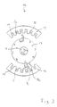
- the electrical machine 10 comprises two sector machines 15, 16, which act together on a runner 17.
- the sector machines 15, 16 are non-rotatably supported against the internal combustion engine 1, a vehicle chassis (not shown) or a (not shown) clutch housing, whereas the Runner 17 directly on the extension of the crankshaft 4 Internal combustion engine 1 sits and coupled to it in a rotationally fixed manner is.
- the extension of the crankshaft 4 and the rotor 17 rotate together, without interposing one Gearbox.
- the operation of the electrical machine 10 is illustrated in FIG. 3.
- the sector machines 15, 16 have three-phase windings 14 which, when subjected to three-phase current, form traveling fields with two poles each. There are three grooves 18 per pole, a total of 6 grooves 18 per sector machine 15, 16.
- the current position of the poles is illustrated with the reference symbols "S" (south pole) and "N" (north pole).
- the generation of radial forces on the shaft 4 illustrates the attractive force F 1 exerted by the north pole N 1 of the sector machine 15 on the south pole S 1 of the rotor 17, which can be broken down into a radial component F R1 and a tangential component F T1 .
- radial force F R1 radial vibrations of the shaft in the direction of the radial force F R1 can be counteracted directly.
- the south pole S 3 of the second sector machine 15 exerts a repulsive force with a tangential component F T2 on the south pole S 2 of the rotor 17.
- the electrical machine 10 can therefore apply radial forces in any direction to the shaft 4 and thus counteract radial vibrations in any direction.
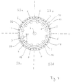
- Fig. 4 shows a further embodiment of an electrical Machine 10 for vibration damping. It includes a rotatably coupled to the extension of the crankshaft 4 Runner 17 and an outside, circular continuous stand 19 made of magnetically conductive material (here iron). The stand 19 comprises grooves 18 in the direction shaft 4.
- the electrical machine can be used as a synchronous or asynchronous machine.
- the inside Rotor 17 is in an asynchronous machine as a squirrel-cage rotor with cage bars running essentially in the axial direction, each with a short-circuit ring 20 are connected, trained.
- At the synchronous machine carries the runner 17 a corresponding number of poles as that Stand 19 (here twelve poles) by permanent magnets or magnetic coils fed via slip rings can.
- 4 shows the synchronous machine, by schematically indicating existing rotor poles 21 are.
- the stand 19 carries four independent windings 14, which each have a 90 ° sector 23 a, b, c, d of Stand 19 extend. These form with the application Three-phase current four hiking fields with three poles each out. There are three slots per pole, 18 in total per sector nine grooves 18 present. The current position of the poles is with the reference symbols "S" (for south pole) and "N" (for north pole) illustrated.
- the electrical machine 4 according to FIG. 4 thus corresponds Functionally four sector machines that work together on one Runner 17 act.
- the four three-phase windings 14 of the four Sectors 23 a, b, c, d are electrically independent. This is connected by four independent inverters (not shown here) reached.
- Everyone independent Sector 23a, b, c, d can, as in Fig. 3, for sector machines 15, 16 explains, apply radial forces to the shaft 4 and thus counteract radial vibrations.
- a sector machine in addition to radial forces (for example F R1 ), a sector machine also produces torque-causing forces (for example F T1 ). Therefore, in addition to radial vibrations, the electrical machine 10 according to FIG. 4 can also counteract torsional vibrations of the shaft 4, which are caused by the gas and mass forces of the engine 1.
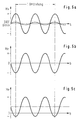
- 5a illustrates (with a solid line) the torque Mv of the internal combustion engine 1 as a function of the angle of rotation b of the crankshaft 2.
- the torque Me is a function of the shaft angle shown by the electrical machine 10 is applied.
- the course of this torque corresponds largely that of the engine torque Mv, but is opposite directed.
- the negative and positive torque extremes same size.
- the won during a braking phase So energy is essentially the same size as that of energy required in the following drive phase.
- the electrical machine 10 then also has the function of a generator, the current e.g. to compensate for operating losses of the system, for charging the vehicle battery 24 and can supply to operate electrical consumers.
- the torque Me of the electrical machine 10 can also 5c in the positive direction.
- the Electrical machine 10 then serves in addition to the reduction of radial or torsional vibrations as a (driving) motor, e.g. around the internal combustion engine 1 during vehicle acceleration to support.
- the electrical machine 10 thus fulfills several functions: on the one hand, it reduces radial and torsional vibrations the shaft 4, on the other hand it acts as a generator for Charge a vehicle battery 24 and thus replaces one alternator conventionally present in the motor vehicle.
- the generator function can also be used to brake the Serve vehicle or the internal combustion engine 1.
- the electrical machine as an additional motor (“booster") act, e.g. around the internal combustion engine 1 when accelerating to support the vehicle. It also serves as a starter for the internal combustion engine 1 and can therefore also conventionally provided separately in the motor vehicle Replace starter ("starter").
- starter motor vehicle Replace starter
- it acts due to the moment of inertia of the rotor 17 as Flywheel and can do so in conventional vehicles existing flywheel on the crankshaft replace.
- inverter 28 supplies one inverter 28 per active sector of the stand 19 or per sector machine 15, 16 at a high clock frequency (e.g. 100 Hz) voltage pulses freely selectable amplitude, frequency and phase (shown is only an inverter).
- a high clock frequency e.g. 100 Hz
- voltage pulses freely selectable amplitude, frequency and phase shown is only an inverter.
- a control device 27 passes through the inverter 28 appropriate control of its semiconductor switch each time before what amplitude, frequency and phase have the generated alternating voltages.
- the control device 27, for example, by an appropriately programmed Microcomputer system can be determined first the amount and direction of radial force and Torque, which the electrical machine 10 to a should generate a certain point in time. You can do this e.g. With Help map control by doing as input information Angular and radial position of shaft 4, the current one average speed and possibly other operating parameters, such as. receives the throttle valve position and from one stored map, the currently expected radial vibration and rotational nonuniformity depending on determined these operating parameters. Another possibility consists of actually existing radial vibrations and to determine rotational irregularities. Possible is also a combination of regulation and control.
- the Sensor 30 serves to measure radial deflection and speed two sensors 30 (only one sensor is shown).
- the Sensor 30 has a yoke-shaped shape around shaft 4 Ferrite core with alternating current windings on.
- the flux lines of the generated electromagnetic field emerge from one end of the ferrite core of sensor 30 and run into the shaft 4 through an air gap, emerge the shaft 4 and run over a further air gap in the other end of the ferrite core of the sensor 30 Wave 4 radial vibrations, the size of the changes Air gaps and thus the inductance of the sensor 30. From this can the current deflection and speed of the Shaft 4 can be determined in a radial direction.
- the second sensor serves in a different radial direction.
- a rotary transformer for measuring the rotational irregularities electrical machine 10 with a rotary transformer (so-called. Resolver) (not shown here). It exists from two adjacent printed circuit boards, one of which one is fixed and the other rotates with the shaft 4. The circuit boards bear on their facing surfaces turns formed by conductor tracks, such that a Angle-dependent transformer transformation ratio results.
- the rotary transformer works according to the transponder principle: The fixed turns (fixed Circuit board) are actively supplied with current / voltage and radiate electromagnetic energy to the rotatable turns (rotatable circuit board). The latter shine Part of this energy back again, being the reflection factor is dependent on the angle of rotation. The retroreflected part generates a rotation angle dependent in the fixed turns Signal. An evaluation of this signal provides the current angle of rotation of shaft 4 with an accuracy of at least 0.5 degrees.
- the target torque be determined based on stored values that the time course of the speed or torque specify the electrical machine 4 during the starting process, if necessary supplemented by a measurement of this Sizes and a feedback scheme that ensures compliance the requirements.
- control device 27 determines what amplitude, frequency and phase of the voltages or of the currents are provided by the inverters 28 need so that the electrical machine 10 the desired Exerts radial forces and torques.
- One and the same electrical machine 10 can therefore both Radial vibrations as well as torsional vibrations of shaft 4 counteract, the vibration damping over a wide frequency band can be made and degree of damping and Damping characteristics freely adjustable within wide limits are.
Landscapes
- Engineering & Computer Science (AREA)
- Mechanical Engineering (AREA)
- Transportation (AREA)
- Chemical & Material Sciences (AREA)
- Combustion & Propulsion (AREA)
- Power Engineering (AREA)
- General Engineering & Computer Science (AREA)
- Automation & Control Theory (AREA)
- Physics & Mathematics (AREA)
- Acoustics & Sound (AREA)
- Aviation & Aerospace Engineering (AREA)
- Life Sciences & Earth Sciences (AREA)
- Sustainable Energy (AREA)
- Sustainable Development (AREA)
- Electromagnetism (AREA)
- Electric Propulsion And Braking For Vehicles (AREA)
- Connection Of Motors, Electrical Generators, Mechanical Devices, And The Like (AREA)
- Hybrid Electric Vehicles (AREA)
- Control Of Vehicle Engines Or Engines For Specific Uses (AREA)
- Magnetic Bearings And Hydrostatic Bearings (AREA)
- Shafts, Cranks, Connecting Bars, And Related Bearings (AREA)
Abstract
Description
(Anspruch 1).
- es erlaubt eine sehr wirksame Unterdrückung der Dämpfung von Radial- und Drehschwingungen, insbesondere von Kurbelwellen;
- die Unterdrückung/Dämpfung kann über ein weites Frequenzband erfolgen;
- der Dämpfungsgrad und die Dämpfungscharakteristik sind in weiten Grenzen frei einstellbar;
- aufgrund der sehr wirksamen Schwingungsunterdrückung/dämpfung können hochbelastete Kurbelwellen mit geringerem Aufwand/zu geringeren Kosten geschaffen werden (nämlich aus weniger hochwertigem Material und mit geringerem Fertigungsaufwand) ;
- Fig. 1
- eine schematische Schnittdarstellung eines Systems zur aktiven Verringerung von Radialschwingungen mit einem Aktuator;
- Fig. 2
- eine unmaßstäblich-schematische Darstellung eines Systems zur aktiven Verringerung von Radialschwingungen mit einer elektrischen Maschine;
- Fig. 3
- eine schematische Schnittdarstellung der elektrischen Maschine, senkrecht zur Axialrichtung;
- Fig. 4
- eine schematische Schnittdarstellung einer zweiten Ausführungsform einer elektrischen Maschine, senkrecht zur Axialrichtung;
- Fig. 5
- eine schematische beispielhafte Darstellung der Funktionsweise der Schwingungsverringerung.
Claims (8)
- System zur aktiven Dämpfung von Schwingungen einer rotierenden Welle (4), insbesondere der Triebwelle eines Verbrennungsmotors (1), mittels einer elektrischen Maschine (10; 15, 16), welche zwei relativ zueinander drehbare elektromagnetische Wirkeinheiten (17, 19) aufweist, von denen eine mit der rotierenden Welle (4) verbunden ist und die andere gegen Drehung festgelegt oder - alternativ - mit einer anderen drehbaren Welle verbunden ist,
dadurch gekennzeichnet, daß
eine der Wirkeinheiten (19) wenigstens zwei elektrisch unabhängig ansteuerbare Wirksektoren (15, 16; 23a, 23b, 23c, 23d) zur Erzeugung von Wanderfeldern umfaßt, die jeweils auf die andere Wirkeinheit (17) Kräfte mit Radial- und Tangentialkomponenten (FR1, FR2, FT1, FT2) ausüben derart, daß in den wenigstens zwei Wirksektoren (15, 16; 23a, 23b, 23c, 23d) die Radialkomponenten (FR1, FR2) sich nicht aufheben zu einer ersten Radialkraft (FR3), und die Tangentialkomponenten (FT1, FT2) ein Drehmoment erzeugen, so daß die elektrische Maschine (10) sowohl Radial- als auch Drehschwingungen der Welle (4) dämpft, oder sich die Tangentialkomponenten (FT1, FT2) zu einer gegenüber der ersten Radialkraft (FR3) verschieden gerichteten, zweiten Radialkomponente (FT3) addieren, so daß die elektrische Maschine (10) Radialschwingungen der Welle (4) dämpft. - System nach Anspruch 1, bei welchem die unabhäng ansteuerbaren Wirksektoren voneinander gesonderte Wirksektoren (15, 16) sind.
- System nach Anspruch 1, bei welchem die unabhängig ansteuerbaren Wirksektoren (23 a,b,c,d) durch unabhängige Wicklungsabschnitte gebildet werden, die gemeinsam auf einem magnetisch leitenden Ständerkörper (19) angeordnet sind.
- System nach einem der vorhergehenden Ansprüche, bei welchem die elektrische Maschine (10; 15, 16) die Welle (4) außerdem mit einem antreibenden oder bremsenden Gleichdrehmoment beaufschlagen kann.
- System nach einem der vorhergehenden Ansprüche, bei welchem die elektrische Maschine (10; 15, 16) so ausgelegt ist, daß sie außerdem die Funktion eines Starters für den Verbrennungsmotor (1), eines Generators zur Stromversorgung, einer Fahrzeugbremse, einer Beschleunigungsunterstützung für das Fahrzeug hat.
- System nach einem der vorhergehenden Ansprüche, bei welchem die elektrische Maschine (10; 15, 16) so ausgelegt ist, daß sie zusätzlich als elektromagnetische Kupplung im Antriebsstrang und/oder als aktive Getriebesynchronisiereinrichtung wirkt.
- System nach einem der vorhergehenden Ansprüche, bei welchem die bei bremsender oder schlupfender Wirkung gewonnene Energie wenigstens teilweise gespeichert und wenigstens teilweise wiederverwendet wird.
- System nach einem der vorhergehenden Ansprüche, bei welchem die elektrische Maschine (10; 15, 16) von einem Wechselrichter (28) gesteuert wird, der diese zum Erzeugen der elektromagnetischen Felder mit Strömen und Spannungen variabler Amplitude, Frequenz und Phase versorgt.
Applications Claiming Priority (13)
| Application Number | Priority Date | Filing Date | Title |
|---|---|---|---|
| DE19532128A DE19532128A1 (de) | 1995-08-31 | 1995-08-31 | Antriebssystem, insbesondere für ein Kraftfahrzeug, und Verfahren zum Betreiben desselben |
| DE19532136 | 1995-08-31 | ||
| DE19532163 | 1995-08-31 | ||
| DE19532163A DE19532163A1 (de) | 1995-08-31 | 1995-08-31 | System zur aktiven Verringerung von Drehungleichförmigkeiten einer Welle, insbesondere der Triebwelle eines Verbrennungsmotors, und Verfahren hierzu |
| DE19532128 | 1995-08-31 | ||
| DE19532164 | 1995-08-31 | ||
| DE19532135A DE19532135A1 (de) | 1995-08-31 | 1995-08-31 | Antriebssystem, insbesondere für ein Kraftfahrzeug, und Verfahren zum Betreiben desselben |
| DE19532129 | 1995-08-31 | ||
| DE19532135 | 1995-08-31 | ||
| DE19532164A DE19532164A1 (de) | 1995-08-31 | 1995-08-31 | Antriebssystem, insbesondere für ein Kraftfahrzeug, und Verfahren zum Betreiben desselben |
| DE19532129A DE19532129A1 (de) | 1995-08-31 | 1995-08-31 | System zur aktiven Verringerung von Drehungleichförmigkeiten einer Welle, insbesondere der Triebwelle eines Verbrennungsmotors, und Verfahren hierzu |
| DE19532136A DE19532136A1 (de) | 1995-08-31 | 1995-08-31 | Antriebssystem, insbesondere für ein Kraftfahrzeug, und Verfahren zum Betreiben desselben |
| PCT/DE1996/001665 WO1997008477A2 (de) | 1995-08-31 | 1996-08-31 | System zur aktiven verringerung von radialschwingungen einer rotierenden welle sowie hierfür geeignete verfahren |
Publications (2)
| Publication Number | Publication Date |
|---|---|
| EP0845088A2 EP0845088A2 (de) | 1998-06-03 |
| EP0845088B1 true EP0845088B1 (de) | 2001-06-27 |
Family
ID=27545032
Family Applications (4)
| Application Number | Title | Priority Date | Filing Date |
|---|---|---|---|
| EP96937992A Expired - Lifetime EP0847490B1 (de) | 1995-08-31 | 1996-08-31 | Antriebssystem |
| EP96937185A Expired - Lifetime EP0847487B2 (de) | 1995-08-31 | 1996-08-31 | Antriebssystem mit antriebsmotor, elektrischer maschine und batterie |
| EP96937172A Expired - Lifetime EP0876554B2 (de) | 1995-08-31 | 1996-08-31 | Starter/generator für einen verbrennungsmotor, insbesondere eines kraftfahrzeugs |
| EP96937993A Expired - Lifetime EP0845088B1 (de) | 1995-08-31 | 1996-08-31 | System zur aktiven verringerung von radialschwingungen einer rotierenden welle sowie hierfür geeignete verfahren |
Family Applications Before (3)
| Application Number | Title | Priority Date | Filing Date |
|---|---|---|---|
| EP96937992A Expired - Lifetime EP0847490B1 (de) | 1995-08-31 | 1996-08-31 | Antriebssystem |
| EP96937185A Expired - Lifetime EP0847487B2 (de) | 1995-08-31 | 1996-08-31 | Antriebssystem mit antriebsmotor, elektrischer maschine und batterie |
| EP96937172A Expired - Lifetime EP0876554B2 (de) | 1995-08-31 | 1996-08-31 | Starter/generator für einen verbrennungsmotor, insbesondere eines kraftfahrzeugs |
Country Status (4)
| Country | Link |
|---|---|
| EP (4) | EP0847490B1 (de) |
| JP (1) | JP2002516057A (de) |
| DE (1) | DE59603588D1 (de) |
| WO (4) | WO1997008456A1 (de) |
Cited By (2)
| Publication number | Priority date | Publication date | Assignee | Title |
|---|---|---|---|---|
| DE102005001830A1 (de) * | 2005-01-14 | 2006-07-27 | Zf Friedrichshafen Ag | Verfahren zur Schwingungsdämpfung im Triebstrang eines ein Automatgetriebe umfassenden Kraftfahrzeugs |
| EP3994025B1 (de) * | 2019-07-04 | 2024-04-24 | Robert Bosch GmbH | Verfahren und vorrichtung zum betreiben einer antriebsanordnung eines kraftfahrzeugs, antriebsanordnung |
Families Citing this family (54)
| Publication number | Priority date | Publication date | Assignee | Title |
|---|---|---|---|---|
| EP0964996B1 (de) * | 1997-03-06 | 2003-02-26 | Continental ISAD Electronic Systems GmbH & Co. oHG | Starthilfsanlage für einen dieselmotor sowie verfahren zum starten eines dieselmotors |
| DE19709298C2 (de) | 1997-03-06 | 1999-03-11 | Isad Electronic Sys Gmbh & Co | Startersysteme für einen Verbrennungsmotor sowie Verfahren zum Starten eines Verbrennungsmotors |
| DE19752661C2 (de) † | 1997-11-27 | 2001-09-13 | Siemens Ag | Bordnetz für ein Kraftfahrzeug |
| DE19840819C1 (de) * | 1998-09-07 | 2000-08-03 | Isad Electronic Sys Gmbh & Co | Startersystem für einen Verbrennungsmotor sowie Verfahren zum Starten eines Verbrennungsmotors |
| GB9824099D0 (en) * | 1998-11-04 | 1998-12-30 | Rover Group | Vehicle traction control |
| DE19858348B4 (de) * | 1998-12-17 | 2004-04-15 | Continental Isad Electronic Systems Gmbh & Co. Ohg | Fahrzeug-Antriebssystem |
| DE19903272A1 (de) * | 1999-01-28 | 2000-08-03 | Bosch Gmbh Robert | Kraftstoffversorgungssystem für eine Brennkraftmaschine insbesondere eines Kraftfahrzeugs |
| GB2346351A (en) * | 1999-02-06 | 2000-08-09 | Rover Group | A motor vehicle having an electric motor for damping torque changes |
| DE19913656C1 (de) * | 1999-03-25 | 2001-01-18 | Isad Electronic Sys Gmbh & Co | Elektrische Maschine, insbesondere Starter/Generator für ein Kraftfahrzeug |
| GB2349483A (en) * | 1999-04-28 | 2000-11-01 | Rover Group | An engine-driven generator assembly |
| DE19950836A1 (de) * | 1999-10-21 | 2001-05-31 | Isad Electronic Sys Gmbh & Co | System mit einer elektrischen Maschine und einem Verbrennungsmotor, sowie elektrische Maschine, und Verfahren zur Abfuhr von Wärme aus einer elektrischen Maschine |
| DE19963400B4 (de) * | 1999-12-28 | 2010-06-10 | Robert Bosch Gmbh | Verfahren zur Steuerung eines Schaltvorganges in einem Antriebsaggregat für ein Kraftfahrzeug und Antriebsaggregat |
| GB2358845B (en) * | 2000-02-04 | 2002-03-13 | Michael Hawkins | Vehicle hybrid drive system and operating method |
| EP1186463A1 (de) * | 2000-08-28 | 2002-03-13 | Siemens Aktiengesellschaft | Verfahren zum Betrieb eines Antriebes mit einer Verbrennungsmaschine und einer elektrischen Maschine |
| SE516313C2 (sv) | 2000-09-07 | 2001-12-17 | Volvo Personvagnar Ab | Förfarande och anordning för styrning av ett drivssystem |
| DE10103520A1 (de) | 2001-01-26 | 2002-08-01 | Isad Electronic Sys Gmbh & Co | Generatorsystem, insbesondere für ein Kraftfahrzeug, sowie Verfahren zum Ansteuern eines Wechselrichters eines Asynchrongenerators |
| DE10103995A1 (de) * | 2001-01-30 | 2002-08-22 | Epcos Ag | Bordstromspeicher 12Volt und/oder 42Volt Kfz-Bordnetze sowie Vorrichtung zum Starten |
| JP3982247B2 (ja) * | 2001-12-06 | 2007-09-26 | 株式会社デンソー | 車両用発電機の制御装置 |
| DE10201601C1 (de) | 2002-01-16 | 2003-06-05 | Audi Hungaria Motor Kft | Verbrennungsmotor mit in einem Kurbelgehäuse gelagerter Kurbelwelle, wobei der Starter/Generator auf der Kurbelwelle angeordnet ist |
| JP3750608B2 (ja) * | 2002-01-23 | 2006-03-01 | トヨタ自動車株式会社 | 車両における蓄電装置の制御装置 |
| DE10204215A1 (de) | 2002-01-28 | 2003-08-21 | Bombardier Transp Gmbh | Fahrzeug mit Bremsenergiespeicher |
| DE10232327A1 (de) * | 2002-05-17 | 2003-11-27 | Daimler Chrysler Ag | Verfahren zum Betreiben einer Antriebseinheit für ein Kraftfahrzeug |
| JP4166753B2 (ja) | 2002-05-24 | 2008-10-15 | ダイムラー・アクチェンゲゼルシャフト | 内燃機関を有する自動車の電力供給のためのシステム |
| DE10231379B3 (de) | 2002-05-24 | 2004-01-15 | Daimlerchrysler Ag | Antriebssystem für ein Kraftfahrzeug mit einem Verbrennungsmotor und einer elektrischen Maschine |
| EP1401089A1 (de) | 2002-09-18 | 2004-03-24 | Continental ISAD Electronic Systems GmbH & Co. KG | Elektrische Maschine, ausgebildet als Starter, Generator oder Starter-Generator für ein Kraftfahrzeug |
| DE10248658B4 (de) * | 2002-10-18 | 2005-04-07 | Daimlerchrysler Ag | Vorrichtung zur Bordnetzstabilisierung bei Stopp/Startbetrieb |
| EP1422810A1 (de) | 2002-11-21 | 2004-05-26 | Continental ISAD Electronic Systems GmbH & Co. oHG | Kraftfahrzeug-Antriebssystem |
| US6769389B2 (en) * | 2002-11-26 | 2004-08-03 | General Motors Corporation | Dual voltage tandem engine start system and method |
| EP1424494A1 (de) | 2002-11-27 | 2004-06-02 | Continental ISAD Electronic Systems GmbH & Co. oHG | Hybridantriebssystem sowie Verfahren zur gemeinsamen Aufbringung von Antriebs-Drehmoment |
| FR2836763A1 (fr) * | 2003-03-19 | 2003-09-05 | Valeo Equip Electr Moteur | Procede de commande d'une machine electrique tournante et reversible pour vehicule automobile a moteur thermique |
| US7279855B2 (en) * | 2003-04-04 | 2007-10-09 | Hitachi, Ltd. | Electric drive device for vehicle and hybrid engine/motor-type four wheel drive device |
| AT414299B (de) * | 2003-06-25 | 2006-12-15 | Rosenbauer Int Ag | Antriebssystem, sowie verfahren zur steuerung eines antriebssystems |
| DE10335348B4 (de) * | 2003-08-01 | 2006-02-16 | Temic Automotive Electric Motors Gmbh | Elektrische Leitungsdurchführung |
| EP1669236B1 (de) * | 2003-09-11 | 2018-08-29 | Nissan Diesel Motor Co., Ltd. | Gangschaltsteuervorrichtung für hybrid-elektro-fahrzeug |
| FR2877057A1 (fr) * | 2004-10-22 | 2006-04-28 | Peugeot Citroen Automobiles Sa | Moteur thermique a machine electrique integree au vilebrequin. |
| EP1666321A1 (de) * | 2004-12-06 | 2006-06-07 | Ford Global Technologies, LLC, A subsidary of Ford Motor Company | Verfahren zum Bremsen eines Fahrzeugs, Bremsvorrichtung und Fahrzeug mit einer Bremsvorrichtung |
| DE102005007966A1 (de) * | 2005-02-22 | 2006-10-05 | Zf Friedrichshafen Ag | Antriebsstrang eines Kraftfahrzeugs und Verfahren zum Betreiben des Antriebsstranges |
| DE102006044138A1 (de) | 2006-09-15 | 2008-03-27 | Siemens Ag | Energiespeichersystem für ein Kraftfahrzeug und Verfahren zum Steuern eines Energiespeichersystems |
| DE102007003756A1 (de) * | 2007-01-19 | 2008-07-31 | Fev Motorentechnik Gmbh | Verfahren zum dynamischen Ausgleich eines zeitlich schwankenden Drehmomentangebots |
| DE102008040489A1 (de) * | 2008-07-17 | 2010-01-21 | Zf Friedrichshafen Ag | Brennkraftmaschine-Hybridgetriebe-Verbund |
| FR2945081B1 (fr) * | 2009-04-29 | 2011-04-29 | Peugeot Citroen Automobiles Sa | Procede et systeme d'arret et de redemarrage automatique d'un moteur thermique |
| RU2010151860A (ru) | 2009-12-22 | 2012-06-27 | Ес Пауер А/С (Dk) | Генератор, двигатель-генератор и способ изготовления двигателя-генератора |
| DE102010043095A1 (de) | 2010-10-29 | 2012-05-03 | Robert Bosch Gmbh | Verfahren zur Reduzierung einer Spannungswelligkeit aufgrund Drehungleichförmigkeit eines von einer Brennkraftmaschine angetriebenen Generators |
| DE102012203778A1 (de) | 2011-04-04 | 2012-10-04 | Schaeffler Technologies AG & Co. KG | Verfahren zur Steuerung eines hybridischen Antriebsstrangs und Akkumulatoreinrichtung in diesem |
| DE102011101386B4 (de) * | 2011-05-12 | 2021-12-16 | Bayerische Motoren Werke Aktiengesellschaft | Vorrichtung zum Reduzieren von Drehungleichförmigkeiten |
| US8779622B2 (en) | 2011-06-30 | 2014-07-15 | GM Global Technology Operations LLC | Customizable energy system and vehicle |
| JP5567608B2 (ja) * | 2012-02-10 | 2014-08-06 | ニチユ三菱フォークリフト株式会社 | 産業用車両 |
| DE102012024551A1 (de) | 2012-12-17 | 2014-06-18 | Fev Gmbh | Generatorsteuerung für ruhigen Betrieb mit Verbrennungsmotor |
| CN105189174B (zh) * | 2013-03-05 | 2018-01-26 | 西门子公司 | 具有在曲轴处的电驱动装置的内燃机 |
| DE102013102493A1 (de) * | 2013-03-12 | 2014-09-18 | Harald Breitbach | Verfahren und Vorrichtung zum Abmindern von Drehschwingungen eines Rotors |
| FR3051031B1 (fr) | 2016-05-09 | 2020-01-24 | Renault S.A.S. | Dispositif de synchronisation d'un pignon sur un arbre de boite de vitesses en mode regeneratif, procede et vehicule automobile correspondants |
| FR3068838B1 (fr) * | 2017-07-07 | 2020-10-09 | Continental Automotive France | Regulation du rendement electrique et du couple de freinage associe d'une machine electrique |
| DE102022110509A1 (de) | 2022-04-29 | 2023-11-02 | Volkswagen Aktiengesellschaft | Verfahren zur Reduzierung von Emissionen einer Brennkraftmaschine bei Kaltabfahrt |
| DE102022206683A1 (de) | 2022-06-30 | 2024-01-04 | Siemens Mobility GmbH | Elektrisches Antriebssystem für ein Schienenfahrzeug |
Family Cites Families (34)
| Publication number | Priority date | Publication date | Assignee | Title |
|---|---|---|---|---|
| US3774303A (en) * | 1966-02-25 | 1973-11-27 | Chain saw starting system | |
| SE7409754L (de) * | 1974-01-18 | 1975-07-21 | Walter Schonball | |
| US3902073A (en) * | 1974-02-07 | 1975-08-26 | Gen Electric | Starter generator electrical system utilizing phase controlled rectifiers to drive a dynamoelectric machine as a brushless dc motor in the starter mode and to provide frequency conversion for a constant frequency output in the generating mode |
| JPS50158014A (de) * | 1974-06-10 | 1975-12-20 | ||
| DE2434253A1 (de) * | 1974-07-17 | 1976-01-29 | Gerhard Dipl Ing Hagedorn | Kraftwagenantrieb mittels verbrennungsund elektromotor |
| JPS5132926A (en) * | 1974-09-14 | 1976-03-19 | Kogyo Gijutsuin | Fukusudenchi no haiburitsudoseigyohoshiki |
| JPS58126434A (ja) * | 1982-01-23 | 1983-07-27 | Nissan Motor Co Ltd | 内燃機関のトルク平滑化装置 |
| FR2563280B1 (fr) * | 1984-04-20 | 1988-12-09 | Jeumont Schneider | Vehicule automobile et procede de commande du moteur de ce vehicule, permettant de reduire la consommation en carburant et la pollution |
| US4699097A (en) * | 1984-08-31 | 1987-10-13 | Mazda Motor Corporation | Means for suppressing engine output torque fluctuations |
| JPS62166749A (ja) * | 1986-01-14 | 1987-07-23 | Fanuc Ltd | 電動機 |
| GB8603590D0 (en) * | 1986-02-13 | 1986-03-19 | Lucas Ind Plc | Dynamo electric machines |
| FR2604041B1 (fr) * | 1986-09-11 | 1988-10-28 | Valeo | Procede de commande d'une machine electrique reversible generateur-moteur, pour vehicule automobile, et installation de commande pour la mise en oeuvre d'un tel procede |
| JP2539221B2 (ja) * | 1987-06-10 | 1996-10-02 | マツダ株式会社 | エンジンの始動充電装置 |
| JPH01113571A (ja) * | 1987-10-27 | 1989-05-02 | Mazda Motor Corp | エンジンのトルク変動低減装置 |
| DE3743317A1 (de) * | 1987-12-21 | 1989-06-29 | Bosch Gmbh Robert | Fahrzeugbordnetzsystem |
| JPH01190922A (ja) * | 1988-01-27 | 1989-08-01 | Hitachi Ltd | 内燃機関のトルク制御装置 |
| US4883973A (en) * | 1988-08-01 | 1989-11-28 | General Motors Corporation | Automotive electrical system having a starter/generator induction machine |
| JPH0691759B2 (ja) * | 1988-08-12 | 1994-11-14 | 株式会社日立製作所 | 内燃機関の発電制御装置 |
| US5125236A (en) * | 1989-09-15 | 1992-06-30 | Onan Corporation | Combined generator set and air conditioning compressor drive system |
| JPH0734678B2 (ja) * | 1989-11-09 | 1995-04-12 | いすゞ自動車株式会社 | アイドル振動低減装置 |
| SE467422B (sv) * | 1990-04-23 | 1992-07-13 | Volvo Ab | Anordning foer att saekerstaella start av en foerbraenningsmotor |
| EP0557522B1 (de) * | 1990-10-29 | 1996-02-07 | Yuasa Corporation | Wasserstoff-speicherelektrode, nickelelektrode und nickel-wasserstoffbatterie |
| US5126641A (en) * | 1991-03-08 | 1992-06-30 | Westinghouse Electric Corp. | Bidirectional variable reluctance actuator and system for active attenuation of vibration and structure borne noise utilizing same |
| JPH05211258A (ja) * | 1991-07-31 | 1993-08-20 | Hitachi Ltd | 沸騰冷却装置 |
| EP0530659B1 (de) * | 1991-08-29 | 1997-11-05 | The Furukawa Electric Co., Ltd. | Verfahren zur Herstellung einer Elektrode aus wasserstoffspeichernder Legierung |
| AT398188B (de) * | 1992-05-05 | 1994-10-25 | Laimboeck Franz | Antriebsvorrichtung für ein kraftfahrzeug |
| JP3314484B2 (ja) * | 1992-12-28 | 2002-08-12 | 株式会社デンソー | 車両制振装置 |
| US5325042A (en) * | 1993-01-29 | 1994-06-28 | Allied Signal Inc. | Turbine engine start system with improved starting characteristics |
| JP3131671B2 (ja) * | 1993-02-22 | 2001-02-05 | 悟 深田 | 磁気軸受装置 |
| WO1995002758A1 (en) * | 1993-07-15 | 1995-01-26 | Onan Corporation | Auxiliary power system for hybrid electric vehicle |
| JPH07105943A (ja) * | 1993-10-06 | 1995-04-21 | Sanyo Electric Co Ltd | 水素吸蔵合金電極 |
| US5359308A (en) * | 1993-10-27 | 1994-10-25 | Ael Defense Corp. | Vehicle energy management system using superconducting magnetic energy storage |
| DE4423577C2 (de) * | 1994-02-28 | 1996-07-18 | Clouth Gummiwerke Ag | Aktives Schwingungsdämpfungungssystem |
| JP3516361B2 (ja) * | 1995-01-17 | 2004-04-05 | 富士重工業株式会社 | 車両用電源装置 |
-
1996
- 1996-08-31 WO PCT/DE1996/001622 patent/WO1997008456A1/de not_active Ceased
- 1996-08-31 WO PCT/DE1996/001663 patent/WO1997008439A1/de not_active Ceased
- 1996-08-31 EP EP96937992A patent/EP0847490B1/de not_active Expired - Lifetime
- 1996-08-31 DE DE59603588T patent/DE59603588D1/de not_active Expired - Lifetime
- 1996-08-31 WO PCT/DE1996/001664 patent/WO1997008440A1/de not_active Ceased
- 1996-08-31 JP JP50972297A patent/JP2002516057A/ja active Pending
- 1996-08-31 EP EP96937185A patent/EP0847487B2/de not_active Expired - Lifetime
- 1996-08-31 EP EP96937172A patent/EP0876554B2/de not_active Expired - Lifetime
- 1996-08-31 WO PCT/DE1996/001665 patent/WO1997008477A2/de not_active Ceased
- 1996-08-31 EP EP96937993A patent/EP0845088B1/de not_active Expired - Lifetime
Cited By (3)
| Publication number | Priority date | Publication date | Assignee | Title |
|---|---|---|---|---|
| DE102005001830A1 (de) * | 2005-01-14 | 2006-07-27 | Zf Friedrichshafen Ag | Verfahren zur Schwingungsdämpfung im Triebstrang eines ein Automatgetriebe umfassenden Kraftfahrzeugs |
| DE102005001830B4 (de) * | 2005-01-14 | 2010-05-12 | Zf Friedrichshafen Ag | Verfahren zur Schwingungsdämpfung im Triebstrang eines ein Automatgetriebe umfassenden Kraftfahrzeugs |
| EP3994025B1 (de) * | 2019-07-04 | 2024-04-24 | Robert Bosch GmbH | Verfahren und vorrichtung zum betreiben einer antriebsanordnung eines kraftfahrzeugs, antriebsanordnung |
Also Published As
| Publication number | Publication date |
|---|---|
| EP0876554B1 (de) | 2000-11-02 |
| EP0847487B1 (de) | 1999-11-03 |
| JP2002516057A (ja) | 2002-05-28 |
| EP0876554B2 (de) | 2007-01-24 |
| WO1997008477A3 (de) | 1997-08-14 |
| EP0847490B1 (de) | 1999-11-10 |
| EP0847487A1 (de) | 1998-06-17 |
| WO1997008440A1 (de) | 1997-03-06 |
| EP0847490A1 (de) | 1998-06-17 |
| WO1997008439A1 (de) | 1997-03-06 |
| EP0845088A2 (de) | 1998-06-03 |
| DE59603588D1 (de) | 1999-12-09 |
| EP0847487B2 (de) | 2004-10-20 |
| WO1997008477A2 (de) | 1997-03-06 |
| EP0876554A1 (de) | 1998-11-11 |
| WO1997008456A1 (de) | 1997-03-06 |
Similar Documents
| Publication | Publication Date | Title |
|---|---|---|
| EP0845088A2 (de) | System zur aktiven verringerung von radialschwingungen einer rotierenden welle sowie hierfür geeignete verfahren | |
| EP0847489B1 (de) | System zur aktiven verringerung von drehungleichförmigkeiten einer welle, insbesondere der triebwelle eines verbrennungsmotors, und verfahren hierzu | |
| DE19631384C1 (de) | Elektrische Maschine in einem Antriebsstrang, z. B. eines Kraftfahrzeuges | |
| EP0847486B1 (de) | Antriebssystem, insbesondere für ein kraftfahrzeug | |
| DE4447537B4 (de) | Verfahren und System zur aktiven Schwingungsdämpfung | |
| EP1634368B1 (de) | Verfahren und dämpfungsvorrichtung zur dämpfung einer torsionsschwingung in einem rotierenden antriebsstrang | |
| EP0847488B1 (de) | Antriebssystem, insbesondere für ein kraftfahrzeug | |
| EP0847485B1 (de) | System zur aktiven dämpfung von drehungleichförmigkeiten der kurbelwelle eines verbrennungsmotors oder einer damit gekoppelten welle. | |
| DE4423577C2 (de) | Aktives Schwingungsdämpfungungssystem | |
| EP0861162B1 (de) | Motorfahrzeug mit elektrischem generator | |
| WO2022188926A1 (de) | Elektrische maschine, verfahren zur steuerung einer elektrischen maschine, computerprogrammprodukt und steuereinheit | |
| DE19727507A1 (de) | Regelung für einen Antrieb mit einem Asynchronmotor | |
| EP0846065B1 (de) | Antriebsschlupfsteuerungssystem für ein kraftfahrzeug unter verwendung einer elektrischen maschine | |
| DE10326816A1 (de) | Verfahren und Dämpfungsvorrichtung zur Dämpfung einer Torsionsschwingung in einem rotierenden Antriebsstrang | |
| DE102021124534A1 (de) | Elektrische Maschine, Verfahren zur Steuerung einer elektrischen Maschine, Computerprogrammprodukt und Steuereinheit | |
| DE4218888A1 (de) | Elektrische Maschine | |
| DE102004027529B4 (de) | Verfahren und Vorrichtung zur Tilgung von Drehschwingungen und Drehungleichförmigkeiten für Antriebsstränge | |
| EP3724989B1 (de) | Betreiben eines ladereglers für einen elektrischen speicher in einem kraftfahrzeug | |
| DE4447574B4 (de) | Verfahren zur aktiven Schwingungsdämpfung und ein System zu dessen Durchführung | |
| EP0965007A2 (de) | Vorrichtung zur verringerung von drehungleichförmigkeiten und verfahren hierzu | |
| DE2544726C2 (de) | Störkomponentenunterdrückung bei der magnetischen Radiallagerung eines Rotors | |
| DE10359259A1 (de) | Verfahren und Dämpfungsvorrichtung zur Dämpfung einer Torsionsschwingung in einem rotierenden Antriebsstrang | |
| DE102021126143A1 (de) | Elektrische Axialflussmaschine |
Legal Events
| Date | Code | Title | Description |
|---|---|---|---|
| PUAI | Public reference made under article 153(3) epc to a published international application that has entered the european phase |
Free format text: ORIGINAL CODE: 0009012 |
|
| 17P | Request for examination filed |
Effective date: 19980327 |
|
| AK | Designated contracting states |
Kind code of ref document: A2 Designated state(s): DE FR GB IT |
|
| 17Q | First examination report despatched |
Effective date: 19980904 |
|
| RAP1 | Party data changed (applicant data changed or rights of an application transferred) |
Owner name: GRUENDL UND HOFFMANN GMBH GESELLSCHAFT FUER ELEKT Owner name: CONTINENTAL ISAD ELECTRONIC SYSTEMS GMBH & CO. KG |
|
| GRAG | Despatch of communication of intention to grant |
Free format text: ORIGINAL CODE: EPIDOS AGRA |
|
| GRAG | Despatch of communication of intention to grant |
Free format text: ORIGINAL CODE: EPIDOS AGRA |
|
| GRAH | Despatch of communication of intention to grant a patent |
Free format text: ORIGINAL CODE: EPIDOS IGRA |
|
| RAP1 | Party data changed (applicant data changed or rights of an application transferred) |
Owner name: CONTINENTAL ISAD ELECTRONIC SYSTEMS GMBH & CO. OHG |
|
| GRAH | Despatch of communication of intention to grant a patent |
Free format text: ORIGINAL CODE: EPIDOS IGRA |
|
| GRAA | (expected) grant |
Free format text: ORIGINAL CODE: 0009210 |
|
| AK | Designated contracting states |
Kind code of ref document: B1 Designated state(s): DE FR GB IT |
|
| GBT | Gb: translation of ep patent filed (gb section 77(6)(a)/1977) |
Effective date: 20010629 |
|
| REF | Corresponds to: |
Ref document number: 59607178 Country of ref document: DE Date of ref document: 20010802 |
|
| ITF | It: translation for a ep patent filed | ||
| ET | Fr: translation filed | ||
| REG | Reference to a national code |
Ref country code: GB Ref legal event code: IF02 |
|
| PLBE | No opposition filed within time limit |
Free format text: ORIGINAL CODE: 0009261 |
|
| STAA | Information on the status of an ep patent application or granted ep patent |
Free format text: STATUS: NO OPPOSITION FILED WITHIN TIME LIMIT |
|
| 26N | No opposition filed | ||
| PGFP | Annual fee paid to national office [announced via postgrant information from national office to epo] |
Ref country code: GB Payment date: 20040730 Year of fee payment: 9 |
|
| PGFP | Annual fee paid to national office [announced via postgrant information from national office to epo] |
Ref country code: FR Payment date: 20040809 Year of fee payment: 9 |
|
| PGFP | Annual fee paid to national office [announced via postgrant information from national office to epo] |
Ref country code: DE Payment date: 20050812 Year of fee payment: 10 |
|
| PG25 | Lapsed in a contracting state [announced via postgrant information from national office to epo] |
Ref country code: IT Free format text: LAPSE BECAUSE OF NON-PAYMENT OF DUE FEES;WARNING: LAPSES OF ITALIAN PATENTS WITH EFFECTIVE DATE BEFORE 2007 MAY HAVE OCCURRED AT ANY TIME BEFORE 2007. THE CORRECT EFFECTIVE DATE MAY BE DIFFERENT FROM THE ONE RECORDED. Effective date: 20050831 Ref country code: GB Free format text: LAPSE BECAUSE OF NON-PAYMENT OF DUE FEES Effective date: 20050831 |
|
| GBPC | Gb: european patent ceased through non-payment of renewal fee |
Effective date: 20050831 |
|
| PG25 | Lapsed in a contracting state [announced via postgrant information from national office to epo] |
Ref country code: FR Free format text: LAPSE BECAUSE OF NON-PAYMENT OF DUE FEES Effective date: 20060428 |
|
| REG | Reference to a national code |
Ref country code: FR Ref legal event code: ST Effective date: 20060428 |
|
| PG25 | Lapsed in a contracting state [announced via postgrant information from national office to epo] |
Ref country code: DE Free format text: LAPSE BECAUSE OF NON-PAYMENT OF DUE FEES Effective date: 20070301 |