EP0845322A1 - Plasmabrenner - Google Patents
Plasmabrenner Download PDFInfo
- Publication number
- EP0845322A1 EP0845322A1 EP96923084A EP96923084A EP0845322A1 EP 0845322 A1 EP0845322 A1 EP 0845322A1 EP 96923084 A EP96923084 A EP 96923084A EP 96923084 A EP96923084 A EP 96923084A EP 0845322 A1 EP0845322 A1 EP 0845322A1
- Authority
- EP
- European Patent Office
- Prior art keywords
- workpiece
- torch
- plasma torch
- plasma
- contact
- Prior art date
- Legal status (The legal status is an assumption and is not a legal conclusion. Google has not performed a legal analysis and makes no representation as to the accuracy of the status listed.)
- Withdrawn
Links
- 238000011010 flushing procedure Methods 0.000 claims abstract description 5
- 239000004020 conductor Substances 0.000 claims description 10
- 230000006872 improvement Effects 0.000 claims description 6
- 230000002159 abnormal effect Effects 0.000 abstract description 20
- 239000007769 metal material Substances 0.000 abstract description 7
- 230000014759 maintenance of location Effects 0.000 description 15
- 239000003990 capacitor Substances 0.000 description 8
- 238000003466 welding Methods 0.000 description 8
- 238000010276 construction Methods 0.000 description 7
- 230000015556 catabolic process Effects 0.000 description 6
- 238000005520 cutting process Methods 0.000 description 5
- 238000010586 diagram Methods 0.000 description 5
- 238000000034 method Methods 0.000 description 5
- 230000000694 effects Effects 0.000 description 4
- 238000002474 experimental method Methods 0.000 description 4
- 239000000463 material Substances 0.000 description 4
- 230000007246 mechanism Effects 0.000 description 4
- 230000008569 process Effects 0.000 description 4
- RYGMFSIKBFXOCR-UHFFFAOYSA-N Copper Chemical compound [Cu] RYGMFSIKBFXOCR-UHFFFAOYSA-N 0.000 description 3
- 239000000919 ceramic Substances 0.000 description 3
- 229910052802 copper Inorganic materials 0.000 description 3
- 239000010949 copper Substances 0.000 description 3
- 238000011161 development Methods 0.000 description 3
- 238000012856 packing Methods 0.000 description 3
- XLYOFNOQVPJJNP-UHFFFAOYSA-N water Substances O XLYOFNOQVPJJNP-UHFFFAOYSA-N 0.000 description 3
- 239000003779 heat-resistant material Substances 0.000 description 2
- 238000004904 shortening Methods 0.000 description 2
- 230000007306 turnover Effects 0.000 description 2
- 230000015572 biosynthetic process Effects 0.000 description 1
- 229910010293 ceramic material Inorganic materials 0.000 description 1
- 230000008878 coupling Effects 0.000 description 1
- 238000010168 coupling process Methods 0.000 description 1
- 238000005859 coupling reaction Methods 0.000 description 1
- 230000002950 deficient Effects 0.000 description 1
- 230000002542 deteriorative effect Effects 0.000 description 1
- 239000012777 electrically insulating material Substances 0.000 description 1
- 239000011810 insulating material Substances 0.000 description 1
- 238000011835 investigation Methods 0.000 description 1
- 230000009191 jumping Effects 0.000 description 1
- 239000002184 metal Substances 0.000 description 1
- 229910052751 metal Inorganic materials 0.000 description 1
- 230000000135 prohibitive effect Effects 0.000 description 1
- 230000002035 prolonged effect Effects 0.000 description 1
- 230000001681 protective effect Effects 0.000 description 1
- 230000009467 reduction Effects 0.000 description 1
- 238000009877 rendering Methods 0.000 description 1
- 238000011160 research Methods 0.000 description 1
- 230000000630 rising effect Effects 0.000 description 1
- 239000000126 substance Substances 0.000 description 1
- 238000012546 transfer Methods 0.000 description 1
- 238000004804 winding Methods 0.000 description 1
Images

Classifications
-
- H—ELECTRICITY
- H05—ELECTRIC TECHNIQUES NOT OTHERWISE PROVIDED FOR
- H05H—PLASMA TECHNIQUE; PRODUCTION OF ACCELERATED ELECTRICALLY-CHARGED PARTICLES OR OF NEUTRONS; PRODUCTION OR ACCELERATION OF NEUTRAL MOLECULAR OR ATOMIC BEAMS
- H05H1/00—Generating plasma; Handling plasma
- H05H1/24—Generating plasma
- H05H1/26—Plasma torches
- H05H1/32—Plasma torches using an arc
- H05H1/34—Details, e.g. electrodes, nozzles
- H05H1/3478—Geometrical details
-
- H—ELECTRICITY
- H05—ELECTRIC TECHNIQUES NOT OTHERWISE PROVIDED FOR
- H05H—PLASMA TECHNIQUE; PRODUCTION OF ACCELERATED ELECTRICALLY-CHARGED PARTICLES OR OF NEUTRONS; PRODUCTION OR ACCELERATION OF NEUTRAL MOLECULAR OR ATOMIC BEAMS
- H05H1/00—Generating plasma; Handling plasma
- H05H1/24—Generating plasma
- H05H1/26—Plasma torches
- H05H1/32—Plasma torches using an arc
- H05H1/34—Details, e.g. electrodes, nozzles
-
- H—ELECTRICITY
- H05—ELECTRIC TECHNIQUES NOT OTHERWISE PROVIDED FOR
- H05H—PLASMA TECHNIQUE; PRODUCTION OF ACCELERATED ELECTRICALLY-CHARGED PARTICLES OR OF NEUTRONS; PRODUCTION OR ACCELERATION OF NEUTRAL MOLECULAR OR ATOMIC BEAMS
- H05H1/00—Generating plasma; Handling plasma
- H05H1/24—Generating plasma
- H05H1/26—Plasma torches
- H05H1/32—Plasma torches using an arc
- H05H1/34—Details, e.g. electrodes, nozzles
- H05H1/36—Circuit arrangements
Definitions
- the present invention relates to a plasma torch that is designed to effect a welding or a cutting operation for a workpiece while bringing a portion of the plasma torch in contact with the workpiece.
- a plasma torch In a plasma welding or process, where the resulting weld or cut quality is of a prime importance, it has been known to be necessary to perform the operation with a plasma torch while maintaining the distance between a nozzle forward end thereof and a workpiece, i. e. a standoff, constant.
- a plasma torch has typically been employed having a member that is mounted to a body portion thereof and designed to surround a nozzle forward end thereof, and such a plasma torch has been configured in a construction as disclosed in Japanese Examined Patent Publication No. Hei 3-9902 and Japanese Unexamined Patent Publication No. Hei 7-16752 in the prior art.
- a spring member composed of a material having a heat resistant property is externally provided on the body of the plasma torch to form a coiled spring thereon whose leg end, extending downwards beyond the torch forward end, can be urged to engage with a workpiece so as to cut the workpiece.
- the end of a retention cap mounted to the torch end extends downwards beyond the torch forward end and is urged to engage with a workpiece so as to spot weld the workpiece with another workpiece.
- the contacting member is composed especially of a metal, such as copper, having a high thermal conductivity
- the member that is naturally of a non-insulating body allows a high frequency electric current that may be brought about when a plasma arc is started to leak therethrough into the workpiece, thus giving rise to a problem such as tending to develop an abnormal discharge or to make a plasma arc hard to develop.
- a plasma torch as disclosed in the above mentioned utility model publication, No. Hei 2-39657 makes use of a packing interposed between the end of a torch body portion of the plasma torch and the end of an insulating cap disposed to coaxially surround a nozzle portion of the plasma torch with a spacing that is traversed by a shielding gas, where the packing is composed of an electrically insulating and heat resistant material such as to prevent a high frequency current from leaking from a region of the plasma torch into a region of the workpiece, and hence to prevent a development of any abnormal discharge.
- the cap be composed of a metallic material that is good in thermal conduction and yet be cooled by water while the operation is being performed. Yet with such, a measure, however, it has been found that the problem of a high frequency current leaking via the metallic cap into the region of a workpiece and hence the problems of development of an abnormal discharge and failure for an arc plasma to ignite may still be encountered.
- a plasma arc with a plasma torch can be started with an arc current of low amperage, commonly referred to as "pilot arc", that is initially produced between an electrode and a torch nozzle of the plasma torch, the pilot arc being then allowed to reach a workpiece and thence to shift into a main arc that is produced between the electrode and the workpiece.
- pilot arc an arc current of low amperage
- the main arc is called "plasma arc" because of its nature, and is characterized by an extremely elevated energy density and a high arc directivity.
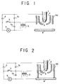
- a pilot arc when a pilot arc is started, it will be required for a high frequency (HF) power with an extremely high voltage generated by a HF power supply (not shown) to be applied to the primary winding of a HF generator 5, to establish a resonant circuit which is formed by the HF generator 5, a capacitor 7a, the electrode 1, the torch nozzle 2 and the transformer 5 that are connected in series, thereby allowing an elevated voltage HF current to be applied across the electrode 1 and the torch nozzle 2, thus permitting the dielectric space 6 to be broken down, thereto establish a circuit for a pilot arc.
- HF high frequency
- a main arc circuit which is formed by the DC power supply 4, an ammeter 9, the workpiece 8, the electrode 1 and the DC power supply 4 that are connected in series.
- the ammeter 9 is operative to detect a current that is indicative of the formation of this main arc circuit. Therefore the switch 3 is turned off thereafter, thereby rendering the above mentioned pilot arc circuit in an open condition to extinguish any pilot arc and to allow it to shift into a main arc.
- a second capacitor 7b is provided to isolate the HF current from the DC power supply 4 and the nozzle cap is indicated at 10a.
- Fig. 1 shows an example of circuit construction in which the HF generator 5 is connected to the torch nozzle 2
- the HF generator 5 may alternatively be connected to the electrode 1 as shown in Fig. 3.
- the mechanism for arc generation in the Fig. 1 example as discussed in connection therewith equally applies to the latter example as well.
- a standoff retention contact type cap 10b of the plasma torch of the type described if composed of a ceramic or the like material on account of its required heat resistant property, leaves much to be desired as to the reliability, the running cost and so forth of a working operation. Note particularly that a ceramic is highly expensive and its utilization in such a manner may render the running cost of a process even prohibitive.
- the standoff retention contact type cap 10b be composed of a metallic material having a high thermal conductivity. If so composed, the standoff retention contact type cap 10b will be placed at a same potential as the workpiece 8 and when the HF power supply is allowed to start its operation, it follows that the first circuit which is constituted by the electrode 1 - the capacitor 7a - the HF generator 5 - the torch coil 2 - the dielectric space 6 - the electrode 1 in series and the second circuit which is constituted by the standoff retention contact type cap 10b - the workpiece 8 - the capacitor 7b - the HF generator 5 - the torch nozzle 2 - a second dielectric space 11 - the standoff retention contact type cap 10b in series will be made structurally and functionally equivalent to each other as a whole.
- the impedance provided by the conductor here, the self-inductance provided by the conductor with the power supply being an HF power supply
- the impedance provided by the conductor will be increased, thus causing a delay in charge passage in the torch nozzle 2, then possibly permitting a discharge to occur jumping from the torch nozzle 2 to the standoff retention contact type cap 10b to allow electric charges to transfer (a current to be passed) in the latter circuit mentioned above.
- a plasma torch for performing a working operation with respect to a workpiece by flushing a plasma arc drawn from an electrode, together with a working gas introduced from around the electrode, from a torch nozzle against the workpiece while holding a portion of the plasma torch substantially in contact therewith, in which that a portion of the plasma torch which makes a contact with the workpiece can be composed of a metallic material which is high in thermal conductivity and that a high frequency electric current is prevented from leaking from the plasma torch into a region of the workpiece and an arc may not fail to be ignited.
- a plasma torch for performing a working operation with respect to a workpiece by flushing out of a torch nozzle, a plasma arc drawn from an electrode together with a working gas that is introduced from a periphery of the electrode while holding a portion of the plasma torch substantially in contact with the workpiece, the improvement in which at least that portion of the said plasma torch which may make a contact with the workpiece is composed of a non-insulating member and in which a high frequency current bypassing means is disposed between a site of the plasma torch that is equal in electric potential to the torch nozzle and a site of the plasma torch that is equal in electric potential to the workpiece.
- the said HF current bypassing means be disposed between said torch nozzle and a torch constituting member which is in contact with the workpiece and equal in electric potential to the workpiece, and be mounted to the said torch as associated with a body portion thereof, and that there be provided a conductor having a length less than 5 m for connecting the said HF current bypassing means in an electrical circuit and having a length less than 3 mm for connecting the plasma torch to a direct current power supply.
- the present inventors used as the HF current bypassing means a bypassing filter 12 with a capacitor as shown in Fig. 5 and incorporated it between the torch nozzle 2 and a standoff retention contact type cap 11b composed of a metallic material high in thermal conductivity and disposed in contact with and being equal in electric potential to the workpiece 8.
- bypassing filter 12 which, when the HF power supply is allowed to start operating, can be considered as having an impedance reduced to approximately zero, electric charges passing with a delay the torch nozzle 2 and overflowing the torch nozzle 2 can be freed via the the bypassing filter 12 and the standoff retention contact type cap 10b into a region of the workpiece 8 contacted thereby and made equal in electric potential thereto.
- bypassing filter 12 will have its impedance becoming infinite to permit no abnormal discharge and only a normal discharge to be effected.
- the experimental results for the experimental levels 1 to 7 are those as shown in Table 4.
- the length of 5 m can be considered as an acceptable minimum length of the cable for the bypassing filter 12.
- the bypassing filter be located inside of the plasma torch or in the vicinity thereof, thereby minimizing the cable length.
- the bypassing filter 12 may have one end thereof connected to the workpiece 8 each time a working operation should be carried out.
- 1 an electrode
- 2 a torch nozzle
- 3 an arc change-over switch
- 4 a direct current power supply
- 5 a high frequency generator
- 6 a dielectric space
- 7a, 7b a capacitor
- 8 a workpiece
- a an ammeter
- 10 a cap
- 11b a standoff retention contact type cap
- 12 a bypassing filter.
- Level 7 Plasma Gas Flow rate 2 L/min. Ignition Number Workpiece Material Ab. Dis. Occ Level 1 200 Water Cooled Copper 2 Level 2 ⁇ ⁇ 0 Level 3 ⁇ ⁇ 0 Level 4 ⁇ ⁇ 0 Level 5 ⁇ ⁇ 0 Level 6 5000 ⁇ 0 Level 7 5000 ⁇ 0
Landscapes
- Physics & Mathematics (AREA)
- Engineering & Computer Science (AREA)
- Plasma & Fusion (AREA)
- Spectroscopy & Molecular Physics (AREA)
- Geometry (AREA)
- Plasma Technology (AREA)
- Arc Welding In General (AREA)
- Arc Welding Control (AREA)
Applications Claiming Priority (3)
| Application Number | Priority Date | Filing Date | Title |
|---|---|---|---|
| JP17604295A JP3417508B2 (ja) | 1995-07-12 | 1995-07-12 | プラズマトーチ |
| JP176042/95 | 1995-07-12 | ||
| PCT/JP1996/001961 WO1997002919A1 (fr) | 1995-07-12 | 1996-07-12 | Torche a plasma |
Publications (1)
| Publication Number | Publication Date |
|---|---|
| EP0845322A1 true EP0845322A1 (de) | 1998-06-03 |
Family
ID=16006709
Family Applications (1)
| Application Number | Title | Priority Date | Filing Date |
|---|---|---|---|
| EP96923084A Withdrawn EP0845322A1 (de) | 1995-07-12 | 1996-07-12 | Plasmabrenner |
Country Status (6)
| Country | Link |
|---|---|
| US (1) | US5925267A (de) |
| EP (1) | EP0845322A1 (de) |
| JP (1) | JP3417508B2 (de) |
| KR (1) | KR970005488A (de) |
| CA (1) | CA2226562A1 (de) |
| WO (1) | WO1997002919A1 (de) |
Families Citing this family (8)
| Publication number | Priority date | Publication date | Assignee | Title |
|---|---|---|---|---|
| JPH08215856A (ja) * | 1995-02-13 | 1996-08-27 | Komatsu Sanki Kk | プラズマ切断方法 |
| US6379214B1 (en) | 1999-08-25 | 2002-04-30 | Flow International Corporation | Apparatus and methods for z-axis control and collision detection and recovery for waterjet cutting systems |
| US6540586B2 (en) * | 1999-08-25 | 2003-04-01 | Flow International Corporation | Apparatus and methods for collision detection and recovery for waterjet cutting systems |
| WO2010082327A1 (ja) * | 2009-01-15 | 2010-07-22 | 株式会社 日立ハイテクノロジーズ | プラズマ処理装置およびプラズマ生成装置 |
| JP5410950B2 (ja) * | 2009-01-15 | 2014-02-05 | 株式会社日立ハイテクノロジーズ | プラズマ処理装置 |
| CN102126078B (zh) * | 2011-01-31 | 2013-04-17 | 东莞市星毅焊接设备科技有限公司 | 引弧座 |
| EP3202234B1 (de) * | 2014-10-01 | 2018-05-16 | Umicore | Stromversorgung für lichtbogengasbrenner |
| JP7280527B2 (ja) * | 2021-10-07 | 2023-05-24 | ダイキン工業株式会社 | 放電装置、冷媒評価装置、及び冷媒評価方法 |
Family Cites Families (9)
| Publication number | Priority date | Publication date | Assignee | Title |
|---|---|---|---|---|
| JPH0636991B2 (ja) * | 1985-03-20 | 1994-05-18 | 大阪電気株式会社 | プラズマア−ク切断装置 |
| JPH0239657A (ja) * | 1988-07-29 | 1990-02-08 | Nec Corp | 液晶表示付電話機 |
| JPH039902A (ja) * | 1989-06-06 | 1991-01-17 | Kanebo Ltd | 耐熱性の優れたアクリロニトリル系重合体の製造方法 |
| US5183990A (en) * | 1991-04-12 | 1993-02-02 | The Lincoln Electric Company | Method and circuit for protecting plasma nozzle |
| US5416297A (en) * | 1993-03-30 | 1995-05-16 | Hypertherm, Inc. | Plasma arc torch ignition circuit and method |
| JP3473709B2 (ja) * | 1993-05-07 | 2003-12-08 | 株式会社小松製作所 | プラズマ溶接装置 |
| US5530220A (en) * | 1994-04-11 | 1996-06-25 | Thermal Dynamics Corporation | Plasma torch arc transfer circuit |
| US5620617A (en) * | 1995-10-30 | 1997-04-15 | Hypertherm, Inc. | Circuitry and method for maintaining a plasma arc during operation of a plasma arc torch system |
| US8659088B2 (en) | 2008-03-28 | 2014-02-25 | National Institute Of Advanced Industrial Science And Technology | SRAM cell and SRAM device |
-
1995
- 1995-07-12 JP JP17604295A patent/JP3417508B2/ja not_active Expired - Fee Related
-
1996
- 1996-06-04 KR KR1019960019871A patent/KR970005488A/ko not_active Withdrawn
- 1996-07-12 EP EP96923084A patent/EP0845322A1/de not_active Withdrawn
- 1996-07-12 CA CA002226562A patent/CA2226562A1/en not_active Abandoned
- 1996-07-12 WO PCT/JP1996/001961 patent/WO1997002919A1/ja not_active Ceased
- 1996-07-12 US US08/973,753 patent/US5925267A/en not_active Expired - Fee Related
Non-Patent Citations (1)
| Title |
|---|
| See references of WO9702919A1 * |
Also Published As
| Publication number | Publication date |
|---|---|
| JPH0924473A (ja) | 1997-01-28 |
| WO1997002919A1 (fr) | 1997-01-30 |
| KR970005488A (ko) | 1997-02-19 |
| US5925267A (en) | 1999-07-20 |
| CA2226562A1 (en) | 1997-01-30 |
| JP3417508B2 (ja) | 2003-06-16 |
Similar Documents
| Publication | Publication Date | Title |
|---|---|---|
| US4678888A (en) | Power circuit apparatus for starting and operating plasma arc | |
| US6156999A (en) | Method and device for welding arc ignition for arc welding apparatus | |
| US4598191A (en) | Very low power plasma arc cutting equipment | |
| EP0200499B2 (de) | Lichtbogenzündverfahren | |
| US5925267A (en) | Plasma torch having a bypass unit | |
| DK0427592T3 (da) | Plasmaskærer med tænding ved kortslutning | |
| US4493969A (en) | High-frequency arc striking device and auxiliary electrode of an electric welding or cutting arc | |
| EP2222431B1 (de) | System und verfahren zum verbesserten zünden des wig-lichtbogens mit einer schweisselektrode und einer startelektrode | |
| US2770710A (en) | Arc working apparatus | |
| US2310015A (en) | Welding apparatus | |
| JP2779030B2 (ja) | ホットワイヤtig溶接電源装置 | |
| JP3314621B2 (ja) | 溶接装置およびその冷却水装置 | |
| JPH0750055Y2 (ja) | アーク点弧装置 | |
| JP3779780B2 (ja) | アーク加工用電源装置 | |
| JPH0337837B2 (de) | ||
| RU2811984C1 (ru) | Быстроизнашивающаяся деталь для дуговой горелки, плазменной горелки или плазменной резательной горелки, а также дуговая горелка, плазменная горелка или плазменная резательная горелка с указанной деталью и способ плазменной резки, а также способ изготовления электрода для дуговой горелки, плазменной горелки или плазменной резательной горелки | |
| JPS62107869A (ja) | 交流非消耗電極式ア−ク溶接法におけるア−ク点孤方法 | |
| JPH0333068B2 (de) | ||
| GB2098814A (en) | Plasma cutting and welding systems | |
| JPH0338950B2 (de) | ||
| JPH0337834B2 (de) | ||
| JPS6320171A (ja) | ア−ク点弧方法 | |
| JPH0337832B2 (de) | ||
| JPH036868B2 (de) | ||
| JPH0333069B2 (de) |
Legal Events
| Date | Code | Title | Description |
|---|---|---|---|
| PUAI | Public reference made under article 153(3) epc to a published international application that has entered the european phase |
Free format text: ORIGINAL CODE: 0009012 |
|
| 17P | Request for examination filed |
Effective date: 19971220 |
|
| AK | Designated contracting states |
Kind code of ref document: A1 Designated state(s): DE |
|
| STAA | Information on the status of an ep patent application or granted ep patent |
Free format text: STATUS: THE APPLICATION IS DEEMED TO BE WITHDRAWN |
|
| 18D | Application deemed to be withdrawn |
Effective date: 20000201 |