EP0845575B1 - Dispositif anti-chute pour fermetures à effacement vertical - Google Patents
Dispositif anti-chute pour fermetures à effacement vertical Download PDFInfo
- Publication number
- EP0845575B1 EP0845575B1 EP97402868A EP97402868A EP0845575B1 EP 0845575 B1 EP0845575 B1 EP 0845575B1 EP 97402868 A EP97402868 A EP 97402868A EP 97402868 A EP97402868 A EP 97402868A EP 0845575 B1 EP0845575 B1 EP 0845575B1
- Authority
- EP
- European Patent Office
- Prior art keywords
- fall device
- locking element
- fact
- reel
- compensation spring
- Prior art date
- Legal status (The legal status is an assumption and is not a legal conclusion. Google has not performed a legal analysis and makes no representation as to the accuracy of the status listed.)
- Expired - Lifetime
Links
- 230000003068 static effect Effects 0.000 claims abstract description 32
- 210000000056 organ Anatomy 0.000 claims description 18
- 230000000295 complement effect Effects 0.000 claims description 4
- 238000005096 rolling process Methods 0.000 claims description 2
- 230000000694 effects Effects 0.000 abstract description 6
- 230000000903 blocking effect Effects 0.000 description 27
- 230000006835 compression Effects 0.000 description 7
- 238000007906 compression Methods 0.000 description 7
- 238000004804 winding Methods 0.000 description 6
- 238000006073 displacement reaction Methods 0.000 description 5
- 230000002265 prevention Effects 0.000 description 3
- 230000036961 partial effect Effects 0.000 description 2
- 230000002787 reinforcement Effects 0.000 description 2
- 230000008961 swelling Effects 0.000 description 2
- 230000006978 adaptation Effects 0.000 description 1
- 238000010009 beating Methods 0.000 description 1
- 238000005452 bending Methods 0.000 description 1
- 230000036772 blood pressure Effects 0.000 description 1
- 239000000470 constituent Substances 0.000 description 1
- 238000010586 diagram Methods 0.000 description 1
- 230000008034 disappearance Effects 0.000 description 1
- PCHJSUWPFVWCPO-UHFFFAOYSA-N gold Chemical compound [Au] PCHJSUWPFVWCPO-UHFFFAOYSA-N 0.000 description 1
- 239000010931 gold Substances 0.000 description 1
- 229910052737 gold Inorganic materials 0.000 description 1
- 230000005484 gravity Effects 0.000 description 1
- 230000003100 immobilizing effect Effects 0.000 description 1
- 230000000670 limiting effect Effects 0.000 description 1
- 239000000463 material Substances 0.000 description 1
- 230000001105 regulatory effect Effects 0.000 description 1
- 230000003014 reinforcing effect Effects 0.000 description 1
- 230000002441 reversible effect Effects 0.000 description 1
- 230000009897 systematic effect Effects 0.000 description 1
Images



Classifications
-
- E—FIXED CONSTRUCTIONS
- E06—DOORS, WINDOWS, SHUTTERS, OR ROLLER BLINDS IN GENERAL; LADDERS
- E06B—FIXED OR MOVABLE CLOSURES FOR OPENINGS IN BUILDINGS, VEHICLES, FENCES OR LIKE ENCLOSURES IN GENERAL, e.g. DOORS, WINDOWS, BLINDS, GATES
- E06B9/00—Screening or protective devices for wall or similar openings, with or without operating or securing mechanisms; Closures of similar construction
- E06B9/56—Operating, guiding or securing devices or arrangements for roll-type closures; Spring drums; Tape drums; Counterweighting arrangements therefor
- E06B9/60—Spring drums operated only by closure members
-
- E—FIXED CONSTRUCTIONS
- E06—DOORS, WINDOWS, SHUTTERS, OR ROLLER BLINDS IN GENERAL; LADDERS
- E06B—FIXED OR MOVABLE CLOSURES FOR OPENINGS IN BUILDINGS, VEHICLES, FENCES OR LIKE ENCLOSURES IN GENERAL, e.g. DOORS, WINDOWS, BLINDS, GATES
- E06B9/00—Screening or protective devices for wall or similar openings, with or without operating or securing mechanisms; Closures of similar construction
- E06B9/56—Operating, guiding or securing devices or arrangements for roll-type closures; Spring drums; Tape drums; Counterweighting arrangements therefor
- E06B9/80—Safety measures against dropping or unauthorised opening; Braking or immobilising devices; Devices for limiting unrolling
- E06B9/82—Safety measures against dropping or unauthorised opening; Braking or immobilising devices; Devices for limiting unrolling automatic
- E06B9/84—Safety measures against dropping or unauthorised opening; Braking or immobilising devices; Devices for limiting unrolling automatic against dropping
Definitions
- the present invention relates to a fall prevention device for vertical blanking closures.
- the invention finds a particularly application advantageous in the field of rolling curtains, schematically made up of a structural deck flexible suitable for being wrapped around a support system substantially cylindrical and mounted mobile in rotation.
- the curtain or apron more generally means any means capable of closing an opening, that is to say a plate, a plate assembly, a grid, etc.
- the structural flexibility necessary for this organ can come directly from the intrinsic nature of the constituent material and / or binding joints the different parts that make it up.
- the winding of the deck is traditionally carried out around at least one coil mounted mobile in rotation on said fixed shaft.
- Each coil is also connected to the fixed shaft by means of a spring balance type coil, wound inside even of said coil.
- This elastic return means is responsible for at least partially counterbalancing the weight of the deck, restoring during the phase energy stored as a couple during the closing phase.
- an apron has a relatively heavy important, generally ranging from several tens to several hundred kilograms. Combined with a high fall speed, this mass constitutes a real danger to users.
- the technical problem to be solved by the object of the present invention is to provide a device simple and reliable anti-fall for erasure closure vertical curtain type with fixed shaft and winding manual or motorized, i.e. closing comprising an apron capable of being wrapped around at minus a coil mounted mobile in rotation on a shaft fixed, each voice coil being connected to the fixed shaft through a compensation spring, anti-fall device that would block the lowering of the bulkhead in the event of failure of the spring compensation of the spiral type with which it is associated, that is to say a break or a load shedding, said anti-fall device comprising a blocking element movably mounted on the coil as well as a static member integral with the fixed shaft, the locking element cooperating with an elastic return means capable of move towards the static organ whose portion of surface intended to come into contact with said blocking element has at least part forming stop.
- the solution to the problem posed consists according to the present invention in that the blocking element is kept at a distance from the static organ by force of recall by the compensating spring, of spiral type, at its free end, shaped curved, coming to be partially curled directly or indirectly, on the blocking element.
- the invention as thus defined presents the advantage of constituting a restraint system extremely simple both in its design and in its functioning, i.e. a device capable simultaneously offer maximum reliability for a relatively low cost price.
- This simplicity structural results in the use of a number minimum of parts whose implementation is carried out automatically upon failure of the spring compensation with which it is associated.
- the principle of the fall prevention device consists in make a movable part cooperate by blocking (the element blocking) with a fixed part (the static member) during the breaking or shedding of the spring compensation ; moving the moving part under the action of the elastic return means being controlled by suppressing or greatly reducing the force of return exerted by said compensation spring.
- This force can be applied directly or indirectly on said movable part, depending on whether the compensation spring cooperates by contact with the blocking element or that it acts on this organ via a more or less complex intermediate mechanism.
- the compensation spring is permanently stretched whatever the position of the apron, and that one of its ends is integral of the fixed tree, its action is exerted only at its free end, i.e. that connected to the coil mobile. Since the force thus generated is greater to that provided by the elastic return means, it can be used advantageously to annihilate effects of the latter and therefore maintain the blocking element out of contact with the organ static, as long as the spring of compensation retains its mechanical properties original.
- the end free of the compensation spring is directly at contact of the movable blocking element to ensure itself the immobilization of said blocking element in a position away from the static member.
- This characteristic also goes in the direction of a maximum simplicity by removing any room intermediary likely to affect the reliability of system. It is indeed quite possible to design an intermediate mechanism capable of come between the free end of the spring compensation and blocking element, and responding despite everything to the general principle of operation previously mentioned.
- the blocking element is mounted mobile rotating on the spool.
- the blocking element is mounted movable in translation on the reel, in a direction substantially radial.
- the static member is constituted by a toothed wheel.
- the movable blocking element, with which said wheel toothed is likely to cooperate by contact, must therefore be able to move substantially from outside to inside of the coil.
- the static organ consists of a crown with an internal toothing.
- the movement of the blocking element must on the contrary substantially from the inside towards the outside of the coil.
- the blocking element is mounted mobile in translation in a direction substantially parallel to the axis of rotation of the coil.
- the static member is advantageously consisting of a helical wheel.
- the elastic return means responsible for ensuring the displacement can be positioned indifferently on the other side of the blocking element, using the case a means able to work in traction or in compression.
- Figures 1 and 2 are views, respectively, of behind and side, with an erasing closure vertical by winding fitted with anti-fall devices according to the invention.
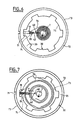
- Figures 3 and 4 show in section partial transverse anti-fall device according to a first embodiment of the invention.
- Figure 5 illustrates in detail the shape of the free end of the compensation spring shown in Figures 3 and 4.
- Figures 6 and 7 are diagrams of principle illustrating an anti-fall device according to a second embodiment of the invention.
- Figures 8 and 9 schematically represent a anti-fall device according to a third mode of realization of the invention.
- the vertical closing closure 1 illustrated in the figures 1 and 2 is curtain type with fixed shaft and winding manual.
- a system support 2 around which an apron 3 is wound sliding mounted between vertical slides 4, 5.
- Support system 2 consists of a series of compensating coils 6 with spring, movable mounted in rotation on a fixed shaft 7 via bearings 8, and connected transversely to each other by two reinforcing blades 9a, 9b secured at opposition on their respective circumferences.
- the apron 3 consists of a plurality of articulated blades 12; the one located at the upper end being secured to the blade of reinforcement 9b by screws 13.
- Each compensating coil 6 is provided with a spiral spring 14 not shown in FIG. 1 but visible in Figure 2.
- This compensation spring 14 takes place conventionally between the two flanges 15, 16 of coil 6 and its inner end 17 is secured to the shaft 7 by means of a fixing screw 18. Its outer end 19 is itself considered free, in the sense that it is not permanently attached but simply hooked to part of the coil 6.
- Figures 3 and 4 show a fall prevention device according to a first embodiment currently preferred of the invention, that is to say in which the locking element 20 is constituted by a finger 21 rotatably mounted on the reel 6.
- the organ static 30 is presented here in the form of a wheel toothed 31 having orthogonally two legs of fasteners 32a, 32b able to allow its connection on the shaft 7 via screws 33a, 33b.
- the wheel tooth 31 is positioned in the plane of rotation of the finger 21 pivotally mounted on the external face 22 of the flange 16.
- the axis of rotation 23 of the finger 21, also visible in Figure 1 is arranged such kind with respect to the contact surface of the wheel toothed 31, that said finger 21 is able to tilt from an open position not impeding the rotation of the coil 6, in an engaged position in which its end 24 comes into contact with said toothed wheel 31 until complete blocking once in abutment against a teeth 34.
- a means elastic return 40 In this example of embodiment, it is constituted by a spring 41 working in traction. Its presence is justified by the absolute necessity of having a reliable mechanism. A displacement under the sole action of gravity is only effect not sufficient to guarantee an engagement systematic, in particular due to the risks of untimely beating inherent in this type of mounting. Of course, it is quite possible to use a elastic return means 40 working in compression, by reverse positioning by relative to the locking element 20.
- the means of recall elastic 40 must therefore fill two functions. First, it must ensure the displacement of the locking element 20, then guarantee the support of the end 24 of the latter on the surface of contact of the static member 30, until blocking against a stop portion of said surface.
- the compensation spring 14 shown in the Figures 3 and 4 is actually located in the background relative to the flange 16 of the coil 6, that is to say housed in the space 50 between said flange 16 and the flange 15 ( Figure 1). Its free end 19 of curved shape partially wraps around of the axis of rotation 23, so that the latter is permanently subjected to the restoring force of said compensation spring 14.
- Axis 23 has longitudinally a flat 25, arranged orthogonally to the direction in which the finger 21 extends and cooperating by contact with a flat portion 51 formed at the free end 19 of the compensation spring 14. As the restoring force will be exerted essentially at this interface and significantly perpendicular, finger 21 is therefore advantageously maintained in a determined position corresponding to the previously opened position defined. This balance is not disturbed by the action of tension spring 41 due to the very intense greater than the force generated by the spring of compensation 14.
- This embodiment appears quite advantageous, since like a mechanism it is always possible to reassemble the deck 3 by rotating the carrying system 2, all by preventing the demotion of the movement of rotation.
- the free end 19 of the compensation spring 14 has a curved shape over 180 degrees. This peculiarity allows it not to offer protruding edges likely to catch the inside of the blades 12 of the deck 3 or that of the reinforcement strips 9a 9b, after the failure of said compensation spring 14, i.e. a rupture or significant load shedding.
- Its most distal part 52 that is to say that which extends substantially parallel to part 53 located just before the portion plane 51, advantageously forms a sort of suitable shoe to slide along the different elements previously mentioned.
- the anti-fall device includes stop means 60 able to control the swelling of the spring compensation 14, by limiting its radial expansion after a major break or load shedding.
- these abutment means 60 are constituted by an axis of retainer 61 arranged perpendicularly between the flanges 15, 16, near the axis of rotation 23 of the finger 21.
- the stop means 60 are preferably positioned at proximity of the locking element 20, so that that the compensation spring 14 cannot in particular disrupt the movement of this movable member.
- the second illustrated embodiment schematically in Figures 6 and 7 works on the same principle as that shown in Figures 3 and 4.
- This variant simply differs in the fact that the locking element 20 is here mounted movable in radial translation on the coil 73 and that it cooperates with a static member 30 consisting of a crown 35 with internal teeth.
- the blocking element 20 is on the one hand kept away from said crown 35 under the effect of the restoring force exerted by a spring of compensation 70, and on the other hand subject to the action of a elastic return means 40 here having the form of a spring 42 working in compression.
- the element of blocking 20 is constituted by a flat 74 mounted movable in sliding along two rectilinear lights 71. These are respectively provided through the two flanges 72 of a compensating coil 73, in a substantially radial direction. Any either its position in radial translation, the plate 74 crosses right through the coil 73, so that one of its ends extends beyond of the external wall of the flange 72 positioned directly near the static member 30.
- the part of the dish 74 located between the two flanges 72 advantageously serves as an attachment zone for the free end 19 of the compensation spring 70.
- the part projecting from the surface of the coil 73 comes to cut the following plan which is arranged the toothed crown 35.
- the assembly is arranged so that the dish 74 is able to stand move between a cleared position that does not hinder the rotation of the coil 73, and a position engaged in which its end comes into contact with the crown 35 until complete blocking once in abutment against one of the teeth 75.
- the dish 74 is able to cooperate by blocking with the static member 30 in the event of failure of the compensation spring 70.
- the dish 74 is driven in radial translation under the combined action of thrust generated by the compression spring 42 and from that resulting from the radial expansion of the spring of compensation 70 in the direction of arrow F.
- the outermost turn of the spring compensation 70 will first deploy radially until it comes into contact with the part of the dish 74 which is located between the two flanges 72 of the coil 73.
- the plate 74 is also mounted mobile in translation in the same direction as the expansion of the compensation spring 70 at this location precise, he will therefore be trained in displacement until it comes into abutment against the crown 35.
- the coil 73 is then seen to be immobilized in rotation relative to the static member 30 secured to the shaft fixed 7, thus stopping the fall of the apron 3 of the closing 1.
- the blocking element 20 is mounted movable in transverse translation on a compensating coil 80.
- a compensating coil 80 is constituted by a sliding pin 81 capable of being move in a direction substantially parallel to the axis of rotation of the coil 80.
- the axis 81 cooperates by sliding with two 82.83 bores of forms complementary to its section, arranged opposite on the two flanges 84.85.
- the sliding pin 81 is provided of an imprint 86 able to cooperate by fitting in less partial with a portion, substantially shaped complementary, of the free end 19 of the spring of compensation 87. Also, even if it is subject to permanence to a compression spring 88, the axis 81 is immobilized in translation under the effect of the force of reminder exercised by the compensation spring 87.
- imprint 86, of shape complementary to the free end 19, allows a real interlocking and therefore eliminating advantageously the risks of slipping.
- the helical wheel 89 also provides, like all the other static organs 30 previously described, immobilization in rotation of the coil 80 in accordance with the object of the present invention. This function is performed as soon as the sliding pin 81 comes in abutment against the edge 92 of one of the blades 90, after that its end 91 has possibly slipped against the surface of the blade directly adjacent to said edge 92.
- the coil 80 goes into first turn slightly in the opposite direction under the effect of the weight of the deck 3. In a second time, it will stop as soon as the axis sliding 81 will again lean against the edge 92 of one of the blades 90 of the helical wheel 89, stopping thus the descent of the deck 3.
- the static member 30 can in particular take any form likely to present at least a part forming stop; the distance between two stops successive precisely corresponding to the distance traversed by the deck 3 during its fall.
- the height of fall of the apron 3 is limited to the distance separating each tooth 34, 74.
Landscapes
- Engineering & Computer Science (AREA)
- Structural Engineering (AREA)
- Architecture (AREA)
- Civil Engineering (AREA)
- Operating, Guiding And Securing Of Roll- Type Closing Members (AREA)
- Ladders (AREA)
- Pivots And Pivotal Connections (AREA)
- Lock And Its Accessories (AREA)
- Forklifts And Lifting Vehicles (AREA)
- Support Of Aerials (AREA)
Description
Claims (15)
- Dispositif anti-chute pour fermeture à effacement vertical (1) par enroulement, ladite fermeture (1) comportant un tablier (3) apte à être enroulé autour d'au moins une bobine (6, 73, 80) montée mobile en rotation sur un arbre fixe (7), chaque bobine mobile (6, 73, 80) étant reliée à l'arbre fixe (7) par l'intermédiaire d'un ressort de compensation de type spiral (14, 70, 87), un dispositif anti-chute étant associé à chaque ressort de compensation (14, 70, 87), chaque dispositif anti-chute étant destiné à bloquer la descente du tablier (3) en cas de défaillance du ressort de compensation de type spiral (14, 70, 87) correspondant, chaque dispositif anti-chute comportant un élément de blocage (20) monté mobile sur la bobine (6, 73, 80) correspondante ainsi qu'un organe statique (30) solidaire de l'arbre fixe (7), l'élément de blocage (20) coopérant avec un moyen de rappel élastique (40) apte à le déplacer en direction de l'organe statique (30) dont la portion de surface destinée à entrer en contact avec ledit élément de blocage (20) présente au moins une partie formant butée, caractérisé en ce que l'élément de blocage (20) est maintenu à distance de l'organe statique (30) par la force de rappel exercée par le ressort de compensation de type spiral (14, 70, 87), au niveau de son extrémité libre (19), de forme recourbée, venant s'enrouler partiellement, directement ou indirectement, sur l'élément de blocage.
- Dispositif anti-chute selon la revendication 1, caractérisé en ce que l'extrémité libre (19) du ressort de compensation (14, 70, 87) coopère par contact direct avec l'élément de blocage (20) afin d'assurer elle-même l'immobilisation dudit élément de blocage (20) dans une position à l'écart de l'organe statique (30).
- Dispositif anti-chute selon l'une des revendications 1 ou 2, caractérisé en ce que l'élément de blocage (20) est monté mobile en rotation sur la bobine (6).
- Dispositif anti-chute selon la revendication 3, caractérisé en ce que l'élément de blocage (20) mobile en rotation est constitué par un doigt (21) dont l'axe de rotation (23) présente un méplat (25) apte à coopérer par contact avec une portion plane (51) de l'extrémité libre (19) du ressort de compensation (14).
- Dispositif anti-chute selon l'une des revendications 1 ou 2, caractérisé en ce que l'élément de blocage (20) est monté mobile en translation sur la bobine (73, 80).
- Dispositif anti-chute selon la revendication 5, caractérisé en ce que la mobilité en translation de l'élément de blocage (20) sur la bobine (73) s'exerce suivant une direction sensiblement radiale.
- Dispositif anti-chute selon la revendication 6, caractérisé en ce que l'élément de blocage (20) mobile en translation radiale est constitué par un plat (74) sur lequel vient s'accrocher l'extrémité libre (19) du ressort de compensation (70), ledit plat (74) coopérant par coulissement avec au moins une lumière (71) ménagée radialement sur un des flasques (72) de la bobine (73).
- Dispositif anti-chute selon l'une quelconque des revendications 1 à 7, caractérisé en ce que l'organe statique (30) est constitué par une roue dentée (31).
- Dispositif anti-chute selon l'une quelconque des revendications 1 à 7, caractérisé en ce que l'organe statique (30) est constitué par une couronne (35) dotée d'une denture intérieure.
- Dispositif anti-chute selon la revendication 5, caractérisé en ce que la mobilité en translation de l'élément de blocage (20) sur la bobine (80) s'exerce suivant une direction sensiblement parallèle à l'axe de rotation de ladite bobine (80).
- Dispositif anti-chute selon la revendication 10, caractérisé en ce que l'élément de blocage (20) mobile en translation transversale est constitué par un axe coulissant (81) comportant une empreinte (86) apte à coopérer par emboítement avec une portion, de forme sensiblement complémentaire, de l'extrémité libre (19) du ressort de compensation (87).
- Dispositif anti-chute selon la revendication 10 ou 11, caractérisé en ce que l'organe statique (30) est constitué par une roue en hélice (89) comportant des pales (90) aptes à immobiliser l'élément de blocage (20) en translation lorsque le ressort de compensation (87) est défaillant, quelle que soit la position relative de la bobine (80) par rapport audit organe statique (30).
- Dispositif anti-chute selon l'une quelconque des revendications 1 à 12, caractérisé en ce qu'il comporte des moyens de butée (60) aptes à limiter l'expansion radiale du ressort de compensation (14) en cas de rupture ou de délestage important.
- Dispositif anti-chute selon la revendication 13, caractérisé en ce que les moyens de butée (60) sont constitués par un axe de retenue (61) disposé perpendiculairement entre les flasques (15, 16) de la bobine (6), à proximité de l'élément de blocage (20).
- Dispositif anti-chute selon l'une quelconque des revendications 1 à 14, caractérisé en ce que l'extrémité libre (19) du ressort de compensation (14) présente une forme recourbée dont la partie (52) la plus distale, formant patin, est apte à glisser le long des différents éléments avec lesquels ladite extrémité libre (19) est susceptible de venir en contact en cas de défaillance dudit ressort de compensation (14).
Applications Claiming Priority (2)
| Application Number | Priority Date | Filing Date | Title |
|---|---|---|---|
| FR9614837 | 1996-11-28 | ||
| FR9614837A FR2756319B1 (fr) | 1996-11-28 | 1996-11-28 | Dispositif anti-chute pour fermetures a effacement vertical |
Publications (2)
| Publication Number | Publication Date |
|---|---|
| EP0845575A1 EP0845575A1 (fr) | 1998-06-03 |
| EP0845575B1 true EP0845575B1 (fr) | 2003-07-23 |
Family
ID=9498299
Family Applications (1)
| Application Number | Title | Priority Date | Filing Date |
|---|---|---|---|
| EP97402868A Expired - Lifetime EP0845575B1 (fr) | 1996-11-28 | 1997-11-26 | Dispositif anti-chute pour fermetures à effacement vertical |
Country Status (6)
| Country | Link |
|---|---|
| EP (1) | EP0845575B1 (fr) |
| AT (1) | ATE245760T1 (fr) |
| DE (1) | DE69723655T2 (fr) |
| ES (1) | ES2202565T3 (fr) |
| FR (1) | FR2756319B1 (fr) |
| PT (1) | PT845575E (fr) |
Families Citing this family (14)
| Publication number | Priority date | Publication date | Assignee | Title |
|---|---|---|---|---|
| FR2790033B1 (fr) | 1999-02-19 | 2001-06-08 | Profilmar | Dispositif antichute pour fermeture a deplacement vertical |
| FR2793837B1 (fr) | 1999-05-21 | 2001-07-13 | France Fermetures | Dispositif de securite anti-chute pour fermeture a effacement vertical |
| FR2793838B1 (fr) | 1999-05-21 | 2001-07-13 | France Fermetures | Dispositif de securite anti-chute pour fermetures a effacement vertical |
| FR2822190B1 (fr) * | 2001-03-16 | 2003-11-28 | Simu | Dispositif de securite pour installation de fermeture ou de protection solaire et mecanisme de manoeuvre d'une telle installation |
| FR2826688B1 (fr) | 2001-06-28 | 2004-01-23 | Bmj | Dispositif anti-chute pour fermeture a enroulement |
| ITPD20030052A1 (it) * | 2003-03-17 | 2004-09-18 | Ballan Spa | Dispositivo di sicurezza anticaduta per portoni sezionali |
| FR2871841B1 (fr) * | 2004-06-22 | 2006-08-11 | Bmj Sarl | Systeme de deblocage d'un dispositif anti-chute pour fermeture a enroulement |
| FR2871840B1 (fr) | 2004-06-22 | 2006-08-11 | Bmj Sarl | Systeme de deblocage d'un dispositif anti-chute pour fermeture a enroulement |
| FR2875838B1 (fr) | 2004-09-30 | 2006-12-08 | Profilmar Sa | Boite a ressort de dispositif antichute pour rideau roulant a deplacement vertical, et son procede de montage. |
| FR2884279B1 (fr) * | 2005-04-06 | 2007-05-25 | Michel Javey | Dispositif anti-chute pour fermeture a enroulement avec ou sans systeme de deblocage |
| GB2428758B (en) * | 2005-07-26 | 2008-01-16 | Alan Paul Young | Roller shutter braking mechanism |
| FR2919013B1 (fr) | 2007-07-20 | 2009-09-18 | Profilmar Sa | Boite a ressort de dispositif antichute de rideau roulant a deplacement vertical munie d'une surete,et elements de surete correspondants. |
| SE546418C2 (sv) * | 2021-06-17 | 2024-10-29 | Anders Beyron | Fallskyddsanordning, samt vertikalgående industriport med fallskyddsanordning |
| ES2992896B2 (es) * | 2023-06-19 | 2025-08-08 | Reductores Cunat S A | Sistema de paracaídas para cierres de accionamiento vertical |
Family Cites Families (5)
| Publication number | Priority date | Publication date | Assignee | Title |
|---|---|---|---|---|
| DE848613C (de) * | 1949-12-20 | 1952-09-04 | Oesterheld & Co | Von Hand bedienbares Rollenlager-Federgehaeuse fuer schwere Rollaeden, z. B. Garagen- oder Fabriktore u. dgl. |
| FR1204831A (fr) * | 1957-10-07 | 1960-01-28 | Dispositif pour la commande d'un volet | |
| DE3941084C2 (de) * | 1989-12-13 | 1997-05-15 | Mfz Antriebe Gmbh | Federbruchsicherung für Torwellen von Sektionaltoren |
| EP0722031A1 (fr) * | 1995-01-13 | 1996-07-17 | Hörmann Kg Dissen | Dispositif de surveillance d'un ressort de torsion précontraint |
| FR2739656B1 (fr) * | 1995-10-09 | 1997-11-21 | Tournier Gerard | Dispositif d'actionnement d'une fermeture a enroulement |
-
1996
- 1996-11-28 FR FR9614837A patent/FR2756319B1/fr not_active Expired - Lifetime
-
1997
- 1997-11-26 ES ES97402868T patent/ES2202565T3/es not_active Expired - Lifetime
- 1997-11-26 AT AT97402868T patent/ATE245760T1/de not_active IP Right Cessation
- 1997-11-26 PT PT97402868T patent/PT845575E/pt unknown
- 1997-11-26 EP EP97402868A patent/EP0845575B1/fr not_active Expired - Lifetime
- 1997-11-26 DE DE69723655T patent/DE69723655T2/de not_active Expired - Fee Related
Also Published As
| Publication number | Publication date |
|---|---|
| ATE245760T1 (de) | 2003-08-15 |
| DE69723655T2 (de) | 2004-06-09 |
| FR2756319B1 (fr) | 1999-05-21 |
| DE69723655D1 (de) | 2003-08-28 |
| PT845575E (pt) | 2003-12-31 |
| ES2202565T3 (es) | 2004-04-01 |
| EP0845575A1 (fr) | 1998-06-03 |
| FR2756319A1 (fr) | 1998-05-29 |
Similar Documents
| Publication | Publication Date | Title |
|---|---|---|
| EP3581742B1 (fr) | Poignée de porte affleurante et son procédé de fonctionnement | |
| EP1648737B1 (fr) | Dispositif de vision arriere pour vehicule automobile | |
| EP0845575A1 (fr) | Dispositif anti-chute pour fermetures à effacement vertical | |
| EP1270866B1 (fr) | Dispositif anti-chute pour fermeture à enroulement | |
| FR2766868A1 (fr) | Dispositif de securite anti-chute pour rideau de fermeture a effacement vertical dote d'un tablier compense par des ressorts montes autour d'un tube fixe | |
| EP1488070B1 (fr) | Dispositif de securite et mecanisme de manoeuvre d'une installation de fermeture ou de protection solaire incorporant un tel dispositif | |
| EP0768445B1 (fr) | Dispositif de fermeture à enroulement à axe fixe, ressort d'équilibrage et dispositif de verrouillage | |
| EP0922832B1 (fr) | Dispositif de retenue pour fermeture à enroulement | |
| EP1816294B1 (fr) | Boîte à ressort de dispositif antichute de rideau roulant à déplacement vertical | |
| WO2009034102A1 (fr) | Dispositif d'écartement provisoire muni de moyens de verrouillage | |
| FR2919013A1 (fr) | Boite a ressort de dispositif antichute de rideau roulant a deplacement vertical munie d'une surete,et elements de surete correspondants. | |
| FR2966189A1 (fr) | Dispositif de blocage d'une barre de charge d'un ecran et installation de fermeture ou de protection solaire equipee d'un tel dispositif de blocage | |
| FR2790033A1 (fr) | Dispositif antichute pour fermeture a deplacement vertical | |
| FR2884279A1 (fr) | Dispositif anti-chute pour fermeture a enroulement avec ou sans systeme de deblocage | |
| EP1609940B1 (fr) | Système de déblocage d'un dispositif anti-chute pour fermeture à enroulement | |
| EP0775605B1 (fr) | Store pare-soleil à mécanisme de déploiement par bielletes pivotantes | |
| FR2614928A1 (fr) | Volet roulant pour porte, fenetre et autres ouvertures | |
| EP2299039B1 (fr) | Dispositif de verrouillage-deverrouillage d'une porte de garage ou analogue | |
| FR2761402A1 (fr) | Dispositif d'autoblocage d'un tablier de volet roulant en position deployee | |
| FR2871840A1 (fr) | Systeme de deblocage d'un dispositif anti-chute pour fermeture a enroulement | |
| FR2793837A1 (fr) | Dispositif de securite anti-chute pour fermeture a effacement vertical | |
| FR2487422A1 (fr) | Perfectionnements aux dispositifs de verrouillage automatique de volets roulants | |
| EP1844210A1 (fr) | Dispositif de freinage de la rotation d'un arbre d'entrainement du tablier d'une porte rapide | |
| EP4039937A1 (fr) | Dispositif d'enroulement d'une toile de store | |
| FR2793838A1 (fr) | Dispositif de securite anti-chute pour fermetures a effacement vertical |
Legal Events
| Date | Code | Title | Description |
|---|---|---|---|
| PUAI | Public reference made under article 153(3) epc to a published international application that has entered the european phase |
Free format text: ORIGINAL CODE: 0009012 |
|
| AK | Designated contracting states |
Kind code of ref document: A1 Designated state(s): AT BE DE DK ES FR GB IT NL PT |
|
| AX | Request for extension of the european patent |
Free format text: AL;LT;LV;MK;RO;SI |
|
| 17P | Request for examination filed |
Effective date: 19980526 |
|
| AKX | Designation fees paid |
Free format text: AT BE DE DK ES FR GB IT NL PT |
|
| RBV | Designated contracting states (corrected) |
Designated state(s): AT BE DE DK ES FR GB IT NL PT |
|
| 17Q | First examination report despatched |
Effective date: 20020320 |
|
| GRAH | Despatch of communication of intention to grant a patent |
Free format text: ORIGINAL CODE: EPIDOS IGRA |
|
| GRAH | Despatch of communication of intention to grant a patent |
Free format text: ORIGINAL CODE: EPIDOS IGRA |
|
| RBV | Designated contracting states (corrected) |
Designated state(s): AT BE DE DK ES GB IT NL PT |
|
| GRAA | (expected) grant |
Free format text: ORIGINAL CODE: 0009210 |
|
| AK | Designated contracting states |
Designated state(s): AT BE DE DK ES GB IT NL PT |
|
| REG | Reference to a national code |
Ref country code: GB Ref legal event code: FG4D Free format text: NOT ENGLISH |
|
| GBT | Gb: translation of ep patent filed (gb section 77(6)(a)/1977) |
Effective date: 20030723 |
|
| REF | Corresponds to: |
Ref document number: 69723655 Country of ref document: DE Date of ref document: 20030828 Kind code of ref document: P |
|
| PG25 | Lapsed in a contracting state [announced via postgrant information from national office to epo] |
Ref country code: DK Free format text: LAPSE BECAUSE OF FAILURE TO SUBMIT A TRANSLATION OF THE DESCRIPTION OR TO PAY THE FEE WITHIN THE PRESCRIBED TIME-LIMIT Effective date: 20031023 |
|
| REG | Reference to a national code |
Ref country code: ES Ref legal event code: FG2A Ref document number: 2202565 Country of ref document: ES Kind code of ref document: T3 |
|
| PLBE | No opposition filed within time limit |
Free format text: ORIGINAL CODE: 0009261 |
|
| STAA | Information on the status of an ep patent application or granted ep patent |
Free format text: STATUS: NO OPPOSITION FILED WITHIN TIME LIMIT |
|
| 26N | No opposition filed |
Effective date: 20040426 |
|
| PGFP | Annual fee paid to national office [announced via postgrant information from national office to epo] |
Ref country code: DE Payment date: 20061108 Year of fee payment: 10 |
|
| PGFP | Annual fee paid to national office [announced via postgrant information from national office to epo] |
Ref country code: NL Payment date: 20061123 Year of fee payment: 10 Ref country code: BE Payment date: 20061123 Year of fee payment: 10 |
|
| PGFP | Annual fee paid to national office [announced via postgrant information from national office to epo] |
Ref country code: AT Payment date: 20061124 Year of fee payment: 10 |
|
| PGFP | Annual fee paid to national office [announced via postgrant information from national office to epo] |
Ref country code: GB Payment date: 20061127 Year of fee payment: 10 |
|
| BERE | Be: lapsed |
Owner name: JAVEY MICHEL Effective date: 20071130 |
|
| GBPC | Gb: european patent ceased through non-payment of renewal fee |
Effective date: 20071126 |
|
| NLV4 | Nl: lapsed or anulled due to non-payment of the annual fee |
Effective date: 20080601 |
|
| PG25 | Lapsed in a contracting state [announced via postgrant information from national office to epo] |
Ref country code: AT Free format text: LAPSE BECAUSE OF NON-PAYMENT OF DUE FEES Effective date: 20071126 |
|
| PG25 | Lapsed in a contracting state [announced via postgrant information from national office to epo] |
Ref country code: BE Free format text: LAPSE BECAUSE OF NON-PAYMENT OF DUE FEES Effective date: 20071130 |
|
| PG25 | Lapsed in a contracting state [announced via postgrant information from national office to epo] |
Ref country code: NL Free format text: LAPSE BECAUSE OF NON-PAYMENT OF DUE FEES Effective date: 20080601 Ref country code: DE Free format text: LAPSE BECAUSE OF NON-PAYMENT OF DUE FEES Effective date: 20080603 |
|
| PG25 | Lapsed in a contracting state [announced via postgrant information from national office to epo] |
Ref country code: GB Free format text: LAPSE BECAUSE OF NON-PAYMENT OF DUE FEES Effective date: 20071126 |
|
| PGFP | Annual fee paid to national office [announced via postgrant information from national office to epo] |
Ref country code: ES Payment date: 20091127 Year of fee payment: 13 |
|
| PGFP | Annual fee paid to national office [announced via postgrant information from national office to epo] |
Ref country code: PT Payment date: 20091124 Year of fee payment: 13 |
|
| REG | Reference to a national code |
Ref country code: PT Ref legal event code: MM4A Free format text: LAPSE DUE TO NON-PAYMENT OF FEES Effective date: 20110526 |
|
| PG25 | Lapsed in a contracting state [announced via postgrant information from national office to epo] |
Ref country code: PT Free format text: LAPSE BECAUSE OF NON-PAYMENT OF DUE FEES Effective date: 20110526 |
|
| REG | Reference to a national code |
Ref country code: ES Ref legal event code: FD2A Effective date: 20120110 |
|
| PG25 | Lapsed in a contracting state [announced via postgrant information from national office to epo] |
Ref country code: ES Free format text: LAPSE BECAUSE OF NON-PAYMENT OF DUE FEES Effective date: 20101127 |
|
| PGFP | Annual fee paid to national office [announced via postgrant information from national office to epo] |
Ref country code: IT Payment date: 20121026 Year of fee payment: 16 |
|
| PG25 | Lapsed in a contracting state [announced via postgrant information from national office to epo] |
Ref country code: IT Free format text: LAPSE BECAUSE OF NON-PAYMENT OF DUE FEES Effective date: 20131126 |