EP0845615B1 - Kupplungsausrüstvorrichtung - Google Patents
Kupplungsausrüstvorrichtung Download PDFInfo
- Publication number
- EP0845615B1 EP0845615B1 EP97402853A EP97402853A EP0845615B1 EP 0845615 B1 EP0845615 B1 EP 0845615B1 EP 97402853 A EP97402853 A EP 97402853A EP 97402853 A EP97402853 A EP 97402853A EP 0845615 B1 EP0845615 B1 EP 0845615B1
- Authority
- EP
- European Patent Office
- Prior art keywords
- diaphragm
- deformation
- fingers
- finger
- operating element
- Prior art date
- Legal status (The legal status is an assumption and is not a legal conclusion. Google has not performed a legal analysis and makes no representation as to the accuracy of the status listed.)
- Expired - Lifetime
Links
- 238000005096 rolling process Methods 0.000 claims description 19
- 239000000463 material Substances 0.000 claims description 15
- 239000002184 metal Substances 0.000 claims description 8
- 230000015572 biosynthetic process Effects 0.000 claims description 6
- 238000007373 indentation Methods 0.000 claims 2
- 238000004519 manufacturing process Methods 0.000 description 3
- 230000002093 peripheral effect Effects 0.000 description 3
- 238000005520 cutting process Methods 0.000 description 2
- 230000007547 defect Effects 0.000 description 2
- 238000006073 displacement reaction Methods 0.000 description 2
- 238000010438 heat treatment Methods 0.000 description 2
- 230000036316 preload Effects 0.000 description 2
- 241000269319 Squalius cephalus Species 0.000 description 1
- 230000005540 biological transmission Effects 0.000 description 1
- 230000008878 coupling Effects 0.000 description 1
- 238000010168 coupling process Methods 0.000 description 1
- 238000005859 coupling reaction Methods 0.000 description 1
- 238000002788 crimping Methods 0.000 description 1
- 230000007423 decrease Effects 0.000 description 1
- 239000013013 elastic material Substances 0.000 description 1
- 230000002045 lasting effect Effects 0.000 description 1
- 238000012423 maintenance Methods 0.000 description 1
- 238000000034 method Methods 0.000 description 1
- 210000000056 organ Anatomy 0.000 description 1
- 229940012982 picot Drugs 0.000 description 1
- 230000002035 prolonged effect Effects 0.000 description 1
- 238000010791 quenching Methods 0.000 description 1
- 230000000171 quenching effect Effects 0.000 description 1
- 230000003014 reinforcing effect Effects 0.000 description 1
- 238000007493 shaping process Methods 0.000 description 1
- 238000005728 strengthening Methods 0.000 description 1
- 229920002994 synthetic fiber Polymers 0.000 description 1
Images




Classifications
-
- F—MECHANICAL ENGINEERING; LIGHTING; HEATING; WEAPONS; BLASTING
- F16—ENGINEERING ELEMENTS AND UNITS; GENERAL MEASURES FOR PRODUCING AND MAINTAINING EFFECTIVE FUNCTIONING OF MACHINES OR INSTALLATIONS; THERMAL INSULATION IN GENERAL
- F16D—COUPLINGS FOR TRANSMITTING ROTATION; CLUTCHES; BRAKES
- F16D23/00—Details of mechanically-actuated clutches not specific for one distinct type
- F16D23/12—Mechanical clutch-actuating mechanisms arranged outside the clutch as such
- F16D23/14—Clutch-actuating sleeves or bearings; Actuating members directly connected to clutch-actuating sleeves or bearings
- F16D23/143—Arrangements or details for the connection between the release bearing and the diaphragm
Definitions
- the present invention relates to the field of devices declutchers for friction clutches of the thrust type, in particular for motor vehicles.
- Such devices include a clutch release bearing in support on the internal end of a centrally perforated diaphragm.
- the clutch release bearing has a rolling bearing of stop usually with concentric and coaxial rings, with a ring rotating, profiled for local contact with the diaphragm provided an outer peripheral part in the shape of a Belleville washer extended radially inwards by a central part fragmented into radial fingers separated in pairs by slits blind, the bottom or outer end of which is constituted by enlarged holes located on the inner periphery of the washer Belleville of the tapered diaphragm in the free state.
- the slots open internally into the central hole of the diaphragm.
- the rotating ring acts on the inner end of the fingers of the diaphragm and has a domed part, when the fingers of the diaphragm are planar and a planar annular shape when the fingers diaphragm are domed at their inner end.
- the non-rotating ring is, for operating the bearing at bearing, axially coupled to an operating element having a central sleeve mounted on a guide tube for movement axial of the operating element with respect to the guide tube through which a driven shaft, while the diaphragm is integral in rotation with a leading tree.
- the operating element thus carries the stop of walkout.
- the non-rotating ring of the rolling bearing can be fixed radially with respect to the operating element being, by example press fit on the front end of the sleeve the operating element.
- the rolling bearing can be move radially with respect to the operating element, the stop being then called self-centering declutching stop.
- Ways coupling of the non-rotating ring to the operating element then comprise, for example, elastic means with axial action such as an elastic washer of the Belleville washer type or of the type wavy washer. Alternatively it may be hooks or a radially deformable washer like a circlip.
- the elastic means bear directly on the operating element or on a cover secured by crimping or latching of said operating element to act on the ring not rotating and apply it in contact with an integral shoulder of the operating element.
- the operating element is shaped to be subjected to the action of mechanical type displacement control means, hydraulic or electromechanical. These control means allow the clutch release bearing to be moved axially with respect to to the guide tube.
- the guide tube is fixed directly on a part fixed such as the gearbox housing and the sleeve the operating element carries at its rear end a transverse flange, possibly coated with a support plate, on which act the fingers of a clutch release fork actuated by the clutch pedal with the intervention of a spring, called preload, in the kinematic chain going from the pedal to the fork.
- This preload spring keeps the stopper declutching with constant pressure on the diaphragm to reduce wear and increase the service life of the bearing.
- the operating element By manipulating the fork, the operating element is moved axially along the guide tube so that the clutch release bearing acts by pushing on the end internal of the diaphragm fingers, the latter bringing the stopper to its initial position as soon as you stop acting on the clutch pedal.
- the sleeve of the operating element may consist of a piston of a hydraulic control comprising a fixed part, by example fixed on the gearbox housing and defining a blind cavity inside which the seal moves piston.
- the guide tube is threaded and cooperates with the sleeve of the operating element forming a nut while being mounted on the guide tube forming a screw.
- This tube is movable in rotation and is fixed axially, while the sleeve is fixed in rotation, for example at using elastic tabs connecting the sleeve to a fixed housing, and is mobile in translation.
- the guide tube is then carried by the housing fixed by means of a bearing. Using a cable, we move in rotation the guide tube and in translation the sleeve.
- the guide tube can also be rotated by an electric motor secured to a fixed part.
- the diaphragm undergoes operations mechanical cutting and conical shaping as well as heat treatment operations, in particular quenching, in order to give the desired shape as well as the desired hardness and elasticity. This results in certain geometric defects, and in practice the the tips of the diaphragm fingers are not all in the same plan.
- Document FR-A-2 234 485 (RANSOME HOFFMANN POLLARD) relates to a conventional clutch in which the diaphragm is mounted under stress and is supported on a primary support carried by the centrally perforated bottom of a fixed hollow cover, by example by screws, to a steering wheel integral in rotation of a leading tree.
- the primary support is annular in shape and is produced by stamping the bottom of the cover or alternatively consists in a ring carried by columns fixed by riveting to the bottom of the cover and each passing through an enlarged orifice of the diaphragm for wear a ring, forming a secondary support, placed opposite the support primary by being interposed between the heads of the balusters and the diaphragm on the side thereof, turned away from the bottom of the lid.
- the balusters are replaced by legs issues by cutting and folding the bottom of the cover.
- the paws pass through enlarged apertures in the diaphragm and are folded back at their free end radially outward to form a bend of setting for a crown ring with a rounded part for contact with the face of the diaphragm turned away from the bottom of the cover and thus form the secondary support.
- the inner periphery of the Belleville washer is pivotally mounted between the primary and secondary supports located opposite.
- the suburbs of the Belleville washer is based on a fragmented boss that presents the dorsal face of a pressure plate linked in rotation to the cover while being axially movable relative to the cover, usually with elastic orientation tabs tangential.
- Friction linings of a friction disc are axially interposed between the drive wheel and the face front of the pressure plate. At its internal periphery the disc of friction presents a hub for its rotation setting on a shaft conducted.
- the driven shaft is the input shaft of the gearbox, and the shaft leading is the crankshaft of the vehicle engine on which the driving wheel.
- the diaphragm When the clutch is engaged, the diaphragm is supported on the primary support and on the boss of the pressure plate to push it towards the steering wheel and tighten the trim friction. The torque is thus transmitted from the shaft leading to the driven shaft.
- we deactivate the means. by moving the element from maneuver so that the rotating ring pushes on the diaphragm. The latter then takes support on its secondary support and switches from so that the load it exerts on the pressure plate decreases gradually then vanishes.
- the elastic tabs recall the pressure plate towards the bottom of the cover to release the friction linings.
- the balusters or the legs are therefore requested at each clutch release operation.
- Document FR-A-2 234 485 proposes to carry out a positive drive between the rotating ring of the clutch release bearing, carried by the clutch cover, and the diaphragm.
- the ring rotating is mounted on or in a sleeve fixed on the cover to using the balusters and has two diametrically protruding opposite, which each enter a slit in the diaphragm.
- It certain drawbacks result because the release bearing is no longer standard type, the clutch cover is stressed additional and dynamic balancing issues of the clutch appear because the cover carries the stopper walkout.
- the rotating ring of the bearing must be relatively massive because it is mounted integral with a support sleeve and undergoes additional stresses, especially when it slides axially with respect to the sleeve.
- the object of the present invention is to remedy these different disadvantages and to propose a declutching device simple and economical.
- the object of the present invention is, in particular to propose a declutching device in which the rotating ring, weak thickness, is in direct and permanent contact in all circumstances with the diaphragm, the latter being provided with slots the width of which is independent of the stop.
- the declutching device comprises a diaphragm provided with a central hole and cut into oriented fingers radially inwards, a thrust bearing and a operating element mounted on a separate part from that supporting the diaphragm and in at least axial contact with the bearing to rolling.
- the rolling bearing includes a rotating ring, a radial portion is supported on the inner end of the fingers of the diaphragm, a non-rotating ring of which a radial portion is in contact with the operating element, and a row of elements rolling.
- the rotating ring is made of pressed sheet metal and includes on its radial portion in contact with the diaphragm, at least one axial deformation obtained without removal of material, and the edges are able to cooperate with the sides of a finger of the diaphragm, the deformation being of dimension smaller than the thickness of a diaphragm finger.
- the axial deformation can be obtained for example at by means of a press.
- a clutch device is obtained which clean the clutch cover, and you can use a stopper standard type clutch because the operating element is not not carried by the same part as the diaphragm.
- Only the ring of the rolling bearing is changed so that economical because, on the one hand, the rotating ring is thin and, on the other hand, the deformations are of small axial dimensions.
- the deformations are carried out without removal of chips, which can be carried out easily and economically during the process stamping the ring.
- the invention takes advantage of geometric defects of the diaphragm fingers which allow to use deformations of small dimensions. The deformation will engage the flank of one of the most diaphragm fingers axially offset from the others.
- the number of deformations required is very weak due to the fact that once the positive rotating link is established between the diaphragm and the rotating ring of the stop, this connection will have tendency to strengthen with the duration of operation of the stop.
- This incrustation phenomenon is made possible by the fact that the diaphragm fingers have a significant hardness, well than lower than that of the rotating ring which has a small thickness.
- a rotating ring in pressed sheet metal has a certain aptitude for local micro-deformations under the action of diaphragm fingers during disengagement operations which also promotes the phenomenon of incrustation.
- the deformation can consist of a pushing back material inward, toward the rolling elements of the rolling bearing.
- This material repel leads to the formation a depression in the form of a radial groove with lateral edges parallel to the lateral flanks of a diaphragm finger, the width of the groove being slightly greater than that of a finger of the diaphragm.
- the stop is brought into contact with the diaphragm in any circumferential position, and any rotation relative of the diaphragm with respect to the stop leads to one of the fingers, which is one of the most axially offset to others, engages in depression causing a bond positive in rotation between the diaphragm and the clutch release bearing.
- the material can be pushed back towards outside, in the direction opposite to the rolling elements of said bearing and lead to the formation of a proper axial protuberance to come in taken with an edge of one of the most axially offset fingers to positive connection in rotation between the diaphragm and the stop.
- This protrusion may, for example, form a spike radially oblong shape and less width than a slit forming a circumferential space between two adjacent fingers of the diaphragm.
- the protuberance can also be obtained by a puncture of the sheet metal leading to the formation of an inclined leg whose edge radial is projecting.
- the diaphragm may have slots of constant width below the widened orifices, or slits of width reduced to its inner end to increase the contact area of the diaphragm and the rotating ring.
- the invention is therefore of universal use since the deformation is carried out without removal of material and from a stamped ring of small thickness. Indeed, even in the case where the material deformation takes place outwards, it is easy to control it to be less than the width of a slit of reduced width. It is for this reason that the deformation is present, in this case, in the form of a picot or a puncture.
- the material repulsion is performed before the ring heat treatment operations rotating intended to give it the desired hardness.
- the deformation is of axial height less than half the thickness of a diaphragm finger.
- two diametrically deformations opposite are planned.
- the device according to the invention could advantageously be used in combination with a wear take-up system the clutch which will guarantee the maintenance of a dimensional range stable slots circumferentially separating the fingers from the diaphragm regardless of clutch wear.
- the operating element may have a central sleeve for axial sliding along a guide tube integral with a part fixed, for example the gearbox housing separate from the block motor carrying the diaphragm.
- the sleeve may form a nut driven in translation by the guide tube forming the screw itself rotatably mounted.
- the operating element can be mechanically actuated for example by a cable or a fork, hydraulically in in this case forming a piston or electromechanically.
- the element of maneuver is shaped to be mounted on a separate part of the one with the diaphragm.
- the rotating ring can be the inner or outer ring of the thrust bearing.
- the diaphragm 1 includes an external peripheral part 2 in the form of a washer Belleville frustoconical in the free state, and a central part 3 located in the radial extension towards the inside of the external part 2, and which is circularly fragmented (cut) into radial fingers 4 by grooves forming slots 5.
- Each slot 5 extends from a enlarged blind outer end 6 located on the inner periphery of the peripheral part 2, at an open internal end 7, which is reduced circumferential width, and opens into a central hole 8 common to all slots 5.
- the reduced width of the slots 5 at their end open 7 is obtained, for example by slicing operations.
- the two radial edges can be produced in two separate operations 9 and 10 of such a slot 5, namely, a first slicing operation during which one of the edges 9, 10 is first produced by question and then a second slicing operation during which the other of said edges is subsequently called flanks 4a.
- the fingers 4 of the diaphragm 1 as shown in Figure 2 are all located on the same frustoconical surface of revolution.
- a diaphragm 1 real will have fingers 4 more or less offset axially in one direction or another taking into account the manufacturing method supra of the diaphragm.
- the declutching device includes a diaphragm 1, a clutch stop 11 and a guide tube 12 partially shown.
- the stop 11 is slidably mounted axially on a guide tube 12 mounted on the gearbox casing speeds, not shown, and therefore on a separate part from that bearing the diaphragm.
- the stop 11 includes a rolling bearing of stop 13, an operating element 14 subjected to the action of a control 15, here a clutch release fork.
- Thrust bearing 13 includes a rotating inner ring 16, made of thin sheet metal, and a non-rotating outer ring 17 also made of sheet metal thin, between which is a row of rolling elements, for example balls 18 held by a cage 19.
- a seal seal 20 is fitted onto a bore of the outer ring 17 on the side of the diaphragm 1.
- the outer ring 17 comprises on the side opposite to the diaphragm 1, a radial portion 21.
- the operating element 14 comprises a cylindrical portion 22 and a radial flange 23 directed inwards against which come to bear, on one side the radial portion 21 of the outer ring 17, and on the other side the control member 15 via the clutch release fingers.
- the outer ring 17 of the thrust bearing 13 is kept in contact with said flange radial 23 by a biconical washer 24 whose outer edge bears on the radial portion 21 of the outer ring 17 and whose inner edge, cut into tabs, is housed in a groove 22a of the portion cylindrical 22 of the operating element 14, thereby ensuring the axial support of the thrust bearing 13 against the operating element 14.
- the bearing stop can move radially in a controlled manner relative to the operating element 14 and thus come to center in operation with respect to the diaphragm.
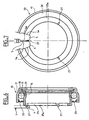
- the inner rotating ring 16 of the thrust bearing 13 comprises, at its end directed towards the diaphragm 1, a portion radial 25 provided on its outer edge with a rounded surface convex 25a in contact with the end of the fingers 4 of the diaphragm 1.
- the depth of the depression 26 is significantly less than half the thickness of a finger 4 of the diaphragm 1.
- a finger 4 of the latter is housed in the depression 26 and prevents any subsequent relative rotation of the stop 11 and diaphragm 1.
- the sides 4a of fingers 4 can come into contact with edges 26a of depressions 26.
- the edges 26a may come into contact with a side 4a with a finger 4.
- the diaphragm 1 and the rotating ring 16 are integral in rotation.
- the rotating inner ring 16 includes three protrusions 27 projecting and in the form of pins between two adjacent fingers 4 of the diaphragm 1.
- the protrusions 27 are radially shaped oblong and of very small circumferential dimensions so as to come and lodge in any of the slots 5 separating the fingers 4 of the diaphragm 1.
- the protrusions 27 are of thickness less than that of the fingers 4 of the diaphragm 1 being radially shaped oblong for good contact with said fingers.
- FIGS. 8 and 9 The embodiment illustrated in FIGS. 8 and 9 is similar to that of Figures 6 and 7 except that the protrusions 127 are obtained by puncturing the sheet metal leading to the formation of inclined legs 27, the radial edge of which protrudes and is adapted to engage with one of the sides 4a of a finger 4 while being parallel to said flank 4a.
- the material is pushed outward without removal of chips and the protrusions 27, 127 are parallel to the sides 4a.
- the declutching device comprises a diaphragm 1 identical to that of FIGS. 1 and 2 and a stop 11 slightly different from that of FIGS. 3 to 5, in that it comprises a thrust bearing 13 provided with an outer rotating ring 16, and an inner non-rotating ring 17, between which is disposed a row of balls 18.
- the rotating ring 16 supports, on the side of the operating element 14, a seal 20.
- the rotating ring 16 comprises a radial portion 25 rounded and in contact with the fingers 4 of the diaphragm 1.
- Several depressions 26 are provided by pushing back the material forming the radial portion 25.
- a finger 4 can be housed in each depression 26.
- a member self-aligning elastic 30 allowing the radial displacement of the bearing 13 with respect to the operating element 14 and its self-centering with respect to the diaphragm.
- the elastic organ self-aligning 30 projects axially beyond the end of the non-rotating ring 17, in the direction of the rotating ring 16 to form a labyrinth seal 31.
- the present invention is not not limited to the embodiments described.
- the protrusions 27, 127 can be of different axial height so that the diaphragm fingers axially salient do not necessarily cooperate with protuberances.
- a clutch device is obtained economical with rolling bearing and diaphragm lasting prolonged life due to the rotational connection of the diaphragm with the rotating ring and which places less stress on the clutch housing, while suitable for any type of diaphragm including internally, the declutching device according to the invention can operate with a diaphragm with reduced width slots.
- the diaphragm is always in the same position when the clutch is engaged and that in no case can the width of the slits be reduced so that the ends of the diaphragm fingers can pinch the deformations when these consist of a material repulsion outwards.
Landscapes
- Engineering & Computer Science (AREA)
- General Engineering & Computer Science (AREA)
- Mechanical Engineering (AREA)
- Mechanical Operated Clutches (AREA)
Claims (13)
- Ausrückvorrichtung, zu der gehören: eine mit einer Zentralöffnung versehene Membranfeder (1), die einen mittleren Abschnitt aufweist, der durch Schlitze (5) in Finger (4) aufgeschnitten ist, die in radialer Richtung nach innen ausgerichtet sind, ein Ausrück-Wälzlager (13) und ein Betätigungselement (14), das auf einem von dem Teil, auf dem die Membranfeder befestigt ist, verschiedenen Teil angebracht ist und das zumindest in axialer Richtung mit dem Wälzlager in Berührung steht, wobei das Wälzlager einen umlaufenden Ring (16), der mit einem radialen Abschnitt an dem inneren Ende der Finger der Membranfeder anliegt, einen stillstehenden Ring (17), der mit einem radialen Abschnitt mit dem Betätigungselement in Berührung steht, und eine Reihe von Wälzkörpern (18) aufweist, dadurch gekennzeichnet, dass der aus umgeformtem Blech hergestellte umlaufende Ring auf dessen radialen Abschnitt, der mit der Membranfeder in Berührung steht, wenigstens eine axiale Verformung aufweist, die ohne Entfernen von Werkstoff erzeugt ist und deren Ränder in der Lage sind, mit den Flanken eines Fingers der Membranfeder zusammenzuwirken, wobei die Abmessung der Verformung geringer ist als die Dicke eines Fingers der Membranfeder.
- Vorrichtung nach Anspruch 1, dadurch gekennzeichnet, dass die Verformung durch Zurückdrängen von Material in Richtung der Wälzkörper (18) des Lagers nach innen erzeugt wird, was zu einer Ausbildung einer Vertiefung (26) führt.
- Vorrichtung nach Anspruch 2, dadurch gekennzeichnet, dass die Vertiefung (26) eine radiale Nut bildet, deren Breite in Umfangsrichtung größer ist als die Breite eines Fingers der Membranfeder.
- Vorrichtung nach Anspruch 1, dadurch gekennzeichnet, dass die Verformung durch Drängen von Material nach außen, in eine zu den Wälzkörpern (18) des Lagers entgegengesetzte Richtung erzeugt wird, wodurch die Ausbildung eines Vorsprungs (27, 127) entsteht.
- Vorrichtung nach Anspruch 4, dadurch gekennzeichnet, dass die Verformung einen Vorsprung (27, 127) bildet, dessen Abmessungen geringer sind als die Abmessungen des Raumes in Umfangsrichtung, der zwei benachbarte Finger der Membranfeder voneinander trennt.
- Vorrichtung nach Anspruch 5, dadurch gekennzeichnet, dass die Verformung einen Zahn (27) bildet, der in radialer Richtung eine längliche Gestalt aufweist.
- Vorrichtung nach Anspruch 5, dadurch gekennzeichnet, dass die Verformung (127) eine schräge Klaue mit einer radialen Kante bildet, die parallel zu der Flanke (4a) eines Fingers (4) der Membranfeder (1) verläuft.
- Vorrichtung nach einem der Ansprüche 5 bis 7, dadurch gekennzeichnet, dass die Vprsprünge (27, 127) unterschiedliche axiale Höhen aufweisen.
- Vorrichtung nach einem der vorhergehenden Ansprüche, dadurch gekennzeichnet, dass die Ränder (26a) der Verformung parallel zu den Flanken (4a) des entsprechenden Fingers (4) verlaufen.
- Vorrichtung nach einem der vorhergehenden Ansprüche, dadurch gekennzeichnet, dass die axiale Höhe der Verformung geringer ist als die halbe Dicke eines Fingers der Membranfeder.
- Vorrichtung nach einem der vorhergehenden Ansprüche, dadurch gekennzeichnet, dass der umlaufende Ring zwei einander diametral gegenüberliegende Verformungen aufweist.
- Vorrichtung nach einem der Ansprüche 1 bis 11, dadurch gekennzeichnet, dass der umlaufende Ring drei Verformungen aufweist, die in Umfangsrichtung gleichmäßig voneinander beabstandet sind.
- Vorrichtung nach einem der vorhergehenden Ansprüche, dadurch gekennzeichnet, dass das Betätigungselement verschiebbar an einem Führungsrohr befestigt ist.
Applications Claiming Priority (2)
| Application Number | Priority Date | Filing Date | Title |
|---|---|---|---|
| FR9614704 | 1996-11-29 | ||
| FR9614704A FR2756602B1 (fr) | 1996-11-29 | 1996-11-29 | Dispositif debrayeur |
Publications (2)
| Publication Number | Publication Date |
|---|---|
| EP0845615A1 EP0845615A1 (de) | 1998-06-03 |
| EP0845615B1 true EP0845615B1 (de) | 2003-04-23 |
Family
ID=9498201
Family Applications (1)
| Application Number | Title | Priority Date | Filing Date |
|---|---|---|---|
| EP97402853A Expired - Lifetime EP0845615B1 (de) | 1996-11-29 | 1997-11-27 | Kupplungsausrüstvorrichtung |
Country Status (6)
| Country | Link |
|---|---|
| US (1) | US5992598A (de) |
| EP (1) | EP0845615B1 (de) |
| KR (1) | KR100490513B1 (de) |
| BR (1) | BR9706052A (de) |
| DE (1) | DE69721193T2 (de) |
| FR (1) | FR2756602B1 (de) |
Families Citing this family (12)
| Publication number | Priority date | Publication date | Assignee | Title |
|---|---|---|---|---|
| DE102004003285A1 (de) † | 2003-02-01 | 2004-08-12 | Zf Sachs Ag | Reibungskupplung |
| DE102005023523A1 (de) * | 2005-05-21 | 2006-11-23 | Schaeffler Kg | Ausrücklager einer Schalttrennkupplung |
| DE102005032676B4 (de) * | 2005-07-13 | 2013-01-03 | Schaeffler Technologies AG & Co. KG | Kupplungsausrücklager im Kontakt mit einer Tellerfeder |
| DE102006024084A1 (de) * | 2006-05-23 | 2007-11-29 | Schaeffler Kg | Kupplungsausrücklager |
| FR2919033B1 (fr) * | 2007-07-20 | 2009-10-16 | Snr Roulements Sa | Procede de fabrication et rondelle d'autocentrage renforcee mecaniquement |
| EP2287486B1 (de) * | 2008-05-27 | 2019-07-10 | JTEKT Corporation | Kupplungsdrucklager |
| DE102012204590A1 (de) * | 2012-03-22 | 2013-09-26 | Schaeffler Technologies AG & Co. KG | Kupplungs-Ausrücklager |
| KR101416269B1 (ko) * | 2013-02-27 | 2014-07-07 | 셰플러코리아(유) | 클러치 릴리즈 베어링 |
| FR3031553B1 (fr) * | 2015-01-13 | 2017-08-18 | Skf Ab | Palier a roulement pour dispositif de butee de debrayage comprenant un revetement antifriction |
| DE102016210353A1 (de) | 2016-06-10 | 2017-12-14 | Schaeffler Technologies AG & Co. KG | Ausrücklager einer Reibungskupplung |
| KR102611404B1 (ko) * | 2016-10-05 | 2023-12-07 | 에이치엘만도 주식회사 | 전자식 주차 브레이크 |
| DE102017104201A1 (de) * | 2017-03-01 | 2018-09-06 | Knorr-Bremse Systeme für Nutzfahrzeuge GmbH | Kupplungslagerung mit Ausrichtungselement für Kupplungsfeder |
Family Cites Families (16)
| Publication number | Priority date | Publication date | Assignee | Title |
|---|---|---|---|---|
| DE2021627A1 (de) * | 1970-05-02 | 1972-01-05 | Schaeffler Ohg Industriewerk | Kupplungsausruecklager |
| DE2327023C3 (de) * | 1973-05-26 | 1978-10-12 | Skf Kugellagerfabriken Gmbh, 8720 Schweinfurt | Reibungskupplung mit integriertem Ausrücklager |
| DE2327022C3 (de) * | 1973-05-26 | 1978-10-12 | Skf Kugellagerfabriken Gmbh, 8720 Schweinfurt | Reibungskupplung, insbesondere für Kraftfahrzeuge |
| GB1478612A (en) * | 1973-06-20 | 1977-07-06 | Ransome Hoffmann Pollard | Clutch release mechanism |
| GB1508987A (en) * | 1974-06-07 | 1978-04-26 | Ransome Hoffmann Pollard | Thrust bearing for a clutch release mechanism |
| FR2452634A1 (fr) * | 1979-03-30 | 1980-10-24 | Skf Cie Applic Mecanique | Butee d'embrayage a auto-alignement elastique guide |
| DE8311155U1 (de) * | 1983-04-15 | 1983-07-07 | Skf Kugellagerfabriken Gmbh, 8720 Schweinfurt | Hydraulisch betaetigter kupplungsausruecker |
| FR2544429B1 (fr) * | 1983-04-15 | 1985-08-02 | Valeo | Procede pour le montage d'une butee de debrayage, et butee de debrayage correspondante, notamment pour vehicule automobile |
| DD226940A5 (de) * | 1983-08-05 | 1985-09-04 | Luk Lamellen & Kupplungsbau | Reibungskupplung |
| SE453216B (sv) * | 1986-05-14 | 1988-01-18 | Skf Nova Ab | Kopplingsanordning |
| JPS63246516A (ja) * | 1987-04-02 | 1988-10-13 | Nippon Seiko Kk | クラツチレリ−ズ軸受装置 |
| JPS6440723A (en) * | 1987-08-07 | 1989-02-13 | Nippon Seiko Kk | Clutch release bearing device |
| JPH01156321U (de) * | 1988-04-19 | 1989-10-27 | ||
| JPH022531U (de) * | 1988-06-17 | 1990-01-09 | ||
| FR2667121B1 (fr) * | 1990-09-25 | 1995-04-07 | Valeo | Dispositif de commande pour embrayage, notamment pour vehicules automobiles. |
| DE4120643B4 (de) * | 1991-06-22 | 2004-04-08 | Zf Sachs Ag | Reibungskupplung mit Wegsensor |
-
1996
- 1996-11-29 FR FR9614704A patent/FR2756602B1/fr not_active Expired - Fee Related
-
1997
- 1997-11-20 US US08/975,297 patent/US5992598A/en not_active Expired - Fee Related
- 1997-11-27 DE DE69721193T patent/DE69721193T2/de not_active Expired - Lifetime
- 1997-11-27 EP EP97402853A patent/EP0845615B1/de not_active Expired - Lifetime
- 1997-11-28 KR KR1019970063636A patent/KR100490513B1/ko not_active Expired - Fee Related
- 1997-11-28 BR BR9706052-6A patent/BR9706052A/pt not_active IP Right Cessation
Also Published As
| Publication number | Publication date |
|---|---|
| FR2756602B1 (fr) | 1999-01-15 |
| KR100490513B1 (ko) | 2005-09-30 |
| US5992598A (en) | 1999-11-30 |
| BR9706052A (pt) | 1999-09-14 |
| KR19980042863A (ko) | 1998-08-17 |
| EP0845615A1 (de) | 1998-06-03 |
| FR2756602A1 (fr) | 1998-06-05 |
| DE69721193T2 (de) | 2004-02-05 |
| DE69721193D1 (de) | 2003-05-28 |
Similar Documents
| Publication | Publication Date | Title |
|---|---|---|
| EP0845615B1 (de) | Kupplungsausrüstvorrichtung | |
| EP0228310B1 (de) | Tellerfederkupplungsmechanismus, insbesondere für Kraftfahrzeuge und entsprechende Kupplung | |
| FR2619880A1 (fr) | Butee de debrayage, notamment pour vehicules automobiles | |
| EP3494323B1 (de) | Kompakter doppelkupplungsmechanismus und getriebesystem mit solch einem doppelkupplungsmechanismus | |
| EP0022411B1 (de) | Verbesserungen in Schaltgetrieben, insbesondere zum Einlegen des Rückwärtsganges | |
| EP0859920B1 (de) | Zweimassenschwungrad, insbesondere für kraftfahrzeuge, mit verbesserter reibungsdämpfung von schwingungen | |
| EP3252333B1 (de) | Axiales einrastsystem für einen kupplungsmechanismus | |
| FR2753756A1 (fr) | Mecanisme d'embrayage pour embrayage a friction a faible effort de debrayage | |
| EP0892188B1 (de) | Kupplungsausrücklager mit angesetzter Anschlagsdruckplatte | |
| EP0220982B1 (de) | Aufstellung eines Kupplungsausrückers, insbesondere für ein Kraftfahrzeug | |
| FR2580752A1 (fr) | Piece annulaire du genre diaphragme notamment pour embrayage de vehicule automobile et mecanisme d'embrayage le comportant | |
| WO1998054478A1 (fr) | Mecanisme d'embrayage pour embrayage a friction a faible effort de debrayage | |
| EP0770789B1 (de) | Hydraulische Kupplungsbetätigungsvorrichtung | |
| FR2613444A1 (fr) | Levier d'embrayage a rapport variable, embrayage l'employant et procede de controle de la force requise pour le debrayage | |
| FR2902476A1 (fr) | Ensemble de couvercle d'embrayage | |
| FR3079573A1 (fr) | Porte-disques pour mecanisme d'embrayage de vehicule automobile et module d'embrayage comprenant un tel porte-disques | |
| FR2712649A1 (fr) | Mécanisme d'embrayage, notamment pour véhicule automobile. | |
| EP3628884B1 (de) | Untereinheit für einen kupplungsmechanismus und eine solche untereinheit umfassender kupplungsmechanismus | |
| FR2539832A1 (fr) | Butee de debrayage de type tire en deux parties, notamment pour vehicule automobile | |
| FR3096422A1 (fr) | Frein à tambour a couple residuel reduit | |
| WO2019121588A1 (fr) | Piston en deux parties, le piston étant destiné a équiper un mécanisme d'embrayage | |
| FR3067774B1 (fr) | Dispositif de synchronisation d’une boite de vitesses | |
| FR2539199A1 (fr) | Synchroniseur de boite de vitesses de vehicule automobile a elements de crabotage en tole | |
| WO1998058184A1 (fr) | Mecanisme d'embrayage pour embrayage a friction a effort de debrayage assiste | |
| FR2699623A1 (fr) | Embrayage à friction à diaphragme, notamment pour un véhicule automobile. |
Legal Events
| Date | Code | Title | Description |
|---|---|---|---|
| PUAI | Public reference made under article 153(3) epc to a published international application that has entered the european phase |
Free format text: ORIGINAL CODE: 0009012 |
|
| AK | Designated contracting states |
Kind code of ref document: A1 Designated state(s): DE GB IT |
|
| AX | Request for extension of the european patent |
Free format text: AL;LT;LV;MK;RO;SI |
|
| 17P | Request for examination filed |
Effective date: 19980515 |
|
| AKX | Designation fees paid |
Free format text: DE GB IT |
|
| RBV | Designated contracting states (corrected) |
Designated state(s): DE GB IT |
|
| GRAH | Despatch of communication of intention to grant a patent |
Free format text: ORIGINAL CODE: EPIDOS IGRA |
|
| GRAH | Despatch of communication of intention to grant a patent |
Free format text: ORIGINAL CODE: EPIDOS IGRA |
|
| GRAA | (expected) grant |
Free format text: ORIGINAL CODE: 0009210 |
|
| AK | Designated contracting states |
Designated state(s): DE GB IT |
|
| REG | Reference to a national code |
Ref country code: GB Ref legal event code: FG4D Free format text: NOT ENGLISH |
|
| GBT | Gb: translation of ep patent filed (gb section 77(6)(a)/1977) |
Effective date: 20030423 |
|
| REF | Corresponds to: |
Ref document number: 69721193 Country of ref document: DE Date of ref document: 20030528 Kind code of ref document: P |
|
| PLBE | No opposition filed within time limit |
Free format text: ORIGINAL CODE: 0009261 |
|
| STAA | Information on the status of an ep patent application or granted ep patent |
Free format text: STATUS: NO OPPOSITION FILED WITHIN TIME LIMIT |
|
| 26N | No opposition filed |
Effective date: 20040126 |
|
| PGFP | Annual fee paid to national office [announced via postgrant information from national office to epo] |
Ref country code: DE Payment date: 20091127 Year of fee payment: 13 |
|
| PGFP | Annual fee paid to national office [announced via postgrant information from national office to epo] |
Ref country code: IT Payment date: 20091127 Year of fee payment: 13 Ref country code: GB Payment date: 20091125 Year of fee payment: 13 |
|
| GBPC | Gb: european patent ceased through non-payment of renewal fee |
Effective date: 20101127 |
|
| REG | Reference to a national code |
Ref country code: DE Ref legal event code: R119 Ref document number: 69721193 Country of ref document: DE Effective date: 20110601 Ref country code: DE Ref legal event code: R119 Ref document number: 69721193 Country of ref document: DE Effective date: 20110531 |
|
| PG25 | Lapsed in a contracting state [announced via postgrant information from national office to epo] |
Ref country code: DE Free format text: LAPSE BECAUSE OF NON-PAYMENT OF DUE FEES Effective date: 20110531 |
|
| PG25 | Lapsed in a contracting state [announced via postgrant information from national office to epo] |
Ref country code: GB Free format text: LAPSE BECAUSE OF NON-PAYMENT OF DUE FEES Effective date: 20101127 |
|
| PG25 | Lapsed in a contracting state [announced via postgrant information from national office to epo] |
Ref country code: IT Free format text: LAPSE BECAUSE OF NON-PAYMENT OF DUE FEES Effective date: 20101127 |