EP0845737A2 - Bildanzeigeverfahren und -gerät - Google Patents
Bildanzeigeverfahren und -gerät Download PDFInfo
- Publication number
- EP0845737A2 EP0845737A2 EP97120884A EP97120884A EP0845737A2 EP 0845737 A2 EP0845737 A2 EP 0845737A2 EP 97120884 A EP97120884 A EP 97120884A EP 97120884 A EP97120884 A EP 97120884A EP 0845737 A2 EP0845737 A2 EP 0845737A2
- Authority
- EP
- European Patent Office
- Prior art keywords
- rotation amount
- image display
- eyeball
- operator
- view line
- Prior art date
- Legal status (The legal status is an assumption and is not a legal conclusion. Google has not performed a legal analysis and makes no representation as to the accuracy of the status listed.)
- Granted
Links
Images









Classifications
-
- G—PHYSICS
- G06—COMPUTING OR CALCULATING; COUNTING
- G06F—ELECTRIC DIGITAL DATA PROCESSING
- G06F3/00—Input arrangements for transferring data to be processed into a form capable of being handled by the computer; Output arrangements for transferring data from processing unit to output unit, e.g. interface arrangements
- G06F3/01—Input arrangements or combined input and output arrangements for interaction between user and computer
- G06F3/011—Arrangements for interaction with the human body, e.g. for user immersion in virtual reality
- G06F3/013—Eye tracking input arrangements
-
- H—ELECTRICITY
- H04—ELECTRIC COMMUNICATION TECHNIQUE
- H04N—PICTORIAL COMMUNICATION, e.g. TELEVISION
- H04N13/00—Stereoscopic video systems; Multi-view video systems; Details thereof
- H04N13/30—Image reproducers
- H04N13/302—Image reproducers for viewing without the aid of special glasses, i.e. using autostereoscopic displays
-
- H—ELECTRICITY
- H04—ELECTRIC COMMUNICATION TECHNIQUE
- H04N—PICTORIAL COMMUNICATION, e.g. TELEVISION
- H04N13/00—Stereoscopic video systems; Multi-view video systems; Details thereof
- H04N13/30—Image reproducers
- H04N13/332—Displays for viewing with the aid of special glasses or head-mounted displays [HMD]
-
- H—ELECTRICITY
- H04—ELECTRIC COMMUNICATION TECHNIQUE
- H04N—PICTORIAL COMMUNICATION, e.g. TELEVISION
- H04N13/00—Stereoscopic video systems; Multi-view video systems; Details thereof
- H04N13/30—Image reproducers
- H04N13/366—Image reproducers using viewer tracking
-
- H—ELECTRICITY
- H04—ELECTRIC COMMUNICATION TECHNIQUE
- H04N—PICTORIAL COMMUNICATION, e.g. TELEVISION
- H04N13/00—Stereoscopic video systems; Multi-view video systems; Details thereof
- H04N13/30—Image reproducers
- H04N13/366—Image reproducers using viewer tracking
- H04N13/383—Image reproducers using viewer tracking for tracking with gaze detection, i.e. detecting the lines of sight of the viewer's eyes
-
- H—ELECTRICITY
- H04—ELECTRIC COMMUNICATION TECHNIQUE
- H04N—PICTORIAL COMMUNICATION, e.g. TELEVISION
- H04N13/00—Stereoscopic video systems; Multi-view video systems; Details thereof
- H04N13/30—Image reproducers
- H04N13/398—Synchronisation thereof; Control thereof
-
- H—ELECTRICITY
- H04—ELECTRIC COMMUNICATION TECHNIQUE
- H04N—PICTORIAL COMMUNICATION, e.g. TELEVISION
- H04N13/00—Stereoscopic video systems; Multi-view video systems; Details thereof
- H04N13/30—Image reproducers
- H04N13/302—Image reproducers for viewing without the aid of special glasses, i.e. using autostereoscopic displays
- H04N13/305—Image reproducers for viewing without the aid of special glasses, i.e. using autostereoscopic displays using lenticular lenses, e.g. arrangements of cylindrical lenses
-
- H—ELECTRICITY
- H04—ELECTRIC COMMUNICATION TECHNIQUE
- H04N—PICTORIAL COMMUNICATION, e.g. TELEVISION
- H04N13/00—Stereoscopic video systems; Multi-view video systems; Details thereof
- H04N13/30—Image reproducers
- H04N13/332—Displays for viewing with the aid of special glasses or head-mounted displays [HMD]
- H04N13/337—Displays for viewing with the aid of special glasses or head-mounted displays [HMD] using polarisation multiplexing
-
- H—ELECTRICITY
- H04—ELECTRIC COMMUNICATION TECHNIQUE
- H04N—PICTORIAL COMMUNICATION, e.g. TELEVISION
- H04N13/00—Stereoscopic video systems; Multi-view video systems; Details thereof
- H04N13/30—Image reproducers
- H04N13/332—Displays for viewing with the aid of special glasses or head-mounted displays [HMD]
- H04N13/341—Displays for viewing with the aid of special glasses or head-mounted displays [HMD] using temporal multiplexing
-
- H—ELECTRICITY
- H04—ELECTRIC COMMUNICATION TECHNIQUE
- H04N—PICTORIAL COMMUNICATION, e.g. TELEVISION
- H04N13/00—Stereoscopic video systems; Multi-view video systems; Details thereof
- H04N13/30—Image reproducers
- H04N13/366—Image reproducers using viewer tracking
- H04N13/376—Image reproducers using viewer tracking for tracking left-right translational head movements, i.e. lateral movements
Definitions
- the present invention relates to an image display method and an apparatus therefor, and more particularly an image display method for interpreting geometrical pattern data such as font, planar pattern or stereo pattern defined in the three-dimensional (3D) space, attribute data such as color or pattern thereof, and description data such as data relating to illumination or projection by means of a computer and calculating, generating and displaying an image, and an apparatus therefor.
- geometrical pattern data such as font, planar pattern or stereo pattern defined in the three-dimensional (3D) space
- attribute data such as color or pattern thereof
- description data such as data relating to illumination or projection by means of a computer and calculating, generating and displaying an image, and an apparatus therefor.
- an object of the present invention is to provide an image display control method and an apparatus therefor, in which the direction of displayed view field is moved by the movement of the view line of an operator, whereby the operator is no longer required to manually control the direction of the view field, and there is achieved an instinct-mating operation that the direction of the view field in the space is moved in the direction of movement of the view line of the operator, namely the direction of the view field is moved to the right when the view line of the operator is moved to the right, thereby reducing the errors in the operation and attaining improved operability.
- an image display method comprising:
- an image display apparatus comprising:
- a view line information input method for entering the view line information of an operator who observes the displayed image, featured by determining the position and posture of the head of the operator, with reference to the displayed image, displaying indexes necessary for the calibrating operation in a predetermined position of the displayed image, calculating predetermined correcting parameters based on the amount of rotation of the eyeball when the operator watches the indexes, thereby determining the angle of rotation of the eyeball with reference to the direction of the head of the operator, and determining the crossing point of the view line of the operator with the displayed image based on the angle of rotation of the eyeball as the coordinate watched by the operator.
- a view line information input apparatus for entering the view line information of an operator who observes the displayed image, featured by determining the position and posture of the head of the operator, with reference to the displayed image, displaying indexes necessary for the calibrating operation in a predetermined position of the displayed image, calculating predetermined correcting parameters based on the amount of rotation of the eyeball when the operator watches the indexes, thereby determining the angle of rotation of the eyeball with reference to the direction of the head of the operator, and displaying a coordinate indicating the watching by the operator at the crossing point of the view line of the operator with the displayed image, based on the angle of rotation of the eyeball.
- the position and the posture of the head of the operator, and the direction of view line of a dominant eye thereof are measured and entered by a position and posture detecting device mounted on the head of the operator and an eyeball movement detecting device mounted on the dominant eye of the operator. Based on these information, there are calculated the position of the viewpoint and the direction of view line of the dominant eye, with reference to the image display plane of the display device. This viewpoint position corresponds to the original point of projection at the generation of the image.
- the projection plane corresponds to the image display plane on the image display device.
- the viewpoint coordinate is transformed, based on the position and direction of the projection plane, into a coordinate represented by the coordinate system in the three-dimensional space defining the pattern to be displayed, and thus transformed coordinate is taken as the coordinate of the original point of projection.
- the angle between the view line and the axis extending perpendicularly from the center of the image display plane of the image display device is calculated in the horizontal and vertical directions, and such angle is defined as the view line deviation angle.
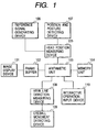
- Fig. 1 is a block diagram showing the basic configuration of the image generation/display apparatus of the embodiment 1.
- an image display device 101 for presenting an image to the operator, is composed for example of a CRT or an LCD.
- a frame buffer 102 stores the image data to be displayed on the image display device 101.
- An arithmetic unit 103 generates image data by executing the procedure stored in a memory unit 104 and controls various devices.
- the image data generated by the arithmetic unit 103 are stored in the frame buffer 102.
- a memory unit 104 stores the procedure of processing of the arithmetic unit 103 and the information required for processing. It also provides a memory area for the calculation required in the processing of the arithmetic unit 103.
- the memory unit 104 stores a control program represented by a flowchart shown in Fig. 3 as will be explained later, data relating to the pattern to be drawn, and data to be employed in the processing.
- a head position measuring device 105 analyzes the signal from a position and posture detecting device 107 and enters the information on the position and posture of the head of the operator, based on a reference signal generation device 106, into the arithmetic unit 103.
- a reference signal generation device 106 generates a signal representing the state of a magnetic field, serving as the reference for the position and posture detecting device 107 and sends this signal to the head position measuring device 105.
- a position and posture detecting device 107 detects the state of the magnetic field resulting from the change in the position and the posture of the head and sends such state to the head position measuring device 105.
- a view line direction measuring device 108 analyzes the signal from an eyeball movement detecting device 109 and sends information on the view line direction of the dominant eye, based on the head, to the arithmetic unit 103.
- An eyeball movement detecting device 109 detects the direction of the dominant eye of the operator by infrared irradiation thereto.
- An interactive operation input device 110 designates the position of the original point of projection, through manipulation by the operator. It can be composed of any device allowing real-time input by the operator, such as a mouse, a keyboard, a dial box, a tracking ball or a three-dimensional position sensor.
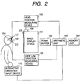
- Fig. 2 is a view showing the schematic arrangement of the devices constituting the image generation/display apparatus of the present embodiment 1.
- the reference signal generating device 106 is fixed on the image display device 101.
- the reference signal generating device 106 may also provided by another method capable of fixing the relative position with respect to the image display device 101.
- the reference signal generating device 106 may be fixed on a support member on which the image display device 101 is fixed.
- the image display device 101 is provided, at the side of the operator, with an image display plane 205, which is observed by the operator through a detecting device support member 204 of spectacle frame shape.
- the position and posture detecting device 107 and the eyeball movement detecting device 109 are fixed, by the detecting device support member 204, on the head of the operator.
- the eyeball movement detecting device 109 is mounted in front of the eyeball of the dominant eye 202 of the operator.
- Fig. 3 is a view showing the detecting device support member 204.
- the position and posture detecting device 107 is mounted at the upper center of the frame, while eyeball movement detecting device 109 is mounted under the frame, at the side of the dominant eye of the operator.
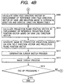
- Figs. 4A and 4B are flowcharts showing the flow of the image generation/display process in the present embodiment 1.
- the process represented by the flowchart is executed by the arithmetic unit 103 according to the information stored in the memory device 104.
- the head position measuring device 105 measures the change in the position of the head of the operator, based on the state of a magnetic field detected by the position and posture detecting device 107 and utilizing, as the reference, the state of the magnetic field indicated by the signal generated by the reference signal generating device 106, and effects conversion (transformation) into a value based on the image display plane 205 of the image display device. This conversion is executed, based on a coordinate system shown in Fig. 5. Since the reference signal generating device 106 is fixed relative to the image display device 101 as already explained in the foregoing with reference to Fig. 2, the position and the posture with reference to the image display plane 205 of the image display device can be calculated by measuring in advance the positional relationship between the image display device 101 and the reference signal generating device 106.
- a next step S402 calculates the viewpoint position 503 of the dominant eye 202 of the operator, utilizing the image display plane 205 of the image display device as reference.
- the relative coordinate values of the viewpoint position 503 with respect to the position of the position and posture detecting device 107 are memorized as offset values, and the viewpoint position 503 is determined by adding these offset values to the coordinate values of the position and posture detecting device 107, determined in the step S401.
- the relationship between the coordinate system of the image display plane 205 of the image display device and the viewpoint position 503 is as shown in Fig. 5.
- a step 403 calculates the view line direction 504, based on the image display plane 205 of the image display device, based on vector information obtained by analyzing the signal from the eyeball movement detecting device 109 by means of the view line direction measuring device 108 and posture information on the head of the operator, determined in the step S401.
- the relationship between the coordinate system of the image display plane 205 of the image display device and the view line direction 504 is as shown in Fig. 5.
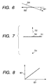
- a next step S404 determines, as the view line deviation angle 601, the angle between the view line direction 504 and the central axis 502 of the image display plane of the image display device, respectively in each of the horizontal and vertical directions of the image display plane of the image display device.
- the view line deviation angle 601 has a horizontal component and a vertical component.
- the relationship among the view line direction 504, the central axis 502 of the image display plane of the image display device and the view line deviation angle 601 is as shown in Fig. 6.
- a next step S405 designates, as the position 703 of the reference projection plane, the center position of the projection plane corresponding to the image display plane 205, in a virtual three-dimensional space to be displayed. Such designation may be achieved by manipulation of the interactive input device 101 by the operator or may be made in a fixed manner in advance.
- a next step S406 designates, in the virtual three-dimensional space to be displayed, the direction of the normal line to the projection plane corresponding to the image display plane 205 as the reference view field direction 702. Such designation may be achieved by manipulation of the interactive input device 101 by the operator or may be made in a fixed manner in advance.
- a next step S407 converts the viewpoint position 503 into a coordinate representation in the virtual three-dimensional space to be displayed, based on the reference projection plane position 703 and the reference view field direction 702 determined in the foregoing steps S405 and S406, and takes such representation as the original point 704 of projection.
- This conversion will be self obvious as the viewpoint position 503 is represented by the coordinate relative to the image plane of the image display device, which in turn corresponds to the projection plane.
- Fig. 7 shows the positional relationship among the reference projection plane position 703, the reference view field direction 702 and the projection original point 704 determined in the foregoing steps S405, S406 and S407.
- a next step S408 calculates the view field deviation angle 801 for each of the horizontal and vertical directions, utilizing a monotone increasing function as shown in Fig. 8 and containing, as variables, the view line deviation angle 601 in the horizontal and vertical directions calculated in the step S404.
- the monotone increasing function need not be a linear function. Also the inclination of the monotone increasing function may be adjusted arbitrarily.
- a step S409 determines a vector of the view field direction 901, by displacing the vector of the reference view field direction 702 determined in the step S406 according to the view field deviation angle 601 determined in the step S408, as shown in Fig. 9.
- the displacement of the direction vector is achieved by applying the horizontal and vertical components of the view field deviation angle to the respective components of the direction vector to be displaced.
- a next step S410 rotates the center position of the projection plane by the view field deviation angle 601 determined in the step S408, about the projection original point 704, as shown in Fig. 10.
- the steps S409 and S410 rotate the position and the direction of the projection plane, about the projection original point 704.
- a step S411 generates an image projected on the projection plane 1002, subjected to geometric conversion, based on the perspective projection method utilizing, as parameters, the position of the projection plane and the view field direction determined in the steps S409 and S410 and the position of the projection original point determined in the step S407.
- the image generation may be made with any known method such as ray trading method or scan line algorithm.
- the generated image data are accumulated in the frame buffer 102.
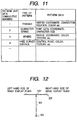
- the three-dimensional pattern data are stored in the memory device 104, in a format as shown in Fig. 11.
- the items of the pattern data in the pattern data list consist of an identification number of the pattern data, the kind of the pattern, the pattern data themselves etc.
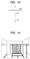
- an observation cursor sketch step in a next step S412 draws an observation point cursor, indicating the observation point, in superposed manner at the observation point 1201 which is the crossing point of the view line direction 504 with the image display plane 205.
- Such cursor is composed of a small pattern or a small character, having a color and a shape easily distinguishable from the background.
- the observation point cursor consists of a yellow cross.
- a next step S413 executes an image display process for displaying the image, accumulated in the frame buffer 102, on the image display device 101.
- a step S414 discriminates whether an instruction for terminating the image generation/display process has been entered from the operator, and, if not, the process is repeated from the step S401, but, if entered, the process is terminated.
- Fig. 14 shows the image obtained in such state.
- the direction of the displayed view field can be displaced vertically and horizontally, and the operator is only required to move the view line in vertical and horizontal directions, without any manipulation of the interactive input device with the hands of the operator.
- the operability of the apparatus can therefore be improved, as the view field direction can be arbitrarily moved merely by the movement of the view line, matching the instinctive action of the operator.
- the operability can be improved further as the manually operated input device can be dispensed with for the movement of the view line.
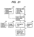
- Fig. 21 shows the basic configuration of an embodiment 2 of the present invention.
- the basic configuration of the embodiment 2 is obtained by eliminating, from that of the embodiment 1, the eyeball movement detecting device 109 and the view line direction measuring device 108.
- Fig. 22 shows the schematic arrangement of the devices of the present embodiment 2.
- the embodiment 2 lacks the eyeball movement detecting device 109 and the view line direction measuring device 108 in the detecting device support member 204.
- the step S403 utilizes the posture of the head determined in the step S401. It is assumed that the operator observes a direction which is in straight front of the head, and such direction in straight front of the head is used as the direction of the view line.
- the direction of the displayed view field can be moved vertically and horizontally in response to corresponding vertical and horizontal movements of the straight front direction of the head of the operator, instead of the movement of the view line thereof, whereby achieved is an effect similar to that in the embodiment 1.
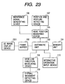
- Fig. 23 shows the basic configuration of an embodiment 3 of the present invention.
- the basic configuration of the embodiment 3 is obtained by replacing, in that of the embodiment 1, the image display device 101 with a 3D image display device 2301.
- the 3D image display device 2301 for showing a 3D image to the operator, is composed of a CRT or an LCD provided with a 3D display mechanism.
- the 3D display may be based on the lenticular system, the time-shared display system by circularly polarized light or the time-shared display system with liquid crystal shutters.
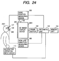
- Fig. 24 shows the schematic arrangement of the devices of the present embodiment 3.
- the arrangement of the detecting devices in the embodiment 3 is obtained, in that of the embodiment 1, by replacing the image display device 101 with the 3D image display device 2301 and the detecting device support member 204 with a detecting device support member 2401 which serves also as 3D observation spectacles provided with a mechanism for stereoscopic observation of the image provided by the 3D image display device 2301.
- Such mechanism for stereoscopic observation depends on the kind of the 3D image display device 2301 selected for the apparatus.
- the support member 2401 is not provided with the stereoscopic observation mechanism in case of the lenticular system.
- the detecting device support member 2401 serving also as the 3D observation spectacles may utilize, for example, stereoscopic observation spectacles 2501 with liquid crystal shutters as shown in Fig. 25 or those 2601 with polarization filters as shown in Fig. 26.
- the flowchart representing the flow of the image generation/display process in the present embodiment 3 is also represented in Figs. 4A and 4B, as in the embodiment 1, except that the step S411 generates two images in consideration of the parallax of the left and right eyes, instead of a single image in the embodiment 1.
- the present invention is applicable also to an image display apparatus which generates and displays a 3D image.
- the embodiments 1 to 3 of the present invention allow to move the direction of the view field to be displayed in the virtual three-dimensional space in response to the movement of the direction of the view line of the operator, thereby dispensing with the manual control of the view field direction by the operator and also providing advantages of reducing the errors in the operation and improving the operability of the apparatus, by an instinct-matching operation that the direction of the view field in the three-dimensional space is moved in the direction of movement of the view line of the operator.
- the position and the posture of the head of the operator are determined by the data from a position and posture detecting device mounted on the head of the operator. Also a distance vector from the center of measurement of the head position and posture measuring device to the optical center of the eyeball is measured in advance, and the measured position vector and the above-mentioned distance vector are synthesized to determine the optical center of the eyeball, namely the position of the viewpoint. Also the head posture and the viewpoint position mentioned above are converted into geometrical representation based on the image display plane of the image display device.
- the amount of rotation of the eyeball is measured by an eyeball movement measuring device.
- Such amount of rotation does not necessarily represent the correct angle of rotation, because of the personal fluctuation in the shape of the eyeball and in the state of mounting of the device, but is merely considered as a value approximately proportional to the rotation angle.
- the following calibrating operation is executed in order to convert such amount of rotation into a correct rotation angle.
- a right direction reference index on the image display plane, in a position on a horizontal plane passing through the viewpoint position and in a direction rotated, about the viewpoint position, to the right by a specified angle from the straight front direction of the head. Then the rotation amount of the eyeball, measured by the eyeball movement measuring device when the operator watches the right direction reference index, is registered as a right reference rotation amount.
- a left direction reference index on the image display plane, in a position on a horizontal plane passing through the viewpoint position and in a direction rotated, about the viewpoint position, to the left by a specified angle from the straight front direction of the head. Then the rotation amount of the eyeball, measured by the eyeball movement measuring device when the operator watches the left direction reference index, is registered as a left reference rotation amount.
- the ratio of the difference between the right and left reference rotation amounts to the difference between the right and left reference angles is set as a first correcting parameter or "correction coefficient".
- the rotation amount obtained from the eyeball movement measuring device is multiplied by the correction coefficient and the zero point offset is added to the obtained result.
- the rotation amount in the unknown unit is converted into a value in the unit of degrees, representing the rotation angle from the front direction of the head.
- This rotation angle is used for calculating a local view line direction vector, taking the head posture as reference.
- This view line direction vector and the viewpoint position vector mentioned above are the target information to be obtained by the view line information input apparatus of the present embodiment.
- the view line information input apparatus of the present embodiment may further execute, by the same central processing unit, any information processing utilizing the view line direction vector and the viewpoint position vector obtained in the above-explained manner.
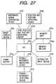
- Fig. 27 is a block diagram showing the basic configuration of the view line information input apparatus of the embodiment 4.
- an image display device 2701 for presenting an arbitrary pattern, image or character to the operator, is composed for example of a CRT, an LCD, a PDP, an EL display or a fluorescent tube display.
- a frame buffer 2702 stores the image data to be displayed on the image display device 2701.
- a central processing unit 2703 executes a correcting operation and processes relating to the generation of the view line information, according to a procedure stored in a memory unit 2704, and also controls various devices. It also generates the image data to be displayed on the image display device 2701 and stores the image data in the frame buffer 2702. The central processing unit 2703 may also execute any other processes utilizing the view line information.
- a memory unit 2704 stores, in a memory medium 2704a, the procedure of processing of the central processing unit 2703 and information required for such processing, and is also used as a memory area for the calculation required in the processing of the central processing unit 2703.
- the memory medium 2704a stores a control program represented in Figs. 29A and 29B and data required in other processes.
- An interactive input device 2705 to be used by the operator for entering instructions for controlling the flow of the control program represented by the flowcharts in Figs. 29A and 29B, is composed for example of a mouse, a keyboard or switches.
- a head position and posture measuring device 2706 analyzes the signal from a position and posture detecting device 2708 and enters the information on the position and posture of the head of the operator, based on a reference signal generation device 2707, into the central processing unit 2703.
- a reference signal generation device 2707 generates a signal to be used as a reference in the position and posture detecting device 2708.
- a position and posture detecting device 2708 detects the position and the posture of the head.
- An eyeball movement measuring device 2709 analyzes a signal from an eyeball movement detecting device 2710 and supplies the central processing unit 2703 with rotation amount information proportional to the rotation angle of the eyeball.
- An eyeball movement detecting device 2710 detects information for measuring the rotational movement of the eyeball of the operator, and is composed of a point light source illuminating the surface of the cornea and an image sensor for receiving the image of the eyeball. It may also be composed of electrodes and a voltmeter for measuring the potential of an eye muscle.
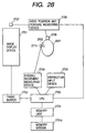
- Fig. 28 is a view showing the schematic arrangement of the devices constituting the views line information input apparatus of the present embodiment 4.
- the reference signal generating device 2707 is fixed on the image display device 2701.
- the reference signal generating device 2707 may also be provided by another method capable of fixing the relative position with respect to the image display device 2701.
- the reference signal generating device 2707 may be fixed on a support member on which the image display device 2701 is fixed. Otherwise, the reference signal generating device 2707 may be fixed on a support member placed a floor, on which placed is a support member fixedly supporting the image display device 2701.
- the position and posture detecting device 2708 and the eyeball movement detecting device 2710 are fixed, by a support member of spectacle frame shape, on the head 2801 of the operator.
- the eyeball movement detecting device 2710 is mounted in front of the eyeball of the eyeball 2802 of the operator.
- the support member may also be provided with a mechanism for separating the left and right images, for achieving stereoscopic observation of the image display device 2701, such as circularly polarizing filters or liquid crystal shutter mechanisms.
- Other devices may be provided in suitable arbitrary positions.
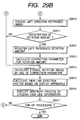
- FIGs. 29A and 29B are flowcharts showing the flow of the view line information input process in the present embodiment 4. Now the details of the process will be step by step explained in the following.
- the first one is a coordinate transformation, representing the relative posture of the head 2801 of the operator, based on the position and posture detecting device 2708.
- the second parameter is a distance vector from the center of measurement of the position and posture detecting device 2708 to the optical center of the eyeball, measured by the information from the position and posture detecting device 2708.
- the third parameter is a coordinate transformation representing the relative posture of the reference signal generating device 2707, based on the image plane of the image display device 2701.
- the head position and posture measuring device 2706 measures the position and the posture of the position and posture detecting device 2708, based on the coordinate system of the reference signal generating device 2707.
- the coordinate transformation, constituting the pre-measured first parameter is synthesized with the measured posture of the position and posture detecting device 2708 to determine the posture of the head, based on the reference signal generating device 2707. Then the coordinate transformation constituting the above-mentioned pre-measured third parameter is applied to thus determined head posture to determine the posture of the head, based on the image plane of the image display device 2701.
- a step S2902 synthesizes the position vector of the position and posture detecting device 2708, measured in the step S2901 based on the coordinate system of the reference signal generating device 2707, with the distance vector constituting the above-mentioned pre-measured second parameter, thereby determining the optical center of the eyeball based on the coordinate system of the reference signal generating device 2707, namely the viewpoint position.
- This position is further subjected to the coordinate transformation constituting the aforementioned pre-measured third parameter to determine the viewpoint position 3007, based on the image plane of the image display device 2701.
- a next step S2903 analyzes the signal from the eyeball movement detecting device 2710 by the eyeball movement measuring device 2709, thereby measuring the rotation amount of the eyeball.
- the rotation amount of the eyeball measured by the eyeball movement measuring device 2709 does not necessary represent the correct rotation angle, because of the personal fluctuation in the shape of the eyeball and in the state of mounting, but is approximately linearly related with the rotation angle. Consequently it has to be corrected to the correct rotation angle.
- a parameter required for this purpose is called “correcting parameter”, and an operation of setting the correcting parameter is called “calibrating operation”.
- the correcting parameter will be explained in more details later.
- the calculation of the correcting parameters requires two additional parameters, namely a "right reference rotation amount” and a “left reference rotation amount”, which will also be explained later.
- a next step S2904 discriminates whether a calibrating operation is required, and, if not, the sequence jumps to a step S2914, but, if required, the sequence proceeds to a step S2905.
- a step S2905 discriminates whether the sequence branches to a process for registering the right reference rotation amount, according to whether a distinctive instruction is given therefor by the operator through the interactive input device 2705.
- the sequence proceeds to a step S2906 in case such process for registering the right reference rotation amount is to be executed, but it proceeds to a step S2909 in case such process is not to be executed.
- a step S2906 displays a marker index, namely a right direction reference index 3004, in a position on the image display device 2701 and at a direction which is in a plane passing through the viewpoint position 3007 determined in the step S2902 and defined by the head front direction 3001 and the head horizontal direction 3002 determined in the step S2901 and which is rotated, from the head front direction 3001, to the right by a predetermined angle, namely by the right reference angle 3003 starting from the viewpoint position 3007.
- a marker index namely a right direction reference index 3004
- a next step S2907 discriminates whether the eyeball rotation amount measured in the step S2903 is to be registered as the right reference rotation amount.
- the conditions for this discrimination are that the operator watches the right direction reference index 3004 displayed in the step S2906 and that a distinctive instruction is given by the operator through the interactive input device 2705.
- a next step S2908 registers, as the right reference rotation amount, the eyeball rotation amount when the operator watches the right direction reference index 3004 displayed on the image display device 2701 in the step S2906, Then the sequence proceeds to a step S2909.
- a step S2909 discriminates whether the sequence branches to a process for registering the left reference rotation amount, according to whether a distinctive instruction is given therefor by the operator through the interactive input device 2705.
- a step S2910 displays a marker index, namely a left direction reference index 3006, in a position on the image display device 2701 and at a direction which is in a plane passing through the viewpoint position 3007 determined in the step S2902 and defined by the head front direction 3001 and the head horizontal direction 3002 determined in the step S2901 and which is rotated, from the head front direction 3001, to the right by a predetermined angle, namely by the left reference angle 3005 starting from the viewpoint position 3007.
- a next step S2911 discriminates whether the eyeball rotation amount measured in the step S2903 is to be registered as the left reference rotation amount.
- the conditions for this discrimination are that the operator watches the left direction reference index 3006 displayed in the step S2910 and that a distinctive instruction is given by the operator through the interactive input device 2705.
- a next step S2912 registers, as the left reference rotation amount, the eyeball rotation amount when the operator watches the left direction reference index 3006 displayed on the image display device 2701 in the step S2910.
- a next step S2913 calculates the correcting parameters, utilizing the right reference rotation amount registered in the step S2908 and the left reference rotation amount registered in the step S2912.
- the correcting parameters include the "correction coefficient” and the "zero point offset".
- the "correction coefficient” is obtained by dividing the difference of the right and left reference rotation amounts with the difference of the right reference angle 3003 and the left reference angle 3005.
- the "zero point offset” is obtained by subtracting the product of the right reference rotation amount and the correction coefficient from the reference angle 3003.
- a step S2914 converts the eyeball rotation amount, measured by the eyeball movement measuring device 2709 in the step S2903, into an eyeball rotation angle based on the head of the operator, utilizing the two correcting parameters, namely the correction coefficient and the zero point offset, determined in the step S2913. This conversion is achieved by adding the zero point offset to the product obtained by multiplying the eyeball rotation amount with the correction coefficient.
- a next step S2915 applies the coordinate transformation, constituting the aforementioned pre-measured third parameter, to the coordinate transformation representing the eyeball rotation amount determined in the step S2914, thereby calculating the view line direction vector 3008 based on the image display device 2701.
- the viewpoint position vector 3007 determined in the step S2901 and the view line direction vector 3008 determined in the step S2915 are the target information desired in the view line information input apparatus of the present embodiment.
- a step S2916 executes an arbitrary process utilizing the viewpoint position vector determined in the step S2901 and the view line direction vector determined in the step S2915.
- the simplest example of such process is to display, at the crossing point of the view line 3007 with the image display plane of the image display device 2701, an index mark indicating the point watched by the operator.
- a step S2917 discriminates whether the process is to be terminated, and, if not, the sequence returns to the step S2901 to repeat the process.
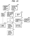
- a fifth embodiment of the present invention of which basic configuration is obtained by adding, as shown in Fig. 31, an information communicating device 3101 and an information processing device 3102 to the basic configuration of the fourth embodiment.
- the information communicating device 3101 transmits, by an arbitrary communication format such as Ethernet, RS232C, telephone line or ISDN, the view line information of the operator obtained by the fourth embodiment, namely the viewpoint position vector 3007 and the view line direction vector 3008 based on the image display device 2701, to an arbitrary information processing device 3102, which in response executes an arbitrary process, utilizing the view line information transmitted from the information communicating device 3101.
- an arbitrary communication format such as Ethernet, RS232C, telephone line or ISDN
- the view line information of the operator obtained by the fourth embodiment namely the viewpoint position vector 3007 and the view line direction vector 3008 based on the image display device 2701
- an arbitrary information processing device 3102 which in response executes an arbitrary process, utilizing the view line information transmitted from the information communicating device 3101.
- FIG. 29A and 29B The flowchart representing the flow of the view line information input process in the present fifth embodiment is also represented by Figs. 29A and 29B, as in the case of the fourth embodiment, and the details of all the process steps are same as those in the fourth embodiment, except however for the step S2916.
- step S2916 in the fifth embodiment is approximately same as that in the fourth embodiment, but it also includes a procedure of transmitting the viewpoint position vector 3007 and the view line direction vector 3008 to the information processing device 3102 through the information communicating device 3101.
- the fourth and fifth embodiments allow to display an index mark, necessary for the calibrating operation, in an appropriate position on the image display plane, based on the position and the posture of the head of the operator. Consequently the calibrating operation can be executed while the view line information entered from the view line information input device is utilized in another information processing device. Thus correct calibration can be conducted at any time, without causing the trouble of fixing the head of the operator.
- the present invention is applicable not only to a system consisting of plural equipment but also to an apparatus consisting of a single equipment. It is naturally applicable also to a case where the present invention is executed by the supply of a program to a system or an apparatus.
- a memory medium storing a program relating to the present invention constitutes the present invention, and, the system or the apparatus functions in a predetermined manner by fetching such program from the memory medium into such system or apparatus.
- the view line direction measuring device measures such movement and the direction of the view field is moved, within the space, in the moving direction of the view line according to the result of calculation by the arithmetic operation unit.
Landscapes
- Engineering & Computer Science (AREA)
- Multimedia (AREA)
- Signal Processing (AREA)
- General Engineering & Computer Science (AREA)
- Theoretical Computer Science (AREA)
- Human Computer Interaction (AREA)
- Physics & Mathematics (AREA)
- General Physics & Mathematics (AREA)
- Processing Or Creating Images (AREA)
- Position Input By Displaying (AREA)
- Controls And Circuits For Display Device (AREA)
- Image Processing (AREA)
Applications Claiming Priority (6)
| Application Number | Priority Date | Filing Date | Title |
|---|---|---|---|
| JP31949996A JPH10161802A (ja) | 1996-11-29 | 1996-11-29 | 画像表示方法及び装置 |
| JP31949996 | 1996-11-29 | ||
| JP319499/96 | 1996-11-29 | ||
| JP8324456A JPH10161800A (ja) | 1996-12-04 | 1996-12-04 | 視線情報入力方法及び装置並びに記憶媒体 |
| JP324456/96 | 1996-12-04 | ||
| JP32445696 | 1996-12-04 |
Publications (3)
| Publication Number | Publication Date |
|---|---|
| EP0845737A2 true EP0845737A2 (de) | 1998-06-03 |
| EP0845737A3 EP0845737A3 (de) | 1998-06-10 |
| EP0845737B1 EP0845737B1 (de) | 2003-11-05 |
Family
ID=26569741
Family Applications (1)
| Application Number | Title | Priority Date | Filing Date |
|---|---|---|---|
| EP97120884A Expired - Lifetime EP0845737B1 (de) | 1996-11-29 | 1997-11-27 | Bildanzeigeverfahren und -gerät |
Country Status (3)
| Country | Link |
|---|---|
| US (1) | US6157382A (de) |
| EP (1) | EP0845737B1 (de) |
| DE (1) | DE69725953T2 (de) |
Cited By (7)
| Publication number | Priority date | Publication date | Assignee | Title |
|---|---|---|---|---|
| WO2004036503A1 (en) * | 2002-10-17 | 2004-04-29 | Koninklijke Philips Electronics N.V. | Method and system for producing a pseudo three-dimensional display utilizing a two-dimensional display device |
| EP2075761A1 (de) * | 2007-12-31 | 2009-07-01 | HTC Corporation | Verfahren und Gerät für die Anpassung des Ausgangsrahmens |
| EP2116919A1 (de) * | 2008-05-09 | 2009-11-11 | MBDA UK Limited | Anzeige für dreidimensionale Objekte |
| WO2009136207A1 (en) * | 2008-05-09 | 2009-11-12 | Mbda Uk Limited | Display of 3-dimensional objects |
| WO2011044936A1 (en) * | 2009-10-14 | 2011-04-21 | Nokia Corporation | Autostereoscopic rendering and display apparatus |
| CN103581654A (zh) * | 2012-07-30 | 2014-02-12 | 联想(北京)有限公司 | 一种信息处理方法 |
| EP2886041A1 (de) * | 2013-12-17 | 2015-06-24 | ESSILOR INTERNATIONAL (Compagnie Générale d'Optique) | Verfahren zur Kalibrierung einer am Kopf montierten Augenverfolgungsvorrichtung |
Families Citing this family (13)
| Publication number | Priority date | Publication date | Assignee | Title |
|---|---|---|---|---|
| JPH11155152A (ja) * | 1997-11-21 | 1999-06-08 | Canon Inc | 三次元形状情報入力方法及び装置及び画像入力装置 |
| JP3943975B2 (ja) | 2002-03-29 | 2007-07-11 | キヤノン株式会社 | 情報処理方法および装置 |
| KR100491432B1 (ko) * | 2002-11-06 | 2005-05-25 | 주식회사 유씨티코리아 | 멀티모달 사용자 인터페이스를 이용한 대화형 전시시스템 |
| US8159526B2 (en) * | 2004-09-17 | 2012-04-17 | Seiko Epson Corporation | Stereoscopic image display system |
| JP4926826B2 (ja) * | 2007-05-25 | 2012-05-09 | キヤノン株式会社 | 情報処理方法および情報処理装置 |
| JP2010086336A (ja) * | 2008-09-30 | 2010-04-15 | Fujitsu Ltd | 画像制御装置、画像制御プログラムおよび画像制御方法 |
| FR2972339B1 (fr) * | 2011-03-11 | 2013-04-19 | Essilor Int | Procede de determination de l'oeil directeur |
| FR2972911B1 (fr) * | 2011-03-25 | 2013-04-05 | Essilor Int | Dispositif et procede de determination de l'oeil directeur d'un patient |
| US20120293528A1 (en) * | 2011-05-18 | 2012-11-22 | Larsen Eric J | Method and apparatus for rendering a paper representation on an electronic display |
| US20130007672A1 (en) * | 2011-06-28 | 2013-01-03 | Google Inc. | Methods and Systems for Correlating Head Movement with Items Displayed on a User Interface |
| US9727132B2 (en) * | 2011-07-01 | 2017-08-08 | Microsoft Technology Licensing, Llc | Multi-visor: managing applications in augmented reality environments |
| US9292089B1 (en) * | 2011-08-24 | 2016-03-22 | Amazon Technologies, Inc. | Gestural object selection |
| JP6326219B2 (ja) | 2013-11-26 | 2018-05-16 | 圭祐 戸田 | 表示装置および表示方法 |
Family Cites Families (5)
| Publication number | Priority date | Publication date | Assignee | Title |
|---|---|---|---|---|
| JP3318680B2 (ja) * | 1992-04-28 | 2002-08-26 | サン・マイクロシステムズ・インコーポレーテッド | 画像生成方法及び画像生成装置 |
| US5528735A (en) * | 1993-03-23 | 1996-06-18 | Silicon Graphics Inc. | Method and apparatus for displaying data within a three-dimensional information landscape |
| US5594842A (en) * | 1994-09-06 | 1997-01-14 | The Research Foundation Of State University Of New York | Apparatus and method for real-time volume visualization |
| JP4272711B2 (ja) * | 1995-05-15 | 2009-06-03 | キヤノン株式会社 | 画像生成方法及び装置 |
| US6081271A (en) * | 1997-05-23 | 2000-06-27 | International Business Machines Corporation | Determining view point on objects automatically in three-dimensional workspace from other environmental objects in a three-dimensional workspace |
-
1997
- 1997-11-24 US US08/976,514 patent/US6157382A/en not_active Expired - Lifetime
- 1997-11-27 EP EP97120884A patent/EP0845737B1/de not_active Expired - Lifetime
- 1997-11-27 DE DE69725953T patent/DE69725953T2/de not_active Expired - Lifetime
Cited By (14)
| Publication number | Priority date | Publication date | Assignee | Title |
|---|---|---|---|---|
| WO2004036503A1 (en) * | 2002-10-17 | 2004-04-29 | Koninklijke Philips Electronics N.V. | Method and system for producing a pseudo three-dimensional display utilizing a two-dimensional display device |
| EP2075761A1 (de) * | 2007-12-31 | 2009-07-01 | HTC Corporation | Verfahren und Gerät für die Anpassung des Ausgangsrahmens |
| EP2116919A1 (de) * | 2008-05-09 | 2009-11-11 | MBDA UK Limited | Anzeige für dreidimensionale Objekte |
| WO2009136207A1 (en) * | 2008-05-09 | 2009-11-12 | Mbda Uk Limited | Display of 3-dimensional objects |
| US8970478B2 (en) | 2009-10-14 | 2015-03-03 | Nokia Corporation | Autostereoscopic rendering and display apparatus |
| WO2011044936A1 (en) * | 2009-10-14 | 2011-04-21 | Nokia Corporation | Autostereoscopic rendering and display apparatus |
| CN102640502A (zh) * | 2009-10-14 | 2012-08-15 | 诺基亚公司 | 自动立体渲染和显示装置 |
| RU2524834C2 (ru) * | 2009-10-14 | 2014-08-10 | Нокиа Корпорейшн | Устройство для автостереоскопического рендеринга и отображения |
| CN103581654A (zh) * | 2012-07-30 | 2014-02-12 | 联想(北京)有限公司 | 一种信息处理方法 |
| EP2886041A1 (de) * | 2013-12-17 | 2015-06-24 | ESSILOR INTERNATIONAL (Compagnie Générale d'Optique) | Verfahren zur Kalibrierung einer am Kopf montierten Augenverfolgungsvorrichtung |
| WO2015091577A1 (en) * | 2013-12-17 | 2015-06-25 | Essilor International (Compagnie Generale D'optique) | Method for calibrating a head-mounted eye tracking device |
| CN105828702A (zh) * | 2013-12-17 | 2016-08-03 | 埃西勒国际通用光学公司 | 用于校准头戴式眼睛跟踪装置的方法 |
| US10307053B2 (en) | 2013-12-17 | 2019-06-04 | Essilor International | Method for calibrating a head-mounted eye tracking device |
| CN105828702B (zh) * | 2013-12-17 | 2019-07-19 | 依视路国际公司 | 用于校准头戴式眼睛跟踪装置的方法 |
Also Published As
| Publication number | Publication date |
|---|---|
| DE69725953D1 (de) | 2003-12-11 |
| US6157382A (en) | 2000-12-05 |
| DE69725953T2 (de) | 2004-09-02 |
| EP0845737A3 (de) | 1998-06-10 |
| EP0845737B1 (de) | 2003-11-05 |
Similar Documents
| Publication | Publication Date | Title |
|---|---|---|
| US6157382A (en) | Image display method and apparatus therefor | |
| US6753828B2 (en) | System and method for calibrating a stereo optical see-through head-mounted display system for augmented reality | |
| US20020105484A1 (en) | System and method for calibrating a monocular optical see-through head-mounted display system for augmented reality | |
| JP7854048B2 (ja) | 表示機器のための位置合わせ方法及び位置合わせ装置、車載表示システム | |
| US20260095563A1 (en) | Methods and systems for multiple access to a single hardware data stream | |
| EP0769881B1 (de) | Verfahren zur Kalibrierung einer Anzeigeeinheit, die dem Beobachter folgt | |
| JP4888579B2 (ja) | 視機能検査装置 | |
| JP3717653B2 (ja) | 頭部搭載型画像表示装置 | |
| Genc et al. | Optical see-through HMD calibration: A stereo method validated with a video see-through system | |
| US20100315414A1 (en) | Display of 3-dimensional objects | |
| JP2010259605A (ja) | 視線測定装置および視線測定プログラム | |
| JPH10333094A (ja) | 立体画像表示装置、立体画像表示方法及び記録媒体 | |
| JP5417417B2 (ja) | 視機能検査装置 | |
| Baratoff et al. | Interactive multi-marker calibration for augmented reality applications | |
| KR20080100984A (ko) | 3차원 영상 디스플레이 방법 및 장치 | |
| JP2011015721A (ja) | 立体映像表示装置の立体スケール像形成装置 | |
| JP2011153995A (ja) | 立体映像表示装置の立体ノギス像形成装置およびプログラム | |
| Ikits et al. | A comprehensive calibration and registration procedure for the visual haptic workbench | |
| TWI790640B (zh) | 擴增實境顯示裝置與方法 | |
| EP4715530A1 (de) | Systeme und verfahren zur messung der blickpunkttreue in einer kopfmontierten anzeige | |
| Cattari et al. | Optical see-through head-mounted display with mitigated parallax-related registration errors: a user study validation | |
| JPH10161802A (ja) | 画像表示方法及び装置 | |
| JP3546756B2 (ja) | 空間座標入力装置 | |
| Schinko et al. | Building a Driving Simulator with Parallax Barrier Displays. | |
| JP2000330714A (ja) | 空間図形入力装置 |
Legal Events
| Date | Code | Title | Description |
|---|---|---|---|
| PUAI | Public reference made under article 153(3) epc to a published international application that has entered the european phase |
Free format text: ORIGINAL CODE: 0009012 |
|
| PUAL | Search report despatched |
Free format text: ORIGINAL CODE: 0009013 |
|
| AK | Designated contracting states |
Kind code of ref document: A2 Designated state(s): DE FR GB IT NL |
|
| AX | Request for extension of the european patent |
Free format text: AL;LT;LV;MK;RO;SI |
|
| AK | Designated contracting states |
Kind code of ref document: A3 Designated state(s): AT BE CH DE DK ES FI FR GB GR IE IT LI LU MC NL PT SE |
|
| AX | Request for extension of the european patent |
Free format text: AL;LT;LV;MK;RO;SI |
|
| 17P | Request for examination filed |
Effective date: 19981027 |
|
| AKX | Designation fees paid |
Free format text: DE FR GB IT NL |
|
| RBV | Designated contracting states (corrected) |
Designated state(s): DE FR GB IT NL |
|
| 17Q | First examination report despatched |
Effective date: 20010119 |
|
| GRAH | Despatch of communication of intention to grant a patent |
Free format text: ORIGINAL CODE: EPIDOS IGRA |
|
| GRAS | Grant fee paid |
Free format text: ORIGINAL CODE: EPIDOSNIGR3 |
|
| GRAA | (expected) grant |
Free format text: ORIGINAL CODE: 0009210 |
|
| AK | Designated contracting states |
Kind code of ref document: B1 Designated state(s): DE FR GB IT NL |
|
| PG25 | Lapsed in a contracting state [announced via postgrant information from national office to epo] |
Ref country code: NL Free format text: LAPSE BECAUSE OF FAILURE TO SUBMIT A TRANSLATION OF THE DESCRIPTION OR TO PAY THE FEE WITHIN THE PRESCRIBED TIME-LIMIT Effective date: 20031105 Ref country code: IT Free format text: LAPSE BECAUSE OF FAILURE TO SUBMIT A TRANSLATION OF THE DESCRIPTION OR TO PAY THE FEE WITHIN THE PRE;WARNING: LAPSES OF ITALIAN PATENTS WITH EFFECTIVE DATE BEFORE 2007 MAY HAVE OCCURRED AT ANY TIME BEFORE 2007. THE CORRECT EFFECTIVE DATE MAY BE DIFFERENT FROM THE ONE RECORDED.SCRIBED TIME-LIMIT Effective date: 20031105 |
|
| REG | Reference to a national code |
Ref country code: GB Ref legal event code: FG4D |
|
| REF | Corresponds to: |
Ref document number: 69725953 Country of ref document: DE Date of ref document: 20031211 Kind code of ref document: P |
|
| NLV1 | Nl: lapsed or annulled due to failure to fulfill the requirements of art. 29p and 29m of the patents act | ||
| ET | Fr: translation filed | ||
| PLBE | No opposition filed within time limit |
Free format text: ORIGINAL CODE: 0009261 |
|
| STAA | Information on the status of an ep patent application or granted ep patent |
Free format text: STATUS: NO OPPOSITION FILED WITHIN TIME LIMIT |
|
| 26N | No opposition filed |
Effective date: 20040806 |
|
| PGFP | Annual fee paid to national office [announced via postgrant information from national office to epo] |
Ref country code: GB Payment date: 20141124 Year of fee payment: 18 Ref country code: DE Payment date: 20141130 Year of fee payment: 18 |
|
| PGFP | Annual fee paid to national office [announced via postgrant information from national office to epo] |
Ref country code: FR Payment date: 20141126 Year of fee payment: 18 |
|
| REG | Reference to a national code |
Ref country code: DE Ref legal event code: R119 Ref document number: 69725953 Country of ref document: DE |
|
| GBPC | Gb: european patent ceased through non-payment of renewal fee |
Effective date: 20151127 |
|
| REG | Reference to a national code |
Ref country code: FR Ref legal event code: ST Effective date: 20160729 |
|
| PG25 | Lapsed in a contracting state [announced via postgrant information from national office to epo] |
Ref country code: DE Free format text: LAPSE BECAUSE OF NON-PAYMENT OF DUE FEES Effective date: 20160601 Ref country code: GB Free format text: LAPSE BECAUSE OF NON-PAYMENT OF DUE FEES Effective date: 20151127 |
|
| PG25 | Lapsed in a contracting state [announced via postgrant information from national office to epo] |
Ref country code: FR Free format text: LAPSE BECAUSE OF NON-PAYMENT OF DUE FEES Effective date: 20151130 |