EP2075761A1 - Verfahren und Gerät für die Anpassung des Ausgangsrahmens - Google Patents
Verfahren und Gerät für die Anpassung des Ausgangsrahmens Download PDFInfo
- Publication number
- EP2075761A1 EP2075761A1 EP08022428A EP08022428A EP2075761A1 EP 2075761 A1 EP2075761 A1 EP 2075761A1 EP 08022428 A EP08022428 A EP 08022428A EP 08022428 A EP08022428 A EP 08022428A EP 2075761 A1 EP2075761 A1 EP 2075761A1
- Authority
- EP
- European Patent Office
- Prior art keywords
- output frame
- user
- display
- relative position
- adjusting
- Prior art date
- Legal status (The legal status is an assumption and is not a legal conclusion. Google has not performed a legal analysis and makes no representation as to the accuracy of the status listed.)
- Granted
Links
Images


Classifications
-
- G—PHYSICS
- G06—COMPUTING OR CALCULATING; COUNTING
- G06F—ELECTRIC DIGITAL DATA PROCESSING
- G06F3/00—Input arrangements for transferring data to be processed into a form capable of being handled by the computer; Output arrangements for transferring data from processing unit to output unit, e.g. interface arrangements
- G06F3/01—Input arrangements or combined input and output arrangements for interaction between user and computer
- G06F3/011—Arrangements for interaction with the human body, e.g. for user immersion in virtual reality
-
- G—PHYSICS
- G06—COMPUTING OR CALCULATING; COUNTING
- G06T—IMAGE DATA PROCESSING OR GENERATION, IN GENERAL
- G06T7/00—Image analysis
- G06T7/70—Determining position or orientation of objects or cameras
- G06T7/73—Determining position or orientation of objects or cameras using feature-based methods
- G06T7/74—Determining position or orientation of objects or cameras using feature-based methods involving reference images or patches
-
- G—PHYSICS
- G06—COMPUTING OR CALCULATING; COUNTING
- G06T—IMAGE DATA PROCESSING OR GENERATION, IN GENERAL
- G06T2207/00—Indexing scheme for image analysis or image enhancement
- G06T2207/30—Subject of image; Context of image processing
- G06T2207/30196—Human being; Person
- G06T2207/30201—Face
Definitions
- the present invention is related to a method and a device for outputting a frame, and particularly to a method and a device capable of automatically adjusting the output frame according to a user's position.
- CTR cathode ray tube
- display result of a display most directly influences the impression the user has after using an electronic product.
- the user can adjust parameters of the display, such as resolution, contrast and luminance, to obtain a better output frame according to his/her own habits.
- parameters of the display such as resolution, contrast and luminance
- current electronic products usually cannot automatically adjust the frame dynamically according to the user's current position. For example, generally, the size of the words displayed on the frame is fixed, and therefore when the user keeps a farther distance from the display, the user very possibly cannot clearly see the contents of the frame because the words on the frame are too small.
- the frame is also affected and limited by gray scale inversion of the LCD such that when viewed at certain angles the user would see frames like those in black and white inversion.
- barriers or micro-prisms are disposed therein to limit the left eye of the user to view pixels on the left and the right eye of the user to view pixels on the right so as to achieve the three-dimensional display effect. Therefore, when the user views a 3D display, the viewing is limited by view angles. When the user is located at a dead view angle, the left eye of the user can only see the pixels on the right, and the right eye of the user can only see the pixels on the left. At this moment, the frame seen by the user is broken.
- the display function is very easily limited and will display many display results that are unacceptable to viewers. Since the user cannot see the displayed frames clearly, more negative impressions of the electronic products are likely to be formed.
- the present disclosure provides a method for adjusting an output frame, which adjusts the output frame correspondingly according to a position where a user views a display so as to generate a better output result.
- the present disclosure provides a device for adjusting an output frame. After detecting a relative position between a user and a display, the device automatically adjusts the output frame according to the relative position so as to render it more convenient for the user to view the output frame.
- the present disclosure provides a method for adjusting an output frame, which is suitable for an electronic device with a display.
- a relative position between the user and the display is obtained first.
- the output frame of the display is correspondingly adjusted according to the relative position.
- the step of obtaining the relative position between the user and the display includes capturing an input image including the user, obtaining a facial feature of the user from the input image, and then determining the relative position between the user and the display according to the facial feature.
- the facial feature can be eye positions, a nose position, a mouth position or a facial outline of the user.
- the step of determining the relative position according to the facial feature includes determining a rotating angle of the user relative to the display according to an angle formed by a connected line of the eye positions and a rotating reference line preset on the input image.
- the step of determining the relative position according to the facial feature includes determining a shift of the user relative to the display according to a shift reference point on the input image and a position of the facial feature in the input image.
- the step of determining the relative position according to the facial feature includes obtaining a size and proportion of the facial feature relative to the input image and comparing the size and proportion with a proportion reference value so as to determine a distance between the user and the display.
- the step of correspondingly adjusting the output frame according to the relative position includes scaling the output frame, rotating the output frame, shifting the output frame, adjusting colors of the output frame, changing contents of the output frame and adjusting pixels of the output frame to optimize display result of the output frame.
- the present disclosure provides a device for adjusting an output frame.
- the device for adjusting the output frame includes a display, a user detecting module, a relative position obtaining module and an image processing module.
- the display displays the output frame.
- the user detecting module obtains an input information related to the user.
- the relative position obtaining module is connected to the user detecting module and determines the relative position between the user and the display with the input information.
- the image processing module is connected to the display and the relative position obtaining module and adjusts the output frame correspondingly according to the relative position between the user and the display so as to control the display to display the adjusted output frame.
- the user detecting module is an image capturing device and captures an input image including the user as the input information.
- the relative position obtaining module obtains a facial feature of the user from the input image captured by the user detecting module and determines the relative position between the user and the display according to the facial feature.
- the user detecting module can be an image capturing device.
- the facial feature can be eye positions, a nose position, a mouth position or a facial outline of the user.
- the relative position obtaining module determines a rotating angle of the user relative to the display according to an angle formed by a connected line of the eye positions and a rotating reference line on the input image.
- the relative position obtaining module determines a shift of the user relative to the display according to a shift reference point on the input image and a position of the facial feature in the input image.
- the relative position obtaining module obtains a size and proportion of the facial feature relative to the input image and compares a proportion reference value and the size and proportion to determine a distance between the user and the display.
- the image processing module scales the output frame, rotates the output frame, shifts the output frame, adjusts colors of the output frame, changes contents of the output frame or adjusts pixels of the output frame according to the relative position so as to optimize display result of the output frame.
- the output frame is adjusted correspondingly according to the relative position between the user and the display when the user is viewing the display.
- the display of the present disclosure outputs the frame most suitable for the user to view in the current position such that the user can view the contents of the output frame with a more relaxing manner and enjoy the best display result at the same time.
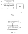
- FIG. 1 is a block diagram of a device for adjusting an output frame according to an embodiment of the present disclosure.
- FIG. 2 is a flowchart showing a method for adjusting an output frame according to an embodiment of the present disclosure.
- FIG. 3 is a flowchart of obtaining a relative position according to an embodiment of the disclosure.
- FIGs. 4 , 5 , 6 , 7 , 8 , 9, and 10 are schematic views of an image including a user according to an embodiment of the present disclosure.
- the present disclosure is a method and a device for adjusting an output frame which are developed from said viewpoint. In order to render the present disclosure more comprehensible, embodiments are described below as the examples to prove that the disclosure can actually be realized.
- FIG. 1 is a block diagram of a device for adjusting an output frame according to an embodiment of the present disclosure.
- a device 100 for adjusting an output frame includes a display 110, a user detecting module 120, a relative position obtaining module 130 and an image processing module 140.
- the display 110 displays the output frame.
- the user detecting module 120 receives an input information related to the user.
- the relative position obtaining module 130 is connected to the user detecting module 120 and determines a relative position between the user and the display 110 with the input information received by the user detecting module 120.
- the image processing module 140 is simultaneously connected to the display 110 and the relative position obtaining module 130 to correspondingly adjust the output frame according to the relative position between the user and the display 110 before the display 110 displays the output frame.
- the user detecting module 120 can be an image capturing device such as a photograph lens, and the input information at the moment can be an input image captured by the image capturing device.
- the user detecting module 120 also receives the input image and determines the relative position between the user and the display 110 according to the input image.
- the image capturing device and the display 110 both face the user.
- the device 100 for adjusting the output frame of the present disclosure can be applied in any electronic device with a display, e.g., mobile phones, personal digital assistants (PDAs), smartphones, personal computers or notebook computers.
- the present disclosure does not limit a range of the electronic device.
- the output frame is dynamically adjusted so that the electronic device maintains its optimal display result.
- another embodiment is enumerated for more detailed description below.
- FIG. 2 is a flowchart showing a method for adjusting an output frame according to an embodiment of the present disclosure.
- the user detecting module 120 first provides the input information for the relative position obtaining module 130 to determine a current relative position between the user and the display 110.
- the user detecting module 120 can be an image capturing device, and the input information provided by the user detecting module 120 is an input image.
- steps for obtaining the relative position are shown by FIG. 3 .
- the user detecting module 120 captures an input image including a photograph of the user.
- the relative position obtaining module 130 obtains a facial feature of the user according to the input image.
- the facial feature can be eye positions, a nose position, a mouth position or a facial outline.
- the relative position obtaining module 130 can apply any facial detecting technology to obtain the facial feature, and the present disclosure is not limited in this aspect. Nevertheless, to facilitate illustration and considering that the eyes of the user are the most direct subject when viewing the output frame, it is presumed in all the following embodiments that the facial feature to be obtained by the relative position obtaining module 130 is the eye positions of the user.
- the relative position obtaining module 130 determines a relative position (e.g., a distance, an angle, or a shift) between the user and the display 110 according to the eye positions.
- a relative position e.g., a distance, an angle, or a shift
- FIG. 4 is a schematic view of an input image including a user according to an embodiment of the present disclosure.
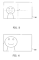
- the relative position obtaining module 130 first obtains display positions of the user's eyes in an input image 400. Then, after a shift reference point X set on the input image 400 and the eye positions are compared, the eye positions are found to be higher than the shift reference point X. Hence, it is determined that the user is currently viewing the display 110 from an angle higher than the display 110.
- the input image captured by the user detecting module 120 is an input image 500 as shown in FIG.
- the shift reference point X can be set in the central points of the input images 400 and 500, but the disposition of the shift reference point X actually is not limited to this.
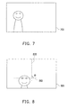
- FIGs. 6 and 7 are schematic views of an input image including a user according to another embodiment of the present disclosure.
- the relative position obtaining module 130 first determines the user's eye positions by the facial detecting technology, thereby obtaining the user's eye outlines. Thereafter, a size and proportion between the eye outlines and the input image 600 is calculated. Finally, the size and proportion and a preset proportion reference value are compared to determine a distance between the user and the display 110. For example, when the user is closer to the display 110, the size and proportion of the eyes in the input image becomes larger (as shown by the input image 600 in FIG. 6 ).
- a current distance between the user and the display 110 is determined by the size and proportion of the facial feature in the input image.
- the user may have to rotate the display 110 for viewing because the frame is displayed in a different direction.
- an input image 800 as shown in FIG. 8 is captured by the user detecting module 120.
- an angle ⁇ formed by a connected line 810 of the user's eye positions and a rotating reference line 820 set on the input image 800 is 90 degrees.
- an input image captured by the user detecting module 120 is an input image 900 as shown by FIG. 9 , for example.
- a connected line 910 of the user's eye positions is parallel to a rotating reference line 920 set on the input image 900.
- a rotating angle of the user relative to the display 110 can be determined by an angle formed by the connected line of the user's eye positions and the rotating reference line set on the input image.
- the rotating reference lines 820 and 920 are a horizontal line or a vertical line preset on the input images 800 and 900 respectively, but the disposition of the rotating reference lines in fact is not limited thereto.
- the relative position obtaining module 130 not only determines that the user is currently viewing the display 110 in a position slanting upwards or downwards, or slanting towards the left or the right according to the input image captured by the user detecting module 120. Meanwhile, the relative position obtaining module 130 also determines information as what the distance is between the user and the display 110 and whether or not the user rotates the display 110. However, it should be emphasized that the relative position obtaining module 130 can obtain the facial feature by any facial identification or detecting technology and calculate the relative position between the user and the display 110. In the present disclosure, the relative position is not limited to the shift, rotating angle and distance between the user and the display. Likewise, an algorithm for obtaining the relative position is not limited, either.
- the image processing module 140 adjusts the output frame of the display 110 correspondingly according to the relative position.
- the image processing module 140 timely scales the contents of the output frame according the distance between the user and the display 110. For example, when the distance between the user and the display 110 is farther, words or graphics in the output frame are automatically enlarged. When the user is very close to the display 110, the contents in the output frame such as words and graphics are displayed in a reduced size or a standard size.
- the image processing module 140 can, for example, shift the output frame correspondingly in a direction of the shift so as to achieve an effect similar to rolling frames. Or, after a current view angle and position of the user is calculated according to the shift, when the user is determined as being in a dead angle of gray scale inversion of an LCD, the image processing module 140 first adjusts colors of the output frame and then controls the display 110 to output the frames so that the user sees the frames in the correct colors.
- the image processing module 140 rotates the output frame correspondingly according to the rotating angle. For example, when the user rotates the display 110 by 90 degrees, the image processing module 140 changes a display direction of the output frame from the original vertical direction to a horizontal direction. It should be noted that besides rotating the output frame by 90 degrees, if the user detecting module 120 captures an input image 1000 as shown by FIG. 10 , the image processing module 140 also rotates the output frame correspondingly according to an angle 0 formed by a connected line 1010 of the user's eye positions and a rotating reference line 1020 set on the input image 1000 (i.e., the output frame being rotated by ⁇ degrees and then outputted by the display 110). Thus, the user can view the words or graphics in the output frame more conveniently.
- the image processing module 140 can further change the contents of the output frame according to the relative position between the user and the display 110. For example, when the user is close to the display 110, the image processing module 140 controls the display 110 to output a frame with an analog clock. When the user keeps a farther distance from the display 110, the output frame is changed into a digital clock to enhance readability. According to still another embodiment, the image processing module 140 can further display different output frames according to the angle at which the user rotates the display 110 so as to achieve an effect similar to displaying a laser animation sticker or flipping through pages.
- the image processing module 140 optimizes the output frame by adjusting pixels of the output frame, for example, to present the best 3D display result so that the view angle issue of the 3D display is resolved.
- the method and the device for adjusting the output frame in the present disclosure correspondingly adjusts the output frame according to the relative position between the user and the display.
- the output frame is displayed not only in the most suitable size, the most correct colors and the best angle, flexibility of the output frame is also enhanced simultaneously so that the user enjoys the optimal display result in any view position, and the impression formed from use of the electronic device improves as well.
Landscapes
- Engineering & Computer Science (AREA)
- Theoretical Computer Science (AREA)
- General Engineering & Computer Science (AREA)
- Physics & Mathematics (AREA)
- General Physics & Mathematics (AREA)
- Human Computer Interaction (AREA)
- Computer Vision & Pattern Recognition (AREA)
- Controls And Circuits For Display Device (AREA)
- User Interface Of Digital Computer (AREA)
Applications Claiming Priority (1)
| Application Number | Priority Date | Filing Date | Title |
|---|---|---|---|
| TW096151587A TW200928860A (en) | 2007-12-31 | 2007-12-31 | Method and device for adjusting output frame |
Publications (2)
| Publication Number | Publication Date |
|---|---|
| EP2075761A1 true EP2075761A1 (de) | 2009-07-01 |
| EP2075761B1 EP2075761B1 (de) | 2012-04-11 |
Family
ID=40510429
Family Applications (1)
| Application Number | Title | Priority Date | Filing Date |
|---|---|---|---|
| EP08022428A Ceased EP2075761B1 (de) | 2007-12-31 | 2008-12-23 | Verfahren und Gerät für die Anpassung des Ausgangsrahmens |
Country Status (3)
| Country | Link |
|---|---|
| US (1) | US8625844B2 (de) |
| EP (1) | EP2075761B1 (de) |
| TW (1) | TW200928860A (de) |
Cited By (4)
| Publication number | Priority date | Publication date | Assignee | Title |
|---|---|---|---|---|
| EP2189835A1 (de) * | 2008-11-19 | 2010-05-26 | Sony Ericsson Mobile Communications AB | Endgerätevorrichtung, Anzeigesteuerungsverfahren und Anzeigesteuerungsprogramm |
| EP2761422A4 (de) * | 2011-09-30 | 2015-05-06 | Intel Corp | Mechanismus zur ermöglichung einer erweiterten anzeigeperspektive von videobildern auf rechnervorrichtungen |
| CN107632710A (zh) * | 2013-03-15 | 2018-01-26 | 奇跃公司 | 显示系统和方法 |
| CN111459264A (zh) * | 2018-09-18 | 2020-07-28 | 阿里巴巴集团控股有限公司 | 3d对象交互系统和方法及非暂时性计算机可读介质 |
Families Citing this family (19)
| Publication number | Priority date | Publication date | Assignee | Title |
|---|---|---|---|---|
| CN101788876A (zh) * | 2009-01-23 | 2010-07-28 | 英华达(上海)电子有限公司 | 自动缩放调整的方法及其系统 |
| CN101877736A (zh) * | 2009-04-30 | 2010-11-03 | 深圳富泰宏精密工业有限公司 | 移动终端用户界面自动调整系统及方法 |
| CN102014236B (zh) * | 2009-09-08 | 2014-04-23 | 鸿富锦精密工业(深圳)有限公司 | 互动式影像播放系统及方法 |
| TW201112045A (en) * | 2009-09-28 | 2011-04-01 | Wistron Corp | Viewing direction determination method, viewing direction determination apparatus, image processing method, image processing apparatus and display device |
| TWI393430B (zh) * | 2009-10-29 | 2013-04-11 | Ind Tech Res Inst | 立體顯示器的像素資料轉換方法與裝置 |
| US8508581B2 (en) | 2009-10-29 | 2013-08-13 | Industrial Technology Research Institute | Pixel data transformation method and apparatus for three dimensional display |
| US8928659B2 (en) * | 2010-06-23 | 2015-01-06 | Microsoft Corporation | Telepresence systems with viewer perspective adjustment |
| TW201239869A (en) * | 2011-03-24 | 2012-10-01 | Hon Hai Prec Ind Co Ltd | System and method for adjusting font size on screen |
| TW201239644A (en) * | 2011-03-24 | 2012-10-01 | Hon Hai Prec Ind Co Ltd | System and method for dynamically adjusting font size on screen |
| CN103309433B (zh) * | 2012-03-06 | 2016-07-06 | 联想(北京)有限公司 | 一种自动调整电子设备摆放状态的方法、电子设备 |
| TWI482082B (zh) * | 2012-12-27 | 2015-04-21 | Qisda Corp | 電子裝置之畫面旋轉方法 |
| CN104423719A (zh) * | 2013-08-27 | 2015-03-18 | 鸿富锦精密工业(深圳)有限公司 | 电子装置及显示内容更新方法 |
| KR102509533B1 (ko) | 2014-02-25 | 2023-03-14 | 애플 인크. | 비디오 인코딩 및 디코딩을 위한 적응형 전달 함수 |
| US20150371120A1 (en) * | 2014-06-18 | 2015-12-24 | Sarfaraz K. Niazi | Visual axis optimization for enhanced readability and comprehension |
| CN105469773B (zh) * | 2014-09-03 | 2018-03-09 | 富泰华工业(深圳)有限公司 | 显示屏亮度调节方法及系统 |
| US9967529B2 (en) * | 2015-06-04 | 2018-05-08 | Disney Enterprises, Inc. | Output light monitoring for benchmarking and enhanced control of a display system |
| US10452135B2 (en) * | 2015-07-30 | 2019-10-22 | Dell Products L.P. | Display device viewing angel compensation system |
| CN112738404B (zh) * | 2020-12-30 | 2022-11-25 | 维沃移动通信(杭州)有限公司 | 电子设备的控制方法及电子设备 |
| US11783449B2 (en) * | 2021-12-09 | 2023-10-10 | Htc Corporation | Method for adjusting displayed content based on host posture, host, and computer readable storage medium |
Citations (5)
| Publication number | Priority date | Publication date | Assignee | Title |
|---|---|---|---|---|
| US5574836A (en) * | 1996-01-22 | 1996-11-12 | Broemmelsiek; Raymond M. | Interactive display apparatus and method with viewer position compensation |
| EP0845737A2 (de) * | 1996-11-29 | 1998-06-03 | Canon Kabushiki Kaisha | Bildanzeigeverfahren und -gerät |
| EP0874303A1 (de) * | 1997-04-25 | 1998-10-28 | Texas Instruments France | Videoanzeigesystem zum Darstellen einer virtuellen dreidimensionalen Bildanzeige |
| US6009210A (en) * | 1997-03-05 | 1999-12-28 | Digital Equipment Corporation | Hands-free interface to a virtual reality environment using head tracking |
| US6011581A (en) * | 1992-11-16 | 2000-01-04 | Reveo, Inc. | Intelligent method and system for producing and displaying stereoscopically-multiplexed images of three-dimensional objects for use in realistic stereoscopic viewing thereof in interactive virtual reality display environments |
Family Cites Families (10)
| Publication number | Priority date | Publication date | Assignee | Title |
|---|---|---|---|---|
| TW455769B (en) | 1999-08-18 | 2001-09-21 | Jian Huei Jiuan | Eye-protection method and apparatus set up for monitor screen |
| US6864912B1 (en) * | 1999-12-16 | 2005-03-08 | International Business Machines Corp. | Computer system providing hands free user input via optical means for navigation or zooming |
| US7203911B2 (en) * | 2002-05-13 | 2007-04-10 | Microsoft Corporation | Altering a display on a viewing device based upon a user proximity to the viewing device |
| US7883415B2 (en) * | 2003-09-15 | 2011-02-08 | Sony Computer Entertainment Inc. | Method and apparatus for adjusting a view of a scene being displayed according to tracked head motion |
| US7874917B2 (en) * | 2003-09-15 | 2011-01-25 | Sony Computer Entertainment Inc. | Methods and systems for enabling depth and direction detection when interfacing with a computer program |
| JP4770178B2 (ja) | 2005-01-17 | 2011-09-14 | ソニー株式会社 | カメラ制御装置、カメラシステム、電子会議システムおよびカメラ制御方法 |
| TWI287204B (en) | 2005-03-18 | 2007-09-21 | Mitac Int Corp | Automatic adjustment for the picture display direction for a handheld electronic device |
| JP4814232B2 (ja) | 2005-07-01 | 2011-11-16 | パナソニック株式会社 | 液晶表示装置 |
| TWI309034B (en) | 2005-12-30 | 2009-04-21 | High Tech Comp Corp | Display controller |
| TWI277848B (en) | 2006-01-11 | 2007-04-01 | Ind Tech Res Inst | Apparatus for automatically adjusting display parameters relying on visual performance and method for the same |
-
2007
- 2007-12-31 TW TW096151587A patent/TW200928860A/zh unknown
-
2008
- 2008-12-23 EP EP08022428A patent/EP2075761B1/de not_active Ceased
- 2008-12-25 US US12/344,271 patent/US8625844B2/en not_active Expired - Fee Related
Patent Citations (5)
| Publication number | Priority date | Publication date | Assignee | Title |
|---|---|---|---|---|
| US6011581A (en) * | 1992-11-16 | 2000-01-04 | Reveo, Inc. | Intelligent method and system for producing and displaying stereoscopically-multiplexed images of three-dimensional objects for use in realistic stereoscopic viewing thereof in interactive virtual reality display environments |
| US5574836A (en) * | 1996-01-22 | 1996-11-12 | Broemmelsiek; Raymond M. | Interactive display apparatus and method with viewer position compensation |
| EP0845737A2 (de) * | 1996-11-29 | 1998-06-03 | Canon Kabushiki Kaisha | Bildanzeigeverfahren und -gerät |
| US6009210A (en) * | 1997-03-05 | 1999-12-28 | Digital Equipment Corporation | Hands-free interface to a virtual reality environment using head tracking |
| EP0874303A1 (de) * | 1997-04-25 | 1998-10-28 | Texas Instruments France | Videoanzeigesystem zum Darstellen einer virtuellen dreidimensionalen Bildanzeige |
Cited By (8)
| Publication number | Priority date | Publication date | Assignee | Title |
|---|---|---|---|---|
| EP2189835A1 (de) * | 2008-11-19 | 2010-05-26 | Sony Ericsson Mobile Communications AB | Endgerätevorrichtung, Anzeigesteuerungsverfahren und Anzeigesteuerungsprogramm |
| US8350896B2 (en) | 2008-11-19 | 2013-01-08 | Sony Mobile Communications Japan, Inc. | Terminal apparatus, display control method, and display control program |
| EP2761422A4 (de) * | 2011-09-30 | 2015-05-06 | Intel Corp | Mechanismus zur ermöglichung einer erweiterten anzeigeperspektive von videobildern auf rechnervorrichtungen |
| US9060093B2 (en) | 2011-09-30 | 2015-06-16 | Intel Corporation | Mechanism for facilitating enhanced viewing perspective of video images at computing devices |
| CN107632710A (zh) * | 2013-03-15 | 2018-01-26 | 奇跃公司 | 显示系统和方法 |
| CN107632710B (zh) * | 2013-03-15 | 2021-04-30 | 奇跃公司 | 显示系统和方法 |
| CN111459264A (zh) * | 2018-09-18 | 2020-07-28 | 阿里巴巴集团控股有限公司 | 3d对象交互系统和方法及非暂时性计算机可读介质 |
| CN111459264B (zh) * | 2018-09-18 | 2023-04-11 | 阿里巴巴集团控股有限公司 | 3d对象交互系统和方法及非暂时性计算机可读介质 |
Also Published As
| Publication number | Publication date |
|---|---|
| TW200928860A (en) | 2009-07-01 |
| EP2075761B1 (de) | 2012-04-11 |
| US20090169058A1 (en) | 2009-07-02 |
| US8625844B2 (en) | 2014-01-07 |
Similar Documents
| Publication | Publication Date | Title |
|---|---|---|
| US8625844B2 (en) | Method and device for adjusting output frame | |
| CN101499253B (zh) | 输出画面的调整方法与装置 | |
| TWI413979B (zh) | 調整顯示畫面的方法、電子裝置,與電腦程式產品 | |
| US20110096095A1 (en) | Display device and method for adjusting image on display screen of the same | |
| KR102254540B1 (ko) | 곡면형 표시 장치 및 이의 구동방법 | |
| US11275248B2 (en) | Head mounted display apparatus, virtual reality display system and driving method thereof | |
| EP2312861A2 (de) | Stereoskopische Anzeigevorrichtung und Bildverarbeitungsverfahren dafür | |
| US20200402481A1 (en) | Image display method, image processing method and relevant devices | |
| CN109741289B (zh) | 一种图像融合方法和vr设备 | |
| WO2022048424A1 (zh) | 屏幕画面自适应调整方法、装置、设备和存储介质 | |
| EP2755164A2 (de) | Anzeigevorrichtung und Steuerungsverfahren zur Anpassung der Augen eines fotografierten Benutzers | |
| CN104298482B (zh) | 移动终端自动调整输出的方法 | |
| US20190027118A1 (en) | Terminal device and display method | |
| CN104252828A (zh) | 保护视力的显示方法、显示装置和终端设备 | |
| CN107707901B (zh) | 一种用于裸眼3d显示屏幕的显示方法、装置及设备 | |
| JP2004320661A (ja) | 補助線を利用した幾何学補正インターフェースにおける画面外エリアの補正方法 | |
| US9536133B2 (en) | Display apparatus and control method for adjusting the eyes of a photographed user | |
| WO2019000534A1 (zh) | 终端设备及显示方法 | |
| CN120111208A (zh) | 利用双目差别机制提升vr设备细节显示质量的方法 | |
| CN110211543B (zh) | 局部背光调节方法和装置、虚拟现实系统 | |
| CN107608504A (zh) | 移动终端和智能文字显示方法 | |
| CN113805655B (zh) | 显示方法、装置和电子设备 | |
| KR101686099B1 (ko) | 영상 표시장치의 구동장치와 그 구동방법 | |
| KR101782008B1 (ko) | 영상 크기 조정 장치 및 그 방법과, 영상 크기 조정 장치를 포함하는 액정표시장치 및 그 구동방법 | |
| CN117524073B (zh) | 一种超高清图像显示抖动补偿方法、系统及存储介质 |
Legal Events
| Date | Code | Title | Description |
|---|---|---|---|
| PUAI | Public reference made under article 153(3) epc to a published international application that has entered the european phase |
Free format text: ORIGINAL CODE: 0009012 |
|
| 17P | Request for examination filed |
Effective date: 20081223 |
|
| AK | Designated contracting states |
Kind code of ref document: A1 Designated state(s): AT BE BG CH CY CZ DE DK EE ES FI FR GB GR HR HU IE IS IT LI LT LU LV MC MT NL NO PL PT RO SE SI SK TR |
|
| AX | Request for extension of the european patent |
Extension state: AL BA MK RS |
|
| 17Q | First examination report despatched |
Effective date: 20100112 |
|
| AKX | Designation fees paid |
Designated state(s): DE FR GB |
|
| GRAP | Despatch of communication of intention to grant a patent |
Free format text: ORIGINAL CODE: EPIDOSNIGR1 |
|
| GRAS | Grant fee paid |
Free format text: ORIGINAL CODE: EPIDOSNIGR3 |
|
| GRAA | (expected) grant |
Free format text: ORIGINAL CODE: 0009210 |
|
| AK | Designated contracting states |
Kind code of ref document: B1 Designated state(s): DE FR GB |
|
| REG | Reference to a national code |
Ref country code: GB Ref legal event code: FG4D |
|
| REG | Reference to a national code |
Ref country code: DE Ref legal event code: R096 Ref document number: 602008014727 Country of ref document: DE Effective date: 20120606 |
|
| PLBE | No opposition filed within time limit |
Free format text: ORIGINAL CODE: 0009261 |
|
| STAA | Information on the status of an ep patent application or granted ep patent |
Free format text: STATUS: NO OPPOSITION FILED WITHIN TIME LIMIT |
|
| 26N | No opposition filed |
Effective date: 20130114 |
|
| REG | Reference to a national code |
Ref country code: DE Ref legal event code: R097 Ref document number: 602008014727 Country of ref document: DE Effective date: 20130114 |
|
| REG | Reference to a national code |
Ref country code: FR Ref legal event code: PLFP Year of fee payment: 8 |
|
| REG | Reference to a national code |
Ref country code: FR Ref legal event code: PLFP Year of fee payment: 9 |
|
| REG | Reference to a national code |
Ref country code: FR Ref legal event code: PLFP Year of fee payment: 10 |
|
| PGFP | Annual fee paid to national office [announced via postgrant information from national office to epo] |
Ref country code: DE Payment date: 20181211 Year of fee payment: 11 |
|
| PGFP | Annual fee paid to national office [announced via postgrant information from national office to epo] |
Ref country code: GB Payment date: 20181219 Year of fee payment: 11 Ref country code: FR Payment date: 20181120 Year of fee payment: 11 |
|
| REG | Reference to a national code |
Ref country code: DE Ref legal event code: R119 Ref document number: 602008014727 Country of ref document: DE |
|
| GBPC | Gb: european patent ceased through non-payment of renewal fee |
Effective date: 20191223 |
|
| PG25 | Lapsed in a contracting state [announced via postgrant information from national office to epo] |
Ref country code: DE Free format text: LAPSE BECAUSE OF NON-PAYMENT OF DUE FEES Effective date: 20200701 Ref country code: GB Free format text: LAPSE BECAUSE OF NON-PAYMENT OF DUE FEES Effective date: 20191223 Ref country code: FR Free format text: LAPSE BECAUSE OF NON-PAYMENT OF DUE FEES Effective date: 20191231 |