EP0845773A2 - Mehrton-Schlaginstrumente - Google Patents
Mehrton-Schlaginstrumente Download PDFInfo
- Publication number
- EP0845773A2 EP0845773A2 EP97402638A EP97402638A EP0845773A2 EP 0845773 A2 EP0845773 A2 EP 0845773A2 EP 97402638 A EP97402638 A EP 97402638A EP 97402638 A EP97402638 A EP 97402638A EP 0845773 A2 EP0845773 A2 EP 0845773A2
- Authority
- EP
- European Patent Office
- Prior art keywords
- bars
- support structure
- percussion instrument
- dampening element
- pedal
- Prior art date
- Legal status (The legal status is an assumption and is not a legal conclusion. Google has not performed a legal analysis and makes no representation as to the accuracy of the status listed.)
- Granted
Links
Images


Classifications
-
- G—PHYSICS
- G10—MUSICAL INSTRUMENTS; ACOUSTICS
- G10D—STRINGED MUSICAL INSTRUMENTS; WIND MUSICAL INSTRUMENTS; ACCORDIONS OR CONCERTINAS; PERCUSSION MUSICAL INSTRUMENTS; AEOLIAN HARPS; SINGING-FLAME MUSICAL INSTRUMENTS; MUSICAL INSTRUMENTS NOT OTHERWISE PROVIDED FOR
- G10D13/00—Percussion musical instruments; Details or accessories therefor
- G10D13/01—General design of percussion musical instruments
- G10D13/08—Multi-toned musical instruments with sonorous bars, blocks, forks, gongs, plates, rods or teeth
Definitions
- the present invention relates to mallet percussion instruments such as vibes, xylophones and marimbas, and particularly relates to such instruments having various novel and improved constructional features facilitating the construction and portability of the instrument, improving its sound quality, rendering the instrument easier to play and eliminating sounds characteristic of conventional instrument constructions and deleterious to their musical qualities.
- the present invention provides a novel and unique shock-absorbing bar mounting system which enables the bars to be suspended without transmittal of substantial vibration to the instrument supporting structure or to adjacent bars, hence minimizing or substantially eliminating non-musical sounds.
- the present invention provides mount bars having resilient elements on which the flexible line supporting the bars may rest. With the bars isolated from the support structure by the resilient elements, the vibration of the bars transmitted along the bar support line to the resilient elements is substantially absorbed.
- Two types of mount bars are provided: first, a generally Y-shaped mount bar with a resilient element extending between the two upwardly-directed projections for receiving the line therebetween and, secondly, a similar bar mount with the distal end of one of the projections forming an overlying hook maintaining the line in engagement with the resilient element.
- the ends of the rows remote from one another are supported by a line extending over the resilient elements of the first bar mounts.
- the ends of the bars of the rows adjacent one another are supported by the line in the bar mounts having the hooks for restraining the bars when damped.
- a dampening rail supported by the support structure for movement between a position engaged along the underside of the adjacent ends of the bars in adjacent rows and a position spaced below those bars. Consequently, when the dampening rail engages the bars, the hooks of the bar mounts prevent the line and hence the bars from elevating above the bar mounts. Additionally, the dampening rail extends the entire length of the instrument, underlying all of the bars of the two rows at adjacent innermost ends of the bars.
- the dampening rail comprises a sealed bladder filled with fluid, such as water.
- the dampening rail is carried on the distal end of a pair of arms pivotally secured to one side of the support structure.
- the support structure also carries a pair of spring bridges adjustably supported from the support structure to adjustably space the dampening rail from the underside of the bars. These bridge pieces can be independently adjusted and each carries a compression spring engaging the underside of the dampening rail whereby the pressure along the rail can be increased or decreased and evenly distributed to the bars.
- a further feature of the present invention resides in a pedal arrangement which not only can be moved from side to side to accommodate the player of the instrument but also can be adjusted to change the feel of the pedal.
- the pedal is supported by the support frame and is locked in adjusted lateral positions along the support frame.
- the pedal connects with the dampening rail through an interconnecting pivotal linkage which, like the pedal per se , is laterally adjustable along the dampening rail.
- the interconnecting pivotal linkage can be locked in adjusted position to adjust the feel of the pedal.
- the linkage can be adjusted so that the stroke or throw of the pedal is reduced, affording a fairly stiff dampening reaction to the bars.
- the throw of the pedal can be increased to provide a softer engagement between the dampening rail and the bars.
- the resonators underlying the bars are adjustable in height relative to the bars.
- the resonators are carried by a supporting sub-structure which, at its ends, is carried by the support structure. Interposed between the sub-structure and the support structure are adjusting elements such that the sub-structure, and hence the resonators, can be raised or lowered relative to the bars.
- Additional features of the present invention will become apparent from a review of the ensuing detailed description.
- Such additional features include the portability of the instrument afforded by its fabrication from aluminum bar stock, using telescoping support sections to enable the height of the instrument to be adjusted.
- the bar stock includes slotted side walls enabling use of quick connect/disconnect mechanisms for adjusting the elements relative to one another, for example, displacing the pedal assembly laterally along the support structure into an adjusted position.
- Wheels are provided adjacent one end of the instrument such that, upon folding the legs into positions underlying the playing table, the instrument may be transported in a similar manner to a dolly.
- a percussion instrument having a plurality of discrete elongated bars spaced one from the other and coupled to one another by a flexible line suspending the bars at each of the opposite ends of the bars from a support structure, comprising a plurality of bar mounts arranged on the support structure at locations for engagement by the flexible line between the bars and resilient elements carried by the bar mounts and forming supports for the flexible line and the bars carried thereby whereby the resilient elements substantially vibrationally isolate the bars from one another and the bars and support structure from one another upon striking and vibrating the bars.
- a percussion instrument comprising a support structure, a flexible line, a plurality of discrete elongated bars spaced from one another and supported by the flexible line adjacent the opposite ends of the bars, a plurality of bar mounts arranged on the support structure at locations for engagement by the flexible line between the bars and resilient elements carried by the bar mounts and forming supports for the flexible line and bars carried thereby whereby the resilient elements substantially vibrationally isolate the bars and the support structure from one another upon striking and vibrating the bars.
- a percussion instrument comprising a support structure, a plurality of discrete elongated bars spaced from one another and support by the support structure, a plurality of resonator tubes spaced below the bars, a resonator tube sub-structure for supporting the resonator tubes below the bars, the sub-structure being carried by the support structure, an adjusting element between the support structure and the sub-structure for adjusting the spacing of the resonator tubes relative to the bars.
- a percussion instrument comprising a support structure, a plurality of discrete generally parallel elongated bars spaced from one another and supported by the support structure, the bars being arranged in two longitudinally extending rows thereof with the bars lying generally perpendicular to the longitudinal extent of the rows and an elongated dampening element extending generally parallel to and between the rows, the dampening element being carried by the support structure for movement between positions in and out of engagement with the bars of each row.
- a percussion instrument constructed in accordance with the present invention.
- the percussion instrument may be any one of several different types, for example, a vibraphone, a marimba or a xylophone.
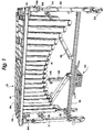
- the general arrangement of the instrument 10 includes a support frame 12 supporting a plurality of bars 14 arranged in two generally longitudinal parallel rows 14a and 14b with underlying resonators 15.
- the bars are supported on structure 12 by endless lines 16a and 16b for respective rows 14a and 14b of bars 14.
- the lines 16 are mounted on bar mounts 18 secured to the support structure 12 as described below.
- Support structure 12 is generally formed of a plurality of lightweight, preferably aluminum tubular bars.
- a pair of vertical uprights 20 are provided at each of the opposite ends of the support structure 12, the ends being wider and narrower, respectively, as is conventional in instruments of this type, and hereafter referred to as the large and small ends, respectively.
- the uprights 20 are formed of telescoping sections such that the height of the instrument bed 22 supported by the end pairs of uprights 20 can be adjusted. Conventional quick locking and unlocking mechanisms are provided to adjust the extent of the telescoping sections, the sections being locked and unlocked in adjusted positions by rotation of handles 24 in a known manner.
- the lower ends of the end uprights 20 are provided with casters 26 so that the instrument can be moved about a floor, the casters preferably being provided with locking elements so that the position of the instrument can be fixed.
- the casters also are individually adjusted in height, e.g., to accommodate uneven floors.
- the pairs of end uprights 20 have cross members 28 and 30 ( Figure 1) to stabilize the support for the instrument bed 22. Also connected between the lowermost cross supports 30 is an elongated reinforcing support 32 which mounts a pedal assembly 34 for the instrument.
- the opposite ends of the longitudinally extending support 32 are releasably secured to the cross supports 30 at various positions therealong whereby the pedal assembly 34 can be adjustably positioned relative to the front and back sides of the instrument, i.e., adjusted forwardly and rearwardly as necessary and desirous.
- Diagonally extending telescopic support members 36 are pivotally connected at one end to the long support 32 and at their opposite ends to the upper cross support 28 of the end pair of uprights 20.
- the end uprights 20 are pivotally coupled to a pair of front and back longitudinally extending supports 38 forming part of the support bed 22 for the instrument 10.
- the supports 38 are interconnected at opposite ends by cross supports 40 forming the substantially rigid bed 22 of the instrument.
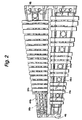
- Bed 22 also includes a pair of bar mounting rails 44a for the front row of bars 14a and a pair of rails 44b for the rear bars 14b.
- the bar support rails 44a diverge from one another from the small end to the large end of the instrument, while the rails 44b similarly diverge one from the other from the small to the large end of the instrument.
- the bar support rails 44 are each mounted in cross rail holders or plates 46 and 48 at the opposite small and large ends, respectively, of the instrument 10.
- the bar rail holders 46 and 48 as illustrated in Figure 6, are grooved for receiving the lower sides of bar support rails 44a and 44b, the holders 46 and 48 being directly connected to and supported by the longitudinal and cross supports 38 and 40, respectively, of the support structure 12.
- each of the bar mounting rails 44 has a plurality of longitudinally spaced openings through its top side for receiving the lower or shank ends of bar mounts 50 and 52.
- Bar mounts 50 and 52 are for purposes of supporting the line 16 which, in turn, supports the individual bars 14. It will be appreciated that the line 16 may comprise an endless loop for each row of bars and is preferably formed of a textile material.
- the bar mounts 50 and 52 are specifically designed to dampen the transmission of vibration from the bars to the support structure or to adjacent bars when the bars are struck by a mallet.
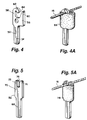
- bar mounts 50 and 52 are of two different types: a first type being utilized along the interior or adjacent bar support rails 44a and 44b, while the second type 52 is used along the exterior bar support rails 44a and 44b.
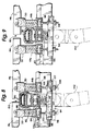
- the interior bar mounts 50 each include a depending shank 54, generally rectilinear in configuration, and a head 56 formed, in part, by a pair of upwardly projecting, laterally spaced fingers 58 and 60.
- the upper end of finger 58 is reversely curved to form a hook 62 which extends substantially halfway across the gap between fingers 58 and 60 and forms an opening 64 with the opposed finger 60 to the area between fingers 58 and 60 below hook 62.
- a sleeve 66 formed of a resilient material such as latex rubber is received about the head 56 and overlies a portion of the gap between fingers 58 and 60. With the line 16 received in each opening 64 and within the concave portion of hook 62, sleeve 66 is disposed about the head 56 such that the line 16 rests on the upper margin of sleeve 66.
- the bar mount 52 for the outside bar mount rails 44a and 44b includes a shank 68 similar to shank 54, a head 70 and a pair of upwardly projecting, laterally spaced fingers 72 and 74 forming a slot 76 therebetween for receiving a line 16.
- the head 70 includes a resilient sleeve 78.
- the upper margins of the resilient sleeve 78 support line 16.
- the support of line 16 by both resilient sleeves 68 and 78 isolates the vibration transmitted from a bar struck by a mallet along the line 16 from adjacent bars and from the support structure 12.
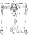
- a dampening rail movable between positions engaging and disengaged from the underside of the inner ends of bars 14a and 14b, the dampening rail 80 lying between the inner bar support rails 44a and 44b.
- the dampening assembly includes a pair of elongated structural tubes 82 and 84 superposed one over the other and secured to one another, for example, by bolts.
- the tubes 82 and 84 are positioned along a central longitudinal portion of the instrument by a pair of transversely extending supports 86 pivoted at one end to the cross supports 40 and secured at their opposite ends to the lower tube 84, enabling the tubes 82 and 84 to move between the positions illustrated in Figures 8 and 9.
- a bladder 88 preferably filled with a liquid such as water and which bladder 88 extends the length of the instrument, including between opposed ends (interior ends) of the bars of the row thereof.
- the bladder is a sealed container such that pressures exerted on the bladder at any location therealong are immediately transmitted throughout the length of the bladder whereby the pressure along the bladder is equalized.
- a pad 90 of cloth or felt material Overlying the bladder 88 is a pad 90 of cloth or felt material and which pad 90 engages the underside of the bars 14 of the rows of bars 14a and 14b.
- the lower tube 84 of the dampening assembly 80 has an elongated slot 92 formed along its underside for facilitating releasable securement of the pedal assembly 34 to the dampening rail 80.
- a pair of spring bridges 94 are provided along the underside of the bed 22 for supporting and biasing the dampening rail 80 into the position engaged along the underside of the bars, as illustrated in Figure 8.
- Each of the spring bridges 94 includes a short cross piece 96 of tubular construction dependently and adjustably secured below a pair of elongated longitudinally extending beams 98 secured along the undersides of the inner bar support rails 44a and 44b. The bridges 98 thus straddle the dampening rail 80.
- Each of the beams 98 is of rectilinear cross section having a slot 100 formed along its underside.
- Elongated bolts 102 having heads 104 lying within the beams 98 dependently support the spring bridges 96 in adjusted elevational position relative to tube 84.
- the cross bridges 96 may span between opposite sides of the dampening rail 80 below the tube 84 at adjustable elevational and longitudinal positions relative to the beams 98.
- Each of the bridges 96 carries a coil spring 110 which engages between the bridge 96 and the underside of tube 84, biasing the tubes and the bladder in a vertically upward direction to engage the pad 90 against the underside of the bars 14.
- the support arms 86 position the dampening rail 80 transversely of the instrument 10, while the bridges 96 and springs 110 carried thereby bias the dampening rail 80 for movement upwardly into engagement with the bars.
- the bridges can be located at longitudinally spaced positions along the instrument, as best illustrated in Figure 3.
- the pedal assembly 34 for displacing the dampening rail 80 into and out of engagement with the inner ends of the bars is best illustrated in Figure 6.
- the pedal assembly 34 is longitudinally displaceable along the support bar 32 into a longitudinally adjusted position.
- Quick lock and unlocking mechanisms may be used to lock and unlock the pedal assembly 34 in a longitudinally adjusted position.
- the pedal assembly 34 includes the pedal plate 120 which mounts adjacent its rear edge at longitudinally spaced positions a pair of lugs 122. These upstanding lugs 122 are pivotally secured to a pair of lugs 124 dependent from a plate 126 slidable along the support 32.
- the support 32 has a longitudinal groove or T-slot along its underside for receiving mating projections, also not shown, on plate 126 which can be loosened to permit longitudinal sliding of the pedal assembly along the length of the instrument and tightened to lock the pedal assembly in adjusted longitudinal positions along support 32.
- a lug 134 Centrally of the foot pedal 120 and slightly forwardly of the lugs 122 is a lug 134 to which is pivotally coupled a rod 136 surrounded by a square tube 138.
- the rod 136 and tube 138 are telescopic, enabling the pedal assembly to operate at different adjusted heights of the instrument.
- the upper end of the rod 136 is coupled to a fulcrum assembly, generally designated 140.
- the fulcrum assembly includes a lower hinge 142 coupled to rod 136, an intermediate link 144 and an upper fulcrum 146 pivotally connected to link 144. Fulcrum 146 is secured to a depending bracket 148, in turn secured to the underside of lower tube 84.
- the pivotal connections between the link 144 and fulcrums 142 and 146 can be locked and unlocked in adjusted positions, for example, as illustrated by the full and dashed lines in Figure 6. It will be appreciated that by depressing pedal 120, the dampening assembly, including the bladder 88 and dampening pad 90 are lowered, i.e., disengaged from the underside of the bars 14a and 14b.
- the springs 110 urge the dampening bladder 88 and pad 90 into engagement with the undersides of the bars 14a and 14b.
- the "feel" of the pedal may be altered. More particularly, the throw or displacement of the pedal 120 is greater and the feel is stiffer.
- the pedal has quick response in displacing the dampening assembly from the bars.
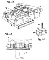
- the resonators 15 are mounted at elevationally adjusted positions relative to the bars 14.
- the resonators are suspended by a support sub-structure including a pair of longitudinally extending laterally spaced resonator support rails 170.
- the ends of rails 170 are, in turn, disposed in slots in resonator mounting beds 172 at the opposite ends of the instrument, respectively.
- Each mounting bed 172 is secured to the underside of an elevationally adjustable support plate 174, for example, by screws 176.
- the support plate 174 is carried on bolts 178 ( Figure 11).
- the height of the support plate 174 above the holder 46 and hence the height of the bed 172 at the opposite ends of the instrument may be adjusted by adjusting, tightening down or loosening the nuts 180 against the bias of springs 182 disposed between support plate 174 and holder 46.
- the ends of the resonator support rails 170 are carried by an adjustment block 186.
- the rails 170 seat on flanges 188 formed along the lower side of block 186.
- the block includes a set screw 190 threaded through block 186 for engagement with the surface of holder 46. It will be appreciated that by threading or unthreading the set screw 190, the block 186 may be raised or lowered relative to the holder 46 to adjust the height of the resonators 15 relative to the underside of the bars 14.
- the instrument 10 hereof can be readily and easily folded into a transportable position.
- the bars 14 are simply lifted from their bar mounts to remove the bars from the bed 22.
- the lines 16 underlying the hook 62 of the bar mounts 54 must first, of course, be displaced into the gap 64 to enable the bars to be lifted from the mounts.
- the longitudinal support rail 32 is then disconnected from the lower cross supports 30 and the diagonal supports 36 are disconnected from the upper cross supports 28.
- the upper ends of the telescoping portions of the vertical uprights 20 are pivotally secured along the underside of the bed 22. Consequently, the small end can be pivoted, for example, about the pivot axis 194 into substantial parallel relation with the bed 22.
- the large end uprights 20 can be pivoted about axes 196 into underlying relation to bed 22 and the opposite pair of support legs.
- a pair of dolly wheels 198 are pivotally secured to the bed 22 such that the folded instrument can be inclined with the wheels 198 engaging the ground. It will be appreciated that the resonators 15 and the supporting sub-structure may likewise be removed prior to folding the instrument for transport.
- inventions include the substantially all-aluminum construction whereby the instrument is substantially light in weight.
- the relatively moving parts are encapsulated, preferably in a material such as Teflon or some other high-density plastic to ensure smooth noiseless operation. In this manner, various non-musical sounds which would otherwise be attendant to the playing of the instrument are eliminated.
Landscapes
- Physics & Mathematics (AREA)
- Engineering & Computer Science (AREA)
- Acoustics & Sound (AREA)
- Multimedia (AREA)
- Auxiliary Devices For Music (AREA)
- Diaphragms For Electromechanical Transducers (AREA)
- Electromechanical Clocks (AREA)
- Surgical Instruments (AREA)
- Medicines Containing Antibodies Or Antigens For Use As Internal Diagnostic Agents (AREA)
- Arrangement Or Mounting Of Control Devices For Change-Speed Gearing (AREA)
Applications Claiming Priority (2)
| Application Number | Priority Date | Filing Date | Title |
|---|---|---|---|
| US08/757,764 US5977465A (en) | 1996-11-27 | 1996-11-27 | Mallet percussion instruments |
| US757764 | 1996-11-27 |
Publications (3)
| Publication Number | Publication Date |
|---|---|
| EP0845773A2 true EP0845773A2 (de) | 1998-06-03 |
| EP0845773A3 EP0845773A3 (de) | 1999-07-14 |
| EP0845773B1 EP0845773B1 (de) | 2003-05-14 |
Family
ID=25049126
Family Applications (1)
| Application Number | Title | Priority Date | Filing Date |
|---|---|---|---|
| EP97402638A Expired - Lifetime EP0845773B1 (de) | 1996-11-27 | 1997-11-05 | Mehrton-Schlaginstrumente |
Country Status (9)
| Country | Link |
|---|---|
| US (1) | US5977465A (de) |
| EP (1) | EP0845773B1 (de) |
| JP (1) | JPH10161647A (de) |
| KR (1) | KR19980042791A (de) |
| CN (1) | CN1185615A (de) |
| AT (1) | ATE240575T1 (de) |
| AU (1) | AU736980B2 (de) |
| DE (1) | DE69721945D1 (de) |
| TW (1) | TW355232B (de) |
Cited By (1)
| Publication number | Priority date | Publication date | Assignee | Title |
|---|---|---|---|---|
| GB2564440A (en) * | 2017-07-10 | 2019-01-16 | K H S Musical Instr Co Ltd | Support post for a suspended tone bar |
Families Citing this family (14)
| Publication number | Priority date | Publication date | Assignee | Title |
|---|---|---|---|---|
| US7732691B2 (en) * | 2007-06-25 | 2010-06-08 | Leigh H. Stevens | Methods and apparatus for vibrato effects in keyboard percussion musical instruments |
| USD590010S1 (en) * | 2008-01-24 | 2009-04-07 | Yamaha Corporation | Marimba |
| US8049089B2 (en) * | 2008-11-04 | 2011-11-01 | Leigh Howard Stevens | Keyboard percussion instrument and dampening system for use therewith |
| US20100192749A1 (en) * | 2009-02-02 | 2010-08-05 | Conn-Selmer, Inc. | Vibraphone |
| US8525009B2 (en) * | 2009-06-24 | 2013-09-03 | Leigh Howard Stevens | Multi-function musical instrument pedal controller |
| TWI396182B (zh) * | 2010-03-09 | 2013-05-11 | Oriental Inst Technology | Against sound toys |
| US9155296B2 (en) * | 2010-08-20 | 2015-10-13 | Evergreen Hunting Llc | Striker for calling game and method |
| CA2762576A1 (en) * | 2011-12-20 | 2013-06-20 | Mine Cristal Inc. | Percussion instrument |
| JP6583078B2 (ja) * | 2016-03-22 | 2019-10-02 | ヤマハ株式会社 | 楽器 |
| CN107785002A (zh) * | 2016-08-31 | 2018-03-09 | 天津市津宝乐器有限公司 | 马林巴共鸣管定位支撑装置 |
| US10593309B2 (en) * | 2017-01-18 | 2020-03-17 | Marimba One Inc. | Damper bar adjustment mechanism for keyboard percussion instrument |
| JP6579130B2 (ja) * | 2017-02-24 | 2019-09-25 | ヤマハ株式会社 | 楽器用スタンド |
| CN110070844B (zh) * | 2018-01-24 | 2024-09-10 | 鼓工场有限公司 | 直接驱动打击乐器踏板系统 |
| CN115909997A (zh) * | 2022-03-05 | 2023-04-04 | 奥列格·瓦西里耶维奇·日林 | 打击乐器发声元件的支撑结构和使用它的乐器 |
Family Cites Families (11)
| Publication number | Priority date | Publication date | Assignee | Title |
|---|---|---|---|---|
| US1902614A (en) * | 1933-03-21 | Control mechanism for vibra harps | ||
| US1293722A (en) * | 1917-10-24 | 1919-02-11 | Jefferson Claude Deagan | Xylophone. |
| US1843553A (en) * | 1930-08-25 | 1932-02-02 | William D Gladstone | Percussion musical instrument |
| US2133712A (en) * | 1937-09-20 | 1938-10-18 | Musser Clair Omar | Musical instrument |
| US2194545A (en) * | 1938-01-06 | 1940-03-26 | Conn Ltd C G | Musical instrument |
| DE1231530B (de) * | 1960-09-06 | 1966-12-29 | Margarethe Becker Ehmck | Stabspiel in Tischform |
| US3138986A (en) * | 1961-10-02 | 1964-06-30 | Scientific Industries | Vibraphone |
| US4848207A (en) * | 1986-10-13 | 1989-07-18 | Yamaha Corporation | Level adjuster for a musical instrument |
| DE19501472A1 (de) * | 1995-01-19 | 1996-07-25 | Leberecht Fischer Kg | Musikinstrument |
| JP3552319B2 (ja) * | 1995-01-20 | 2004-08-11 | ヤマハ株式会社 | 音板打楽器用音板 |
| DE19507468A1 (de) * | 1995-03-03 | 1996-09-05 | Leberecht Fischer Kg | Musikinstrument |
-
1996
- 1996-11-27 US US08/757,764 patent/US5977465A/en not_active Expired - Lifetime
-
1997
- 1997-09-23 AU AU39181/97A patent/AU736980B2/en not_active Ceased
- 1997-10-17 TW TW086115327A patent/TW355232B/zh active
- 1997-11-05 DE DE69721945T patent/DE69721945D1/de not_active Expired - Lifetime
- 1997-11-05 EP EP97402638A patent/EP0845773B1/de not_active Expired - Lifetime
- 1997-11-05 AT AT97402638T patent/ATE240575T1/de not_active IP Right Cessation
- 1997-11-25 JP JP9323168A patent/JPH10161647A/ja active Pending
- 1997-11-26 KR KR1019970063171A patent/KR19980042791A/ko not_active Ceased
- 1997-11-27 CN CN97122183A patent/CN1185615A/zh active Pending
Cited By (1)
| Publication number | Priority date | Publication date | Assignee | Title |
|---|---|---|---|---|
| GB2564440A (en) * | 2017-07-10 | 2019-01-16 | K H S Musical Instr Co Ltd | Support post for a suspended tone bar |
Also Published As
| Publication number | Publication date |
|---|---|
| KR19980042791A (ko) | 1998-08-17 |
| US5977465A (en) | 1999-11-02 |
| DE69721945D1 (de) | 2003-06-18 |
| TW355232B (en) | 1999-04-01 |
| AU736980B2 (en) | 2001-08-09 |
| ATE240575T1 (de) | 2003-05-15 |
| HK1011234A1 (en) | 1999-07-09 |
| EP0845773A3 (de) | 1999-07-14 |
| JPH10161647A (ja) | 1998-06-19 |
| EP0845773B1 (de) | 2003-05-14 |
| CN1185615A (zh) | 1998-06-24 |
| AU3918197A (en) | 1998-06-04 |
Similar Documents
| Publication | Publication Date | Title |
|---|---|---|
| US5977465A (en) | Mallet percussion instruments | |
| US4618144A (en) | Portable exercise device | |
| US7394008B2 (en) | Carrier assembly for percussion instruments | |
| US6537162B1 (en) | Direct mount telescopic adjustable backboard | |
| US10152955B2 (en) | Percussion pedal assembly | |
| US8053655B2 (en) | Carrier assembly for percussion instruments | |
| US6696628B2 (en) | Musical instrument stand | |
| US9406287B2 (en) | Portable component marimba | |
| US10943572B2 (en) | Instrument carrier with articulating back brace | |
| US10176789B2 (en) | Free floating integrated lug bridge | |
| US20050040193A1 (en) | Carrier assembly for percussion instruments | |
| US20070013154A1 (en) | Adjustable creeper apparatus | |
| US4589152A (en) | Fold-away bed assembly | |
| NL1002590C2 (nl) | Draaginrichting voor een muziekinstrument. | |
| US8049089B2 (en) | Keyboard percussion instrument and dampening system for use therewith | |
| HK1011234B (en) | Multi-tones percussion instruments | |
| CA2189259A1 (en) | Non-rotating stringing machine and method | |
| US5092213A (en) | Guitar saddle having an inclined lever portion | |
| WO1992010829A1 (en) | Stringed musical instrument | |
| US4881442A (en) | Playing height adjustment for keyboard percussion instruments | |
| US6245978B1 (en) | Keyboard musical percussion instrument tone bar suspension | |
| US5717152A (en) | Control device of a hi-hat cymbal | |
| US4342249A (en) | String mounting pitch changing apparatus for a pedal steel guitar | |
| US20060180003A1 (en) | Percussion instrument with improved damping mechanism | |
| NL1027490C2 (nl) | Slaginstrument met verbeterd dempmechanisme. |
Legal Events
| Date | Code | Title | Description |
|---|---|---|---|
| PUAI | Public reference made under article 153(3) epc to a published international application that has entered the european phase |
Free format text: ORIGINAL CODE: 0009012 |
|
| AK | Designated contracting states |
Kind code of ref document: A2 Designated state(s): AT BE CH DE DK ES FI FR GB GR IE IT LI NL PT SE |
|
| PUAL | Search report despatched |
Free format text: ORIGINAL CODE: 0009013 |
|
| AK | Designated contracting states |
Kind code of ref document: A3 Designated state(s): AT BE CH DE DK ES FI FR GB GR IE IT LI LU MC NL PT SE |
|
| 17P | Request for examination filed |
Effective date: 19991122 |
|
| AKX | Designation fees paid |
Free format text: AT BE CH DE DK ES FI FR GB GR IE IT LI NL PT SE |
|
| 17Q | First examination report despatched |
Effective date: 20010920 |
|
| GRAG | Despatch of communication of intention to grant |
Free format text: ORIGINAL CODE: EPIDOS AGRA |
|
| GRAG | Despatch of communication of intention to grant |
Free format text: ORIGINAL CODE: EPIDOS AGRA |
|
| GRAH | Despatch of communication of intention to grant a patent |
Free format text: ORIGINAL CODE: EPIDOS IGRA |
|
| GRAH | Despatch of communication of intention to grant a patent |
Free format text: ORIGINAL CODE: EPIDOS IGRA |
|
| GRAA | (expected) grant |
Free format text: ORIGINAL CODE: 0009210 |
|
| AK | Designated contracting states |
Designated state(s): AT BE CH DE DK ES FI FR GB GR IE IT LI NL PT SE |
|
| PG25 | Lapsed in a contracting state [announced via postgrant information from national office to epo] |
Ref country code: NL Free format text: LAPSE BECAUSE OF FAILURE TO SUBMIT A TRANSLATION OF THE DESCRIPTION OR TO PAY THE FEE WITHIN THE PRESCRIBED TIME-LIMIT Effective date: 20030514 Ref country code: LI Free format text: LAPSE BECAUSE OF FAILURE TO SUBMIT A TRANSLATION OF THE DESCRIPTION OR TO PAY THE FEE WITHIN THE PRESCRIBED TIME-LIMIT Effective date: 20030514 Ref country code: IT Free format text: LAPSE BECAUSE OF FAILURE TO SUBMIT A TRANSLATION OF THE DESCRIPTION OR TO PAY THE FEE WITHIN THE PRESCRIBED TIME-LIMIT;WARNING: LAPSES OF ITALIAN PATENTS WITH EFFECTIVE DATE BEFORE 2007 MAY HAVE OCCURRED AT ANY TIME BEFORE 2007. THE CORRECT EFFECTIVE DATE MAY BE DIFFERENT FROM THE ONE RECORDED. Effective date: 20030514 Ref country code: FR Free format text: LAPSE BECAUSE OF FAILURE TO SUBMIT A TRANSLATION OF THE DESCRIPTION OR TO PAY THE FEE WITHIN THE PRESCRIBED TIME-LIMIT Effective date: 20030514 Ref country code: FI Free format text: LAPSE BECAUSE OF FAILURE TO SUBMIT A TRANSLATION OF THE DESCRIPTION OR TO PAY THE FEE WITHIN THE PRESCRIBED TIME-LIMIT Effective date: 20030514 Ref country code: CH Free format text: LAPSE BECAUSE OF FAILURE TO SUBMIT A TRANSLATION OF THE DESCRIPTION OR TO PAY THE FEE WITHIN THE PRESCRIBED TIME-LIMIT Effective date: 20030514 Ref country code: BE Free format text: LAPSE BECAUSE OF FAILURE TO SUBMIT A TRANSLATION OF THE DESCRIPTION OR TO PAY THE FEE WITHIN THE PRESCRIBED TIME-LIMIT Effective date: 20030514 Ref country code: AT Free format text: LAPSE BECAUSE OF FAILURE TO SUBMIT A TRANSLATION OF THE DESCRIPTION OR TO PAY THE FEE WITHIN THE PRESCRIBED TIME-LIMIT Effective date: 20030514 |
|
| REG | Reference to a national code |
Ref country code: GB Ref legal event code: FG4D |
|
| REG | Reference to a national code |
Ref country code: CH Ref legal event code: EP |
|
| RAP2 | Party data changed (patent owner data changed or rights of a patent transferred) |
Owner name: CONN-SELMER, INC. |
|
| REG | Reference to a national code |
Ref country code: IE Ref legal event code: FG4D |
|
| REF | Corresponds to: |
Ref document number: 69721945 Country of ref document: DE Date of ref document: 20030618 Kind code of ref document: P |
|
| NLT2 | Nl: modifications (of names), taken from the european patent patent bulletin |
Owner name: CONN-SELMER, INC. |
|
| PG25 | Lapsed in a contracting state [announced via postgrant information from national office to epo] |
Ref country code: SE Free format text: LAPSE BECAUSE OF FAILURE TO SUBMIT A TRANSLATION OF THE DESCRIPTION OR TO PAY THE FEE WITHIN THE PRESCRIBED TIME-LIMIT Effective date: 20030814 Ref country code: PT Free format text: LAPSE BECAUSE OF FAILURE TO SUBMIT A TRANSLATION OF THE DESCRIPTION OR TO PAY THE FEE WITHIN THE PRESCRIBED TIME-LIMIT Effective date: 20030814 Ref country code: GR Free format text: LAPSE BECAUSE OF FAILURE TO SUBMIT A TRANSLATION OF THE DESCRIPTION OR TO PAY THE FEE WITHIN THE PRESCRIBED TIME-LIMIT Effective date: 20030814 Ref country code: DK Free format text: LAPSE BECAUSE OF FAILURE TO SUBMIT A TRANSLATION OF THE DESCRIPTION OR TO PAY THE FEE WITHIN THE PRESCRIBED TIME-LIMIT Effective date: 20030814 |
|
| PG25 | Lapsed in a contracting state [announced via postgrant information from national office to epo] |
Ref country code: DE Free format text: LAPSE BECAUSE OF FAILURE TO SUBMIT A TRANSLATION OF THE DESCRIPTION OR TO PAY THE FEE WITHIN THE PRESCRIBED TIME-LIMIT Effective date: 20030815 |
|
| PG25 | Lapsed in a contracting state [announced via postgrant information from national office to epo] |
Ref country code: ES Free format text: LAPSE BECAUSE OF FAILURE TO SUBMIT A TRANSLATION OF THE DESCRIPTION OR TO PAY THE FEE WITHIN THE PRESCRIBED TIME-LIMIT Effective date: 20030825 |
|
| NLV1 | Nl: lapsed or annulled due to failure to fulfill the requirements of art. 29p and 29m of the patents act | ||
| PG25 | Lapsed in a contracting state [announced via postgrant information from national office to epo] |
Ref country code: IE Free format text: LAPSE BECAUSE OF NON-PAYMENT OF DUE FEES Effective date: 20031105 |
|
| REG | Reference to a national code |
Ref country code: CH Ref legal event code: PL |
|
| PLBE | No opposition filed within time limit |
Free format text: ORIGINAL CODE: 0009261 |
|
| STAA | Information on the status of an ep patent application or granted ep patent |
Free format text: STATUS: NO OPPOSITION FILED WITHIN TIME LIMIT |
|
| 26N | No opposition filed |
Effective date: 20040217 |
|
| EN | Fr: translation not filed | ||
| REG | Reference to a national code |
Ref country code: IE Ref legal event code: MM4A |
|
| PGFP | Annual fee paid to national office [announced via postgrant information from national office to epo] |
Ref country code: GB Payment date: 20071128 Year of fee payment: 11 |
|
| GBPC | Gb: european patent ceased through non-payment of renewal fee |
Effective date: 20081105 |
|
| PG25 | Lapsed in a contracting state [announced via postgrant information from national office to epo] |
Ref country code: GB Free format text: LAPSE BECAUSE OF NON-PAYMENT OF DUE FEES Effective date: 20081105 |