EP0846068B1 - Kunststoffverkleidung für fahrzeuge mit luftsack und vorrichtung und verfahren zu deren herstellung - Google Patents
Kunststoffverkleidung für fahrzeuge mit luftsack und vorrichtung und verfahren zu deren herstellung Download PDFInfo
- Publication number
- EP0846068B1 EP0846068B1 EP96914051A EP96914051A EP0846068B1 EP 0846068 B1 EP0846068 B1 EP 0846068B1 EP 96914051 A EP96914051 A EP 96914051A EP 96914051 A EP96914051 A EP 96914051A EP 0846068 B1 EP0846068 B1 EP 0846068B1
- Authority
- EP
- European Patent Office
- Prior art keywords
- recesses
- outer skin
- plastics covering
- carrier
- covering according
- Prior art date
- Legal status (The legal status is an assumption and is not a legal conclusion. Google has not performed a legal analysis and makes no representation as to the accuracy of the status listed.)
- Expired - Lifetime
Links
Images


Classifications
-
- B—PERFORMING OPERATIONS; TRANSPORTING
- B60—VEHICLES IN GENERAL
- B60R—VEHICLES, VEHICLE FITTINGS, OR VEHICLE PARTS, NOT OTHERWISE PROVIDED FOR
- B60R21/00—Arrangements or fittings on vehicles for protecting or preventing injuries to occupants or pedestrians in case of accidents or other traffic risks
- B60R21/02—Occupant safety arrangements or fittings, e.g. crash pads
- B60R21/16—Inflatable occupant restraints or confinements designed to inflate upon impact or impending impact, e.g. air bags
- B60R21/20—Arrangements for storing inflatable members in their non-use or deflated condition; Arrangement or mounting of air bag modules or components
- B60R21/215—Arrangements for storing inflatable members in their non-use or deflated condition; Arrangement or mounting of air bag modules or components characterised by the covers for the inflatable member
- B60R21/216—Arrangements for storing inflatable members in their non-use or deflated condition; Arrangement or mounting of air bag modules or components characterised by the covers for the inflatable member comprising tether means for limitation of cover motion during deployment
-
- B—PERFORMING OPERATIONS; TRANSPORTING
- B60—VEHICLES IN GENERAL
- B60K—ARRANGEMENT OR MOUNTING OF PROPULSION UNITS OR OF TRANSMISSIONS IN VEHICLES; ARRANGEMENT OR MOUNTING OF PLURAL DIVERSE PRIME-MOVERS IN VEHICLES; AUXILIARY DRIVES FOR VEHICLES; INSTRUMENTATION OR DASHBOARDS FOR VEHICLES; ARRANGEMENTS IN CONNECTION WITH COOLING, AIR INTAKE, GAS EXHAUST OR FUEL SUPPLY OF PROPULSION UNITS IN VEHICLES
- B60K37/00—Dashboards
- B60K37/20—Dashboard panels
-
- B—PERFORMING OPERATIONS; TRANSPORTING
- B60—VEHICLES IN GENERAL
- B60R—VEHICLES, VEHICLE FITTINGS, OR VEHICLE PARTS, NOT OTHERWISE PROVIDED FOR
- B60R21/00—Arrangements or fittings on vehicles for protecting or preventing injuries to occupants or pedestrians in case of accidents or other traffic risks
- B60R21/02—Occupant safety arrangements or fittings, e.g. crash pads
- B60R21/16—Inflatable occupant restraints or confinements designed to inflate upon impact or impending impact, e.g. air bags
- B60R21/20—Arrangements for storing inflatable members in their non-use or deflated condition; Arrangement or mounting of air bag modules or components
- B60R21/215—Arrangements for storing inflatable members in their non-use or deflated condition; Arrangement or mounting of air bag modules or components characterised by the covers for the inflatable member
- B60R21/2165—Arrangements for storing inflatable members in their non-use or deflated condition; Arrangement or mounting of air bag modules or components characterised by the covers for the inflatable member characterised by a tear line for defining a deployment opening
-
- B—PERFORMING OPERATIONS; TRANSPORTING
- B60—VEHICLES IN GENERAL
- B60K—ARRANGEMENT OR MOUNTING OF PROPULSION UNITS OR OF TRANSMISSIONS IN VEHICLES; ARRANGEMENT OR MOUNTING OF PLURAL DIVERSE PRIME-MOVERS IN VEHICLES; AUXILIARY DRIVES FOR VEHICLES; INSTRUMENTATION OR DASHBOARDS FOR VEHICLES; ARRANGEMENTS IN CONNECTION WITH COOLING, AIR INTAKE, GAS EXHAUST OR FUEL SUPPLY OF PROPULSION UNITS IN VEHICLES
- B60K35/00—Instruments specially adapted for vehicles; Arrangement of instruments in or on vehicles
- B60K35/10—Input arrangements, i.e. from user to vehicle, associated with vehicle functions or specially adapted therefor
-
- B—PERFORMING OPERATIONS; TRANSPORTING
- B60—VEHICLES IN GENERAL
- B60R—VEHICLES, VEHICLE FITTINGS, OR VEHICLE PARTS, NOT OTHERWISE PROVIDED FOR
- B60R21/00—Arrangements or fittings on vehicles for protecting or preventing injuries to occupants or pedestrians in case of accidents or other traffic risks
- B60R21/02—Occupant safety arrangements or fittings, e.g. crash pads
- B60R21/16—Inflatable occupant restraints or confinements designed to inflate upon impact or impending impact, e.g. air bags
- B60R21/20—Arrangements for storing inflatable members in their non-use or deflated condition; Arrangement or mounting of air bag modules or components
- B60R21/215—Arrangements for storing inflatable members in their non-use or deflated condition; Arrangement or mounting of air bag modules or components characterised by the covers for the inflatable member
- B60R2021/21537—Arrangements for storing inflatable members in their non-use or deflated condition; Arrangement or mounting of air bag modules or components characterised by the covers for the inflatable member characterised by hinges
Definitions
- the invention relates to a plastic panel with a Passenger compartment facing, formed by an outer skin Visible side and an inner side opposite the visible side as well as with a lid area that can be blown open by an air bag, which is made up of a multitude of vulnerabilities, at least one vulnerability at least in sections a variety of sharp-edged, from the inside into the Has plastic lining recesses.
- the invention further relates to a method and an apparatus for the production of a plastic cover for an airbag equipped vehicles.
- Such a plastic cover is from GB-A-2 244 239 known.
- the generic plastic cladding has one facing the passenger compartment, with a soft outer skin formed visible side and one opposite to the visible side Inside as well as via a detachable through an airbag Lid area covered by a variety of vulnerabilities is formed. At least one vulnerability points sections of a variety of sharp-edged, from the Inside made of recesses in the plastic cladding on the one that borders on the outer skin, inner carrier layer are introduced. Between the ones in Bottoms extending in the longitudinal direction parallel to the visible side Recesses and the soft outer skin is a support layer arranged from a hard material. In the longitudinal direction between the recesses webs with one opposite the Recesses of less depth of penetration into the carrier layer intended.
- JP-A-4 090 942 From Patent Abstracts of Japan, Vol. 16, No. 321 of July 14 1992 (JP-A-4 090 942) a plastic cladding is known in an H-shaped one in a cover area in a cover body first tear groove and a V-shaped second tear groove are provided, that are perpendicular to each other and a large one have a flat bottom area. Between sidewalls of the first groove connecting portions are provided which the first Design the groove discontinuously. Furthermore, between the second grooves provided second thin sections to the Adjoin connection sections. This causes a bloat Avoidance of an expanding airbag.
- JP-A-2 099 324 is a plastic covering with a known by an airbag detachable lid area, at the inside of the opposite of the passenger compartment Joint area of two sections of a beam a wedge-shaped Tear groove through a foam material adjacent to the carrier is inserted into an outer skin forming a visible side this plastic cladding is due to the weakening of the material the outer skin in the tip area of the wedge-shaped Tear groove a relatively defined crack formation also in the Outer skin guaranteed, but there is a risk that the course of the lid area by collapsing the outer skin in the Draws the area of the tear groove in a visually disadvantageous manner.
- FIG. 1 Another serving as an instrument panel of a motor vehicle Plastic cladding is known from EP 0 583 079 A1.
- This instrument panel has a carrier material that is on the the side facing the passenger compartment with a coating is occupied.
- Airbags are tear seams and folding grooves in the plastic cladding brought in. The by inflating the airbag detachable tear grooves form flaps around the flap grooves are foldable in the direction of the passenger compartment, so that the Airbag can expand into the passenger compartment.
- This conventional instrument panel is made by foam molding manufactured.
- a smooth tearing of the tear seam is generally possible ensure that the plastic cladding in the area of Tear seams are weakened by a groove, the depth of which is only slight is smaller than the thickness of the plastic cladding. Areas experience shows that less material thickness is due to the harsh environmental conditions faced by such an instrument panel exposed, visible over time. One on the Visible tear seam often reminds the passenger uncomfortable way of the presence of an airbag, and is often perceived as unaesthetic.
- the invention has for its object a plastic cladding to create the type mentioned, in which the Cover area on the visible side even under unfavorable environmental conditions after a long time not signed and at the a smooth tearing open by the inflating airbag without the formation of sharp-edged fragments is guaranteed.
- the first-mentioned task is the plastic type mentioned solved in that the vulnerability from the inside towards the visible side into the outer skin introduced, ending at a distance from the visible side, in the direction the visible side has narrowed recesses, whose sharp-edged profiles end at the weak point Stress lines along the visible side the vulnerability.
- the second task is done with a method of the beginning mentioned type solved in that the recesses through a sharp cutting needle into the Plastic cladding can be introduced.
- the second task is the device at the beginning mentioned type in that a sewing device with a sharp-edged piercing needle, which is opposite the Object in the recesses forming the weak points are to be introduced, is movable.
- the inventive design of the plastic cladding is the residual material thickness of the outer skin along the Vulnerability largely so large that the vulnerability too under unfavorable environmental conditions over a long period of the visible side is not recognizable, while still by the sharp-edged design of the recesses along the Weak point occur close to the visible side, which lead to the formation of microcracks.
- the micro cracks spread along the vulnerability and thus unite to a smooth crack of the weak point under defined force relationships.
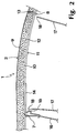
- Fig. 1 shows a perspective view of a plastic cladding according to the invention.
- the plastic cladding is, for example, an instrument panel 1 for Motor vehicles with one facing the passenger compartment Visible side 2.
- the instrument panel 1 there are fan openings 3, recesses 4 for those to be read by the driver Instruments and an opening 5 for the steering wheel column intended.
- cover area 6 On the passenger side of the instrument panel 1 is a dashed line indicated cover area 6 provided by a Airbag is inflatable.
- the lid area 6 is from a fold groove 7 indicated by dashed lines, to which one Tear seam 8 connects, delimited.
- the tear seam 8 tears open.
- the lid area 6 folds over the groove 7 in the Passenger compartment and thus allows the airbag itself to expand the passenger compartment.
- the length of the groove 7 is generally two to four decimeters, while the width of the lid area 6 is two to three decimeters.
- the air bag device comprising the lid area 6 must meet high requirements. Tearing open the Tear seam 8 must take place within milliseconds. To open and open the lid area 6 are only minimum forces of a few 100 Newtons are permitted. To injuries to prevent people from being blown open there are no fragments of the lid area 6, and the lid area 6 must be precisely determined Carry out movement. Because the recognizable existence of an airbag often for aesthetic reasons is perceived as unpleasant, the presence of the Cover area 6 may not be visually recognizable. At the same time the specifications require receipt of these Properties even under unfavorable environmental conditions over a Long period of time.
- Fig. 2 shows a cross section along the section line II-II in Fig. 1.
- Fig. 2 is the thickness of the instrument panel 1 greatly exaggerated.
- the 1 is the visible side 2 of an outer skin 9 is formed.
- a carrier 10 which is an inside 11 of the instrument panel 1 forms.
- the lid area 6 delimiting tear seam 8 comprises a groove-like, in the Carrier 10 and the foam material 12 introduced franking 13.
- the fold groove 7 around which the cover area 6 can be opened, is introduced into the carrier 10.
- On the inside 11 is in the vicinity of the groove 7 am
- Cover area 6 a hinge brace 14 attached has an expansion fold 15 and the one with the frame 16 connected to the body of the motor vehicle is attached.
- the hinge strut 14 guides the lid area 6 when the Airbag bursts open the tear seam 8.
- By stretching the Expansion fold 15 it is possible for the cover area 6 when the airbag inflates, one in the passenger compartment to perform directed movement. This is done the bursting over the entire length of the tear seam 8 essentially at the same time.
- the opening process takes place much faster.
- the hinge strut 14 by a belt made of a textile material replaced.
- the receiving space for the airbag is from guide surfaces 17 formed.
- the inside is expediently 11 facing upper edges 18 of the guide surfaces 17 offset inwards with respect to the lid area 6, damage to the airbag during the expansion process to prevent.
- the outer skin 9 is made in this embodiment Polyvinylchloride manufactured in a rotary sintering process and about 1 to 1.5 millimeters thick, whereas the Carrier 10 made of polycarbonate, acrylonitrile butadiene styrene or injection molded polypropylene and a thickness of has about 2.5 millimeters.
- the outer skin 9 and the Carriers 10 are at a distance of 6 millimeters. That in the space between the outer skin 9 and Foam material 12 located on carrier 10 is polyurethane.
- Fig. 3 shows an enlarged cross section through the Tear seam 8.
- the cover strip 20 is made of paper or a other low strength porous material such as a foam material or suitable Made of foil material.
- the cover strip 20 is held by holding strips 21 which are laterally spaced run to the tear groove 19.
- the holding strips 21 exist made of the same material as the outer skin 9 and on the outer skin 9 by welding or gluing attached.
- the foam material 12 franked 13 introduced is the embodiment shown Width of the franking 13 in the carrier 10 about one millimeter, while the width of the franking in the foam material 12 is less than a millimeter.
- the width the tear groove 19 is approximately 0.5 millimeters.
- the Postage 13 has a bottom 22 which is in the Distance of approximately one millimeter from the cover strip 20 located.
- the franking 13 is along the tear seam 8 interrupted by webs that oppose the lid area 6 secure an unintentional impression.
- the cover strip 20 is used in the manufacture the tear groove 19 is glued by the foam material 12 to prevent.
- the cover strip is 20th porous and allows the exchange of substances between Outer skin 9 and foam material 12.
- Such diffusion processes lead to visually perceptible over time Changes on the visible side 2. If this Diffusion processes are prevented at one point, this leads to discoloration or deformation in the long run on the visible side 2, and such a place becomes visible. To ensure the optical uniformity of the To get face 2, it is therefore necessary that for diffusion along the interface between Outer skin 9 and foam material 12 essentially the the same conditions prevail. Because of the permeability of the cover strip 20, the diffusion processes also take place when the cover strip 20th covers the tear groove 19.
- the franking 13 extends not up to the cover strip 20, but runs in the Bottom 22, which is at a distance from the cover strip 20th located.
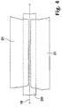
- FIG. 4 shows a top view of the tear groove 19 in FIG. 4. You can see the cover strip covering the tear groove 19 20, the side of the tear groove 19 extending holding strip 21 is held.
- the holding strips 21 reinforce the outer skin 9 along the Tear groove 19 and ensure that the blown open the tear groove 19 forming in the cover strip 20 Crack runs in the area of the tear groove 19. This is ensures that the tear seam 8 tears open smoothly.
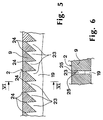
- Fig. 5 shows a longitudinal sectional view through the outer skin 9 along the tear groove 19.
- the tear groove 19 is in Direction of the visible side 2 by itself in periodic Repeating intervals, triangular in longitudinal section Recesses 23 deepened, which taper to tips 24.
- the periodic distance between the recesses 23 is this embodiment 1 to 2.5 millimeters. In the Corner area of the lid area 6 decreases Distance of the recesses 23 to values less than 1 Millimeter. The distance between the visible side 2 and the tips 24 of the recesses 23 in this Embodiment about 0.4 to 0.5 millimeters.
- the outer skin 9 consequently comprises in the area of the tear groove 19 three zones.
- a completely undiminished zone forms the visible side 2.
- To the completely unimpaired Zone is followed by a partially weakened, which in a completely weakened passes.
- FIG. 6 shows a cross section through the outer skin 9 along the section line VI-VI in Fig. 5. It can be seen the same width dimensions towards visible side 2 of the recesses 23. It can also be seen that in this preferred embodiment, the oblique running bottom of the recesses 23 not of round, but is limited by sharp edges 25. This sharp edges 25 can be easily with With the help of a toothed and ground on the teeth Form knife that for punching the tear groove 19 and the Recesses 23 is used to generate. For the production the recesses 23 can also be used Use milling processes that use laser light.
- the sharp edges make cracking easier.
- the inflating airbag initially bulges the lid area 6 to the outside.
- the tear seam 8 a tensile load acting transversely to the tear seam 8 exposed.
- the opening 6 occurring tensions concentrate preferentially the sharp edges 25. This will be the tearing open the tear groove 19 preceding formation of micro cracks favored. Since the tips 24 of the recesses 23 to close to the visible side 2, form in Area of the tips 24 of the recesses 23 close to the Visible side 2 micro-crack centers, which eventually combine into a smooth crack along the tear groove 19.
- the outer skin 9 is only weakened to a fraction of a millimeter. However, remains over the majority of the tear groove 19 the material thickness of the outer skin 9 large. This is ensures that the tear groove 19 even over a long period and under unfavorable climatic conditions and operating conditions not visible on visible side 2 is.
- the triangular recesses 23 result in a particularly smooth tearing of the tear groove 19.
- 19 does not necessarily have to be triangular Recesses 23 be deepened.
- different designed recesses for example with arcuate Longitudinal cuts are possible.
- the recesses 23 can also both with respect to the longitudinal section as well as narrow in cross section.
- the tear groove 19 Visible more quickly over time, but for that the lid area 6 can be blown open with less force.
- the Outer skin for example, in the rotary sintering process manufactured.
- Another option is the outer skin 9 by deep drawing from semi-finished film.
- the recesses 23 with the help of Laser light can be introduced into the outer skin 9. after the Recesses 23 have been created in the outer skin 9, the tear groove 19 is covered with the cover strip 20 and the holding strips 21 by gluing or welding attached to the outer skin 9.
- FIG. 7 is a cross-section through a not to scale modified embodiment of the instrument panel 1 from Fig. 1.
- the Cover area 6 delimited by a circumferential tear seam 26.
- the tear seam 26 is in several places from in webs not shown in the drawing interrupted, an unintentional breaking out of the lid area 6 prevent.
- the tear seam 26 encompasses the outer skin 9 the instrument panel 1 recesses 23, on the one through a cut in the foam material 12 introduced, continuous franking 27 connects.
- the franking 27 goes into a in the area of the carrier 10 milled recess 28 over.
- On the inside 11 is a circumferential support frame on the instrument panel 1 29 attached, the cover area 6 against one secures unintentional impressions.
- one is off a tether 30 produced.
- One end of the tether 30 is on the Inner side 11 of the lid area 6 and the other end of the tether 30 is on the inside 11 of the instrument panel 1 outside the lid area 6 with the help an ultrasound, radio frequency
- Fig. 8 shows an enlarged section through the Cross section in Fig. 7.
- the Recesses 23 and the franking 27 are clear for the sake of Fig. 8 with a large opening width shown.
- the outer skin 9 as well Foam material 12 is elastic, close the Recesses 23 and the franking 27 in general again after using cutting or piercing tools have been produced.
- the recesses 23 with the help of those described in more detail below Piercing needles and the franking 27 with the help of Cutting tools created.
- the recess 28 in the carrier However, 10 is usually milled out.
- Fig. 9 shows a further modified embodiment the instrument panel 1 from Fig. 7.
- This embodiment is characterized in that the Recesses 23 in the outer skin 9 a variety of continue individual recesses 31, which are from Carrier 10 through the foam material 12 to the outer skin 9 extend.
- the recesses 23 and 31 are through Punctures in the instrument panel 1 in one operation created, which makes the manufacture of the instrument panel 1 is significantly simplified.
- FIG. 10 shows a longitudinal section through the outer skin 9 of the embodiments shown in Figs. 8 and 9.
- these exemplary embodiments are absent to the embodiment shown in Fig. 5 the tear groove 19, which additionally weakens the outer skin 9.
- 11 shows a longitudinal section through a modified embodiment.
- this embodiment are arcuate in the outer skin 9 Recesses 23 introduced.
- 11 is intended to clarify be there for good breaking behavior less relevant to the respective longitudinal profile.
- For a good breaking behavior is the presence of sharp ones Edges much more important. So the embodiment has in Fig. 11 as the embodiments in the 5 and 10 on sharp edges 33, on which voltage peaks occur when the tear seam 26 on train is loaded so that those crossing the tear seam 26 Concentrate lines of tension along the edges 33.
- FIG. 12 shows a cross-sectional profile through the outer skin 9 of the embodiment shown in FIG. 10.
- the dashed lines indicate tension lines 34 which concentrate in the area of the edges 32. Thereby there are microcracks in the area of the edges 32, which finally along the tear seam 26 to a continuous Unite crack.
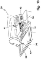
- FIG 13 shows a modified sewing device 35, with which the recesses 23 can be introduced into the outer skin 9 are.
- the outer skin 9 on a X-Y table 36 clamped.
- the X-Y table 36 is over Struts 37 on one shown only partially in FIG Drive mechanism 38 attached to the X-Y table 36 is movable in the X and Y directions.
- a presser foot 39 holds down the outer skin 9 while a piercing needle 40 the recesses 23 in the clamped on the X-Y table Introduces outer skin 9.
- the penetration depth is adjustable via a control knob 41.
- Another Control button 42 is used to set the stitch spacing.
- the piercing needle 40 is a ground, flat needle, if possible with its flat side parallel to the tear seam 8 or 26 to be created is to be aligned. For this reason, a modified, Embodiment not shown in the drawing the X-Y table rotates around a Z axis in order to the production of curved tear seams 8 or 26 too enable.
- the embodiment is the piercing needle 40 depending on the working direction pivotable so that the flat side is always is aligned parallel to the tear seam 8 or 26.
- the outer skin 9 is foamed with the carrier 10 and then the franking 13 in the foam material 12 or 27 incised and the recesses 28 in the Beam 10 milled out.
- the sewing device 35 Since only objects are processed with the sewing device 35 which lie flat on the X-Y table 36, the sewing device 35 is not suitable for production of the embodiment shown in Fig. 9, because at this embodiment, the recesses 23 and 31st only after foaming into the already formed one Instrument panel 1 are introduced. After foaming but already shows the instrument panel 1 final shape and thus does not represent a flat Object.
- FIG. 14 shows an exemplary embodiment of an articulated arm robot 43, who is going to edit the domed Instrument panels 1 is suitable.
- the articulated arm robot 43 has via a base 44, on which one over a Drive device 45 actuated guide arm 46 movable is stored.
- the guide arm 46 holds a work arm 47, which at its front end over a die Piercing needle 40 has needle head 48. With the Puncturing needle 40, an instrument panel 1 can be processed, the pressing devices, not shown, to a Bracket 49 is pressed.
- the use of the piercing needle 40 in the case of FIGS. 13 and 14 shown devices has the advantage that during the manufacture of the plastic cladding 1 the state of the piercing needle 40 slightly with an image processing Security device can be monitored.
- the needle tip 50 is ground and has cutting edges 51 and Cutting surfaces 52 on.
- FIG. 16 shows a cross-sectional profile through the needle tip 50 in Fig. 15. You can see the diamond-like, sharp-edged profile of the needle tip 50.
- the needle tip 50 is aligned so that the longitudinal axis of the cross-sectional profile is parallel is aligned to the tear seam 8.
- FIG. 17 shows a further exemplary embodiment of a Needle tip 50.
- This needle tip is parallel in the direction 8 narrower to the tear seam, but thicker with respect to it the direction transverse to the tear seam 8. Consequently, with of the piercing needle 40 shown in FIG. 17 per unit length carried out a large number of punctures become. But for this the piercing needle 40 is compared to the embodiment shown in FIG Piercing needle 40 much more robust.
- Such a needle is also suitable for use in the articulated robot 43 in the embodiment shown in Fig. 9 Instrument panel 1 to introduce the recesses 23 and 31.
- a device is conceivable in which the piercing needles 40 first serve as a drill to work on the finished instrument panel 1 first pierce the carrier 10. Then in such a device Piercing needles 40 stopped, piercing needles 40 with their Flat side aligned parallel to the tear seam 8 and the Recesses 23 created in the outer skin 9.
Landscapes
- Engineering & Computer Science (AREA)
- Mechanical Engineering (AREA)
- Chemical & Material Sciences (AREA)
- Combustion & Propulsion (AREA)
- Transportation (AREA)
- Air Bags (AREA)
- Perforating, Stamping-Out Or Severing By Means Other Than Cutting (AREA)
Description
- Fig. 1
- eine perspektivische Ansicht einer Kunststoffverkleidung mit gestrichelt angedeuteten Schwachstellen;
- Fig. 2
- einen nicht maßstäblichen Querschnitt durch die Kunststoffverkleidung entlang der Schnittlinie II-II in Fig. 1;
- Fig. 3
- einen vergrößerten Querschnitt durch eine die Schwachstelle bildende Reißnaht, die eine in eine Außenhaut der Kunststoffverkleidung eingebrachte Reißnut umfaßt;
- Fig. 4
- eine Draufsicht auf eine mit einem Abdeckstreifen abgedeckte Reißnut;
- Fig. 5
- eine vergrößerte Längsschnittansicht entlang der Reißnut;
- Fig. 6
- eine vergrößerte Querschnittsansicht entlang der Schnittlinie VI-VI in Fig. 5;
- Fig. 7
- einen nicht maßstäblichen Querschnitt durch ein weiteres Ausführungsbeispiel der Kunststoffverkleidung aus Fig. 1;
- Fig. 8
- einen vergrößerten Ausschnitt aus dem Querschnitt in Fig. 7;
- Fig. 9
- einen vergrößerten Ausschnitt aus einem Querschnitt durch ein weiteres Ausführungsbeispiel der Kunststoffverkleidung aus Fig. 1;
- Fig. 10
- einen vergrößerten Längsschnitt durch in die Außenhaut der Kunststoffverkleidung eingebrachte Ausnehmungen;
- Fig. 11
- einen vergrößerten Längsschnitt durch eine weitere abgewandelte Ausgestaltung der in die Außenhaut der Kunststoffverkleidung eingebrachten Ausnehmungen;
- Fig. 12
- einen Querschnitt durch die Ausnehmungen in Fig. 11;
- Fig. 13
- eine perspektivische Ansicht einer zur Herstellung der Kunststoffverkleidung verwendeten, abgewandelten Nähmaschine;
- Fig. 14
- eine perspektivische Ansicht eines zur Herstellung der Kunststoffverkleidung verwendeten Knickarmroboters;
- Fig. 15
- eine Seitenansicht einer zur Herstellung der Kunststoffverkleidung verwendeten Stechnadel;
- Fig. 16
- einen Querschnitt durch die Stechnadel aus Fig. 15;
- Fig. 17
- eine Seitenansicht auf ein weiteres Ausführungsbeispiel der Stechnadel; und
- Fig. 18
- einen Querschnitt durch die Stechnadel aus Fig. 17.
Claims (20)
- Kunststoffverkleidung mit einer dem Fahrgastraum zugewandten, von einer Außenhaut (9) gebildeten Sichtseite (2) und einer der Sichtseite (2) entgegengesetzten Innenseite (11) sowie mit einem durch einen Luftsack aufsprengbaren Deckelbereich (6), der von einer Vielzahl von Schwachstellen (7, 8, 26) gebildet ist, wobei wenigstens eine Schwachstelle (8, 26) zumindest abschnittsweise eine Vielzahl von scharfkantigen, von der Innenseite (11) aus in die Kunststoffverkleidung eingebrachten Ausnehmungen (23) aufweist, dadurch gekennzeichnet, daß die Schwachstelle (8, 26) von der Innenseite (11) aus in Richtung der Sichtseite (2) in die Außenhaut (9) eingebrachte, im Abstand zur Sichtseite (2) endende, sich in Richtung der Sichtseite (2) punktuell verengende Ausnehmungen (23) aufweist, deren scharfkantigen Profile bei die Schwachstelle (8, 26) querenden Spannungslinien Spannungsspitzen dicht an der Sichtseite (2) entlang der Schwachstelle (8, 26) verursachen.
- Kunststoffverkleidung nach Anspruch 1, dadurch gekennzeichnet, daß die Schwachstelle (8, 26) eine Reißnut (19) umfaßt, die durch die Ausnehmungen (23) weiter vertieft ist.
- Kunststoffverkleidung nach Anspruch 1 oder 2, dadurch gekennzeichnet, daß sich die Längenabmessungen der Ausnehmungen (23) entlang der Schwachstelle (8, 26) zur Sichtseite (2) hin verringern und die Breitenabmessungen der Ausnehmungen (23) quer zur Schwachstelle (8, 26) gleichbleiben.
- Kunststoffverkleidung nach Anspruch 1 oder 2, dadurch gekennzeichnet, daß die Längenabmessungen der Ausnehmungen (23) entlang der Schwachstelle (8, 26) gleichbleiben und daß sich die Breitenabmessungen quer zur Schwachstelle (8, 26) verringern.
- Kunststoffverkleidung nach Anspruch 1 oder 2, dadurch gekennzeichnet, daß sich sowohl die Längenabmessungen der Ausnehmungen (23) entlang der Schwachstelle (8, 26) als auch die Querabmessungen der Ausnehmungen (23) quer zur Schwachstelle (8, 26) auf die Sichtseite (2) verringern.
- Kunststoffverkleidung nach einem der vorstehenden Ansprüche, dadurch gekennzeichnet, daß die Kunststoffverkleidung einen die Innenseite (11) bildenden Träger (10) aufweist, wobei zwischen Außenhaut (9) und Träger (10) ein Schaummaterial (12) eingebracht ist.
- Kunststoffverkleidung nach Anspruch 6, dadurch gekennzeichnet, daß die den Deckelbereich (6) bildenden Schwachstellen eine im Träger (10) eingebrachte Falznut (7) und eine sich daran anschließende Reißnaht (8) umfassen, wobei der Deckelbereich (6) entlang der Reißnaht (8) aufsprengbar und entlang der Falznut (7) ausschwenkbar ist.
- Kunststoffverkleidung nach Anspruch 6, dadurch gekennzeichnet, daß der Deckelbereich (6) von einer umlaufenden Reißnaht (26) gebildet ist.
- Kunststoffverkleidung nach Anspruch 7 oder 8, dadurch gekennzeichnet, daß die Reißnaht (8, 26) von einer Vielzahl von in periodischen Abständen in die Kunststoffverkleidung eingebrachten und sich von der Innenseite (11) der Kunststoffverkleidung bis in die Außenhaut (9) erstreckenden Ausnehmungen (31, 23) gebildet ist.
- Kunststoffverkleidung nach Anspruch 7 oder 8, dadurch gekennzeichnet, daß die Reißnaht (8, 26) eine in die Außenhaut (9) von der Außenseite her eingebrachte, durchgehende Reißnut (19) aufweist, die durch die in periodischen Abständen in die Außenhaut (9) eingebrachten und im Längsschnitt entlang der Reißnut (19) dreieckförmigen Vertiefungen (23), die in Spitzen (24) auslaufen, weiter vertieft ist.
- Kunststoffverkleidung nach Anspruch 10, dadurch gekennzeichnet, daß sich an die Reißnut (19) eine sich durch das Schaummaterial (12) bis zur Innenseite (11) erstreckende Freimachung (27) anschließt.
- Kunststoffverkleidung nach Anspruch 10, dadurch gekennzeichnet, daß die Reißnut (19) durch wenigstens einen Abdeckstreifen (20) abgedeckt ist, der von an der Außenhaut (9) längs der Reißnut (19) befestigten Haltestreifen (21) gehalten ist.
- Kunststoffverkleidung nach Anspruch 12, dadurch gekennzeichnet, daß das Schaummaterial (12) und der Träger (10) im Bereich der Reißnut (19) durch eine Freimachung (13) geschwächt sind, deren Boden (22) sich im Abstand zum Abdeckstreifen (20) befindet.
- Kunststoffverkleidung nach einem der vorstehenden Ansprüche, dadurch gekennzeichnet, daß der Deckelbereich (6) durch wenigstens ein auf der Innenseite (11) des Deckelbereichs (6) angebrachtes Zurückhaltemittel (14, 15, 16, 30) gegen ein Wegschleudern in den Fahrgastraum gesichert ist.
- Verfahren zur Herstellung einer Kunststoffverkleidung nach Anspruch 1, dadurch gekennzeichnet, daß die Ausnehmungen (23, 31) durch eine scharfe Schneidekanten aufweisende Stechnadel (40) in die Kunststoffverkleidung eingebracht werden.
- Verfahren nach Anspruch 15, dadurch gekennzeichnet, daß zunächst in die Außenhaut (9) die Ausnehmungen (23) eingebracht werden, die nachfolgend durch Abdeckstreifen (20) abgedeckt werden, woraufhin die Außenhaut (9) mit einem Träger (10) verschäumt wird.
- Verfahren nach Anspruch 15, dadurch gekennzeichnet, daß zunächst die Ausnehmungen (23) in die Außenhaut (9) eingebracht werden, anschließend die Außenhaut (9) mit dem Träger (10) verschäumt wird und in das Schaummaterial (12) und den Träger (10) eine an die Ausnehmungen (23) anschließende Freimachung (27) eingebracht wird.
- Verfahren nach Anspruch 15, dadurch gekennzeichnet, daß zunächst die Außenhaut (9) mit dem Träger (10) verschäumt wird und anschließend die Ausnehmungen (23, 31) in die Instrumententafel eingebracht werden.
- Vorrichtung zur Herstellung einer Kunststoffverkleidung nach Anspruch 1, dadurch gekennzeichnet, daß eine Nähvorrichtung (35) mit einer scharfkantigen Stechnadel (40) versehen ist, die gegenüber dem Gegenstand (1, 9), in den die Schwachstellen (8, 26) bildenden Ausnehmungen (23, 31) einzubringen sind, bewegbar ist.
- Vorrichtung nach Anspruch 19, dadurch gekennzeichnet, daß die Stechnadel eine spitz zulaufende, flache Stechnadel (40) mit rautenförmigem Querschnittsprofil ist.
Applications Claiming Priority (3)
| Application Number | Priority Date | Filing Date | Title |
|---|---|---|---|
| DE29511172U DE29511172U1 (de) | 1995-07-14 | 1995-07-14 | Kunststoffverkleidung für mit Luftsackeinrichtungen ausgestattete Fahrzeuge |
| DE29511172U | 1995-07-14 | ||
| PCT/DE1996/000785 WO1997003866A1 (de) | 1995-07-14 | 1996-05-09 | Kunststoffverkleidung für fahrzeuge mit luftsack und vorrichtung und verfahren zu deren herstellung |
Publications (2)
| Publication Number | Publication Date |
|---|---|
| EP0846068A1 EP0846068A1 (de) | 1998-06-10 |
| EP0846068B1 true EP0846068B1 (de) | 1999-09-29 |
Family
ID=8010362
Family Applications (1)
| Application Number | Title | Priority Date | Filing Date |
|---|---|---|---|
| EP96914051A Expired - Lifetime EP0846068B1 (de) | 1995-07-14 | 1996-05-09 | Kunststoffverkleidung für fahrzeuge mit luftsack und vorrichtung und verfahren zu deren herstellung |
Country Status (5)
| Country | Link |
|---|---|
| EP (1) | EP0846068B1 (de) |
| AT (1) | ATE185117T1 (de) |
| DE (2) | DE29511172U1 (de) |
| ES (1) | ES2139353T3 (de) |
| WO (1) | WO1997003866A1 (de) |
Cited By (2)
| Publication number | Priority date | Publication date | Assignee | Title |
|---|---|---|---|---|
| US6402189B1 (en) | 2000-02-15 | 2002-06-11 | Textron Automotive Company, Inc | Airbag door and method for making same |
| US6709007B2 (en) | 2000-02-15 | 2004-03-23 | Collins & Aikman Automotive Company Inc. | Airbag door and method for making same |
Families Citing this family (54)
| Publication number | Priority date | Publication date | Assignee | Title |
|---|---|---|---|---|
| DE19623579B4 (de) * | 1996-06-13 | 2006-04-20 | Adam Opel Ag | Kraftfahrzeug-Armaturentafel aus Kunststoff mit einer Airbag-Abdeckung |
| JP3011888B2 (ja) * | 1996-07-19 | 2000-02-21 | 株式会社イノアックコーポレーション | インストルメントパネルのエアバッグドアの構造 |
| DE19646548C2 (de) | 1996-10-31 | 1998-08-27 | Sommer Allibert Lignotock Gmbh | Innenverkleidungsteil für Kraftfahrzeuge mit Airbag-Ausrüstung |
| DE19715033A1 (de) * | 1997-04-11 | 1998-10-15 | Opel Adam Ag | Innenverkleidungsteil, insbesondere für Kraftfahrzeuge |
| DE19715032B4 (de) * | 1997-04-11 | 2008-04-03 | Adam Opel Ag | Abdeckung für ein Airbag-Modul |
| CZ287371B6 (cs) * | 1997-05-22 | 2000-11-15 | Škoda Auto a. s. | Plastová přístrojová deska |
| DE29720138U1 (de) | 1997-11-13 | 1998-03-19 | TRW Automotive Safety Systems GmbH, 63743 Aschaffenburg | Vorrichtung zum Abdecken eines Airbags |
| DE19800815C1 (de) * | 1998-01-05 | 1999-02-04 | Sommer Allibert Lignotock Gmbh | Verfahren zur Einarbeitung einer unsichtbaren Reißnaht in mit Schaumstoff hinterlegte Kaschierungsfolien |
| DE19801611A1 (de) * | 1998-01-17 | 1999-07-22 | Opel Adam Ag | Innenverkleidungsteil, insbesondere für ein Kraftfahrzeug |
| DE29805295U1 (de) | 1998-03-16 | 1998-05-20 | Sommer-Allibert-Lignotock GmbH, 76744 Wörth | Instrumententafel für ein Kraftfahrzeug |
| DE19815267A1 (de) * | 1998-04-04 | 1999-10-07 | Volkswagen Ag | Airbagaufnahme in einer Instrumententafel eines Kraftfahrzeugs |
| DE19816017A1 (de) * | 1998-04-09 | 1999-10-14 | Volkswagen Ag | Abdeckung für einen in einem Fahrzeug angeordneten Airbag |
| US6453535B1 (en) * | 1998-06-25 | 2002-09-24 | Tip Engineering Group, Inc. | Process for manufacturing an automotive trim piece preweakened to form an air bag deployment opening |
| DE29811739U1 (de) | 1998-07-01 | 1998-08-13 | Delphi Automotive Systems Deutschland GmbH, 42369 Wuppertal | Armaturentafel |
| DE19834384A1 (de) * | 1998-07-30 | 2000-02-10 | Daimler Chrysler Ag | Instrumententafel für ein Kraftfahrzeug |
| DE19837421A1 (de) * | 1998-08-18 | 2000-02-24 | Delphi Automotive Systems Gmbh | Armaturentafel |
| DE19910141A1 (de) * | 1999-03-01 | 2000-09-14 | Petri Ag | Aufreißlinie in Abdeckungen von Airbageinheiten |
| DE19939034A1 (de) * | 1999-08-18 | 2001-02-22 | Trw Automotive Safety Sys Gmbh | Zugeschnittenes Leder für eine Abdeckung eines Insassen-Rückhaltemoduls, Abdeckung, Verfahren zum Zuschneiden des Leders und Vorrichtung hierfür |
| FR2800338B1 (fr) * | 1999-11-02 | 2001-12-14 | Sai Automotive Allibert Ind | Planche de bord a dispositif de crochetage perfectionne et dispositif correspondant |
| US6533314B2 (en) | 1999-12-30 | 2003-03-18 | Delphi Technologies, Inc. | Instrument panel with integral hidden door cover and method of manufacture thereof |
| DE10055546C2 (de) * | 2000-03-10 | 2002-11-28 | Aradex Ag | Airbag-Verkleidung mit Schwächungsstrukturen sowie Verfahren zur Erzeugung der Schwächungsstrukturen |
| JP4184577B2 (ja) * | 2000-07-03 | 2008-11-19 | カルソニックカンセイ株式会社 | 車両用インストルメントパネルの取付構造 |
| DE10061438A1 (de) | 2000-12-09 | 2002-06-27 | Eissmann Gmbh | Überzug für ein Armaturenbrett |
| DE10239261B3 (de) * | 2002-08-22 | 2004-05-13 | Peguform Gmbh & Co. Kg I.Ins. | Airbagabdeckung mit Verstärkung aus einem Kunststoffleichtbauteil |
| US7100941B2 (en) | 2003-02-24 | 2006-09-05 | Collins & Aikman | Pre-weakening of fabric covered airbag doors |
| US7219922B2 (en) * | 2003-05-05 | 2007-05-22 | Lear Corporation | Interior vehicle trim panel |
| DE10341839A1 (de) * | 2003-09-09 | 2005-04-21 | Siemens Ag | Instrumententafel |
| DE10352581A1 (de) * | 2003-11-11 | 2005-06-02 | Volkswagen Ag | Innenverkleidungsteil, insbesondere Instrumententafel für ein Kraftfahrzeug |
| US7121578B2 (en) | 2003-12-22 | 2006-10-17 | Lear Corporation | Trim panel having foam bridge supported hidden tear seam |
| DE102004014942A1 (de) * | 2004-03-26 | 2005-10-20 | Draexlmaier Lisa Gmbh | Airbagabdeckung |
| JP4659382B2 (ja) * | 2004-04-01 | 2011-03-30 | タカタ株式会社 | エアバッグカバーの製造方法 |
| DE102004038314A1 (de) * | 2004-08-05 | 2006-03-16 | Eissmann Gmbh | Überzug für die Abdeckung eines Airbags |
| US7497463B2 (en) | 2004-08-05 | 2009-03-03 | Eissmann Automotive Deutschland Gmbh | Lining for the cover of an airbag |
| DE102004043327A1 (de) * | 2004-09-08 | 2006-03-09 | Bayerische Motoren Werke Ag | Airbaganordnugn für Fahrzeuge |
| US8221843B2 (en) | 2005-02-15 | 2012-07-17 | Lisa Dräxlmaier GmbH | Methods and compositions for coating interior components of motor vehicles and interior components of motor vehicles coated using same |
| DE102005010025B4 (de) | 2005-03-04 | 2008-01-24 | Lisa Dräxlmaier GmbH | Fahrzeugtürverkleidung und Verfahren zu deren Herstellung |
| DE102005010024B4 (de) * | 2005-03-04 | 2015-06-11 | Lisa Dräxlmaier GmbH | Fahrzeugtürverkleidung und Verfahren zu deren Herstellung |
| DE102005013477B4 (de) | 2005-03-23 | 2008-12-04 | Lisa Dräxlmaier GmbH | Kraftfahrzeugverkleidungsteil mit Schwächungsstellen und Verfahren zu dessen Herstellung |
| DE102005034354B4 (de) | 2005-07-22 | 2014-08-28 | Lisa Dräxlmaier GmbH | Airbagabdeckung |
| DE102006003684A1 (de) | 2006-01-24 | 2007-07-26 | Jenoptik Automatisierungstechnik Gmbh | Verfahren zum Erzeugen einer Sollbruchlinie in eine mehrschichtige Airbagabdeckung unter Verwendung eines Lasers |
| CN101336177B (zh) * | 2006-02-02 | 2012-08-08 | 佩古佛姆有限公司 | 气囊封盖 |
| US7798518B2 (en) * | 2006-04-27 | 2010-09-21 | Magna International, Inc. | Trim panel with pre-weakened segment and bridge |
| DE102006021999B3 (de) * | 2006-05-10 | 2007-12-20 | Peguform Gmbh | Verfahren zur Herstellung eines mit einer Öffnungsnut für eine Airbagentfaltungsöffnung versehenen Formteiles |
| DE102007002230A1 (de) * | 2007-01-10 | 2008-07-17 | Benecke-Kaliko Ag | Thermoplastische Folie |
| FR2926763B1 (fr) * | 2008-01-29 | 2010-03-26 | Faurecia Interieur Ind | Element de support comprenant un boitier de coussin gonflable. |
| DE102008036768B4 (de) * | 2008-08-07 | 2013-09-12 | Lisa Dräxlmaier GmbH | Nadelperforation der Airbagreißnaht bei Vakuumkaschierfolien |
| DE102010015256A1 (de) * | 2010-04-13 | 2011-10-13 | Faurecia Innenraum Systeme Gmbh | Airbaganordnung sowie Verfahren zur Herstellung derselben |
| WO2013056707A1 (de) * | 2011-10-17 | 2013-04-25 | Decoma (Germany) Gmbh | Verfahren zur erzeugung von messer- oder laserschwächungen von lederhäutung |
| US9803618B2 (en) | 2011-11-23 | 2017-10-31 | Aktiebolaget Skf | Monitoring and fault prediction in relation to a mechanical component of a rotating system |
| US8651514B2 (en) * | 2012-04-11 | 2014-02-18 | Faurecia Interior Systems, Inc. | Airbag tear seam tape |
| DE102012106238A1 (de) * | 2012-07-11 | 2014-01-16 | International Automotive Components Group Gmbh | Innenverkleidungsteil und Verfahren zu seiner Herstellung |
| DE102019126901A1 (de) * | 2019-10-07 | 2021-04-08 | StreetScooter GmbH | Airbagklappensystem mit Randvertiefungen unterschiedlicher Materialstärke |
| DE202021105215U1 (de) * | 2021-09-28 | 2022-01-18 | Grupo Antolín Ingeniería S.A.U. | Formbaugruppe zur Herstellung eines Armaturenbrettes für ein Fahrzeug und damit hergestelltes Armaturenbrett |
| DE102022111874A1 (de) * | 2022-05-12 | 2023-11-16 | Bayerische Motoren Werke Aktiengesellschaft | Verkleidungsteil und Verfahren zur Herstellung eines Verkleidungsteils |
Family Cites Families (10)
| Publication number | Priority date | Publication date | Assignee | Title |
|---|---|---|---|---|
| JPH0299324A (ja) * | 1988-10-07 | 1990-04-11 | Toyota Motor Corp | エアバック蓋部を有する内装部品の製造方法 |
| US4989896A (en) * | 1988-10-17 | 1991-02-05 | Tip Engineering Group, Inc. | Double door closure for an air bag deployment opening |
| JP2666446B2 (ja) * | 1988-12-26 | 1997-10-22 | タカタ株式会社 | エアーバッグ収納用カバー |
| JP2539939B2 (ja) * | 1990-05-24 | 1996-10-02 | タカタ 株式会社 | エアバッグ収納用カバ― |
| JP2906584B2 (ja) * | 1990-05-24 | 1999-06-21 | タカタ株式会社 | エアバッグ収納用カバー |
| US5072967A (en) * | 1990-07-12 | 1991-12-17 | Davidson Textron Inc. | Instrument panel with invisible airbag deployment door |
| JPH0490942A (ja) * | 1990-08-06 | 1992-03-24 | Nippon Plast Co Ltd | ガスバッグのカバー体 |
| JP3029655B2 (ja) * | 1990-09-18 | 2000-04-04 | 株式会社イノアックコーポレーション | 自動車用エアバックドア表皮の製造方法 |
| US5222760A (en) * | 1990-12-07 | 1993-06-29 | Davidson Textron Inc. | Decorative panel with invisible tear seam |
| JP2945559B2 (ja) * | 1993-03-31 | 1999-09-06 | 株式会社イノアックコーポレーション | エアバッグカバー部を有する車両内装部品の製造方法 |
-
1995
- 1995-07-14 DE DE29511172U patent/DE29511172U1/de not_active Expired - Lifetime
-
1996
- 1996-05-09 EP EP96914051A patent/EP0846068B1/de not_active Expired - Lifetime
- 1996-05-09 WO PCT/DE1996/000785 patent/WO1997003866A1/de not_active Ceased
- 1996-05-09 AT AT96914051T patent/ATE185117T1/de not_active IP Right Cessation
- 1996-05-09 DE DE59603240T patent/DE59603240D1/de not_active Expired - Lifetime
- 1996-05-09 ES ES96914051T patent/ES2139353T3/es not_active Expired - Lifetime
Cited By (3)
| Publication number | Priority date | Publication date | Assignee | Title |
|---|---|---|---|---|
| US6402189B1 (en) | 2000-02-15 | 2002-06-11 | Textron Automotive Company, Inc | Airbag door and method for making same |
| US6709007B2 (en) | 2000-02-15 | 2004-03-23 | Collins & Aikman Automotive Company Inc. | Airbag door and method for making same |
| US6976701B2 (en) | 2000-02-15 | 2005-12-20 | Collins & Aikman Automotive Company Inc. | Airbag door and method for making same |
Also Published As
| Publication number | Publication date |
|---|---|
| DE29511172U1 (de) | 1996-02-01 |
| WO1997003866A1 (de) | 1997-02-06 |
| ATE185117T1 (de) | 1999-10-15 |
| ES2139353T3 (es) | 2000-02-01 |
| EP0846068A1 (de) | 1998-06-10 |
| DE59603240D1 (de) | 1999-11-04 |
Similar Documents
| Publication | Publication Date | Title |
|---|---|---|
| EP0846068B1 (de) | Kunststoffverkleidung für fahrzeuge mit luftsack und vorrichtung und verfahren zu deren herstellung | |
| DE69912524T2 (de) | Verfahren zum Herstellen eines Kraftfahrzeugverkleidungsteils mit Schwächungslinien für eine Airbag-Entfaltungsöffnung | |
| DE69627259T2 (de) | Luftsackabdeckung und Herstellungsverfahren dafür | |
| DE69627578T2 (de) | Airbagabdeckung und Verfahren zu deren Herstellung | |
| DE19819573B4 (de) | Instrumententafel | |
| EP0741062B1 (de) | Airbag-Abdeckung sowie Verfahren zu seiner Herstellung | |
| EP1980455B1 (de) | Verfahren zur Herstellung einer Airbagabdeckung | |
| EP1745989B1 (de) | Airbagabdeckung mit unsichtbare Airbagreisslinie | |
| EP2527208B1 (de) | Airbag-Abdeckung, insbesondere für Airbags in einem Kraftfahrzeug und Verfahren zu deren Herstellung | |
| DE4448050C5 (de) | Verfahren zur Herstellung einer Airbag-Abdeckung | |
| EP1161362B1 (de) | Aufreisslinie in abdeckungen von airbageinheiten | |
| DE102006054592B3 (de) | Unsichtbares Laserschwächen im Materialverbund | |
| EP0849128B1 (de) | Abdeckung für ein Airbag-Modul | |
| EP2233372B1 (de) | Airbag-Anordnung für ein Kraftfahrzeug und Verfahren zur Herstellung einer Airbag-Anordnung | |
| DE10055546C2 (de) | Airbag-Verkleidung mit Schwächungsstrukturen sowie Verfahren zur Erzeugung der Schwächungsstrukturen | |
| EP1970263A2 (de) | Verfahren zur Herstellung eines mindestens zweischichtigen Fahrzeuginnenverkleiungsteils mit integrierter Airbagabdeckung und Fahrzeuginnenverkleidungsteil | |
| EP1750978B1 (de) | Überzug als abdeckung für einen airbag und verfahren zu dessen herstellung | |
| DE4411283C1 (de) | Verfahren zur Herstellung einer dehnungselastischen, als Deckschicht einer Abdeckung für einen aufblasbaren Gassack von Fahrzeugen vorgesehenen Folie | |
| DE10241715B4 (de) | Fahrzeuginnenverkleidungsteil mit einer Schwächung in einer Airbagabdeckung | |
| DE20314281U1 (de) | Schneidwerkzeug zur in-process-Regelung der Restwandstärke bei der Airbagschwächung | |
| DE102021113280A1 (de) | Abdeckung für eine Airbag-Einrichtung, Innenverkleidungsteil und Verfahren zur Herstellung einer Abdeckung | |
| DE10122376A1 (de) | Verfahren und Vorrichtung zum Einbringen einer Schwächung für den Airbagbereich in eine Dekorschicht | |
| EP1392551B1 (de) | Vorrichtung zur abdeckung eines airbags und verfahren zu deren herstellung | |
| EP1077163B1 (de) | Zugeschnittenes Leder für eine Abdeckung eines Insassen-Rückhaltemoduls, Abdeckung, Verfahren zum Zuschneiden des Leders und Vorrichtung hierfür | |
| DE10022641B4 (de) | Verfahren zur Herstellung einer Reißnaht als Sollbruchstelle |
Legal Events
| Date | Code | Title | Description |
|---|---|---|---|
| PUAI | Public reference made under article 153(3) epc to a published international application that has entered the european phase |
Free format text: ORIGINAL CODE: 0009012 |
|
| 17P | Request for examination filed |
Effective date: 19980327 |
|
| AK | Designated contracting states |
Kind code of ref document: A1 Designated state(s): AT BE CH DE ES FR GB LI |
|
| GRAG | Despatch of communication of intention to grant |
Free format text: ORIGINAL CODE: EPIDOS AGRA |
|
| 17Q | First examination report despatched |
Effective date: 19981113 |
|
| GRAG | Despatch of communication of intention to grant |
Free format text: ORIGINAL CODE: EPIDOS AGRA |
|
| GRAH | Despatch of communication of intention to grant a patent |
Free format text: ORIGINAL CODE: EPIDOS IGRA |
|
| RAP1 | Party data changed (applicant data changed or rights of an application transferred) |
Owner name: PEGUFORM GMBH |
|
| GRAH | Despatch of communication of intention to grant a patent |
Free format text: ORIGINAL CODE: EPIDOS IGRA |
|
| GRAA | (expected) grant |
Free format text: ORIGINAL CODE: 0009210 |
|
| AK | Designated contracting states |
Kind code of ref document: B1 Designated state(s): AT BE CH DE ES FR GB LI |
|
| REF | Corresponds to: |
Ref document number: 185117 Country of ref document: AT Date of ref document: 19991015 Kind code of ref document: T |
|
| REG | Reference to a national code |
Ref country code: CH Ref legal event code: EP |
|
| REF | Corresponds to: |
Ref document number: 59603240 Country of ref document: DE Date of ref document: 19991104 |
|
| GBT | Gb: translation of ep patent filed (gb section 77(6)(a)/1977) |
Effective date: 19991109 |
|
| ET | Fr: translation filed | ||
| REG | Reference to a national code |
Ref country code: ES Ref legal event code: FG2A Ref document number: 2139353 Country of ref document: ES Kind code of ref document: T3 |
|
| PG25 | Lapsed in a contracting state [announced via postgrant information from national office to epo] |
Ref country code: LI Free format text: LAPSE BECAUSE OF NON-PAYMENT OF DUE FEES Effective date: 20000531 Ref country code: CH Free format text: LAPSE BECAUSE OF NON-PAYMENT OF DUE FEES Effective date: 20000531 |
|
| PLBE | No opposition filed within time limit |
Free format text: ORIGINAL CODE: 0009261 |
|
| STAA | Information on the status of an ep patent application or granted ep patent |
Free format text: STATUS: NO OPPOSITION FILED WITHIN TIME LIMIT |
|
| 26N | No opposition filed | ||
| REG | Reference to a national code |
Ref country code: CH Ref legal event code: PL |
|
| REG | Reference to a national code |
Ref country code: GB Ref legal event code: IF02 |
|
| PGFP | Annual fee paid to national office [announced via postgrant information from national office to epo] |
Ref country code: GB Payment date: 20040427 Year of fee payment: 9 |
|
| PGFP | Annual fee paid to national office [announced via postgrant information from national office to epo] |
Ref country code: AT Payment date: 20040505 Year of fee payment: 9 |
|
| PGFP | Annual fee paid to national office [announced via postgrant information from national office to epo] |
Ref country code: BE Payment date: 20040608 Year of fee payment: 9 |
|
| PG25 | Lapsed in a contracting state [announced via postgrant information from national office to epo] |
Ref country code: GB Free format text: LAPSE BECAUSE OF NON-PAYMENT OF DUE FEES Effective date: 20050509 Ref country code: AT Free format text: LAPSE BECAUSE OF NON-PAYMENT OF DUE FEES Effective date: 20050509 |
|
| PG25 | Lapsed in a contracting state [announced via postgrant information from national office to epo] |
Ref country code: BE Free format text: LAPSE BECAUSE OF NON-PAYMENT OF DUE FEES Effective date: 20050531 |
|
| BERE | Be: lapsed |
Owner name: *PEGUFORM G.M.B.H. Effective date: 20050531 |
|
| GBPC | Gb: european patent ceased through non-payment of renewal fee |
Effective date: 20050509 |
|
| BERE | Be: lapsed |
Owner name: *PEGUFORM G.M.B.H. Effective date: 20050531 |
|
| PGFP | Annual fee paid to national office [announced via postgrant information from national office to epo] |
Ref country code: FR Payment date: 20110603 Year of fee payment: 16 Ref country code: ES Payment date: 20110524 Year of fee payment: 16 |
|
| PGFP | Annual fee paid to national office [announced via postgrant information from national office to epo] |
Ref country code: DE Payment date: 20110629 Year of fee payment: 16 |
|
| REG | Reference to a national code |
Ref country code: FR Ref legal event code: ST Effective date: 20130131 |
|
| REG | Reference to a national code |
Ref country code: DE Ref legal event code: R119 Ref document number: 59603240 Country of ref document: DE Effective date: 20121201 |
|
| PG25 | Lapsed in a contracting state [announced via postgrant information from national office to epo] |
Ref country code: FR Free format text: LAPSE BECAUSE OF NON-PAYMENT OF DUE FEES Effective date: 20120531 |
|
| PG25 | Lapsed in a contracting state [announced via postgrant information from national office to epo] |
Ref country code: DE Free format text: LAPSE BECAUSE OF NON-PAYMENT OF DUE FEES Effective date: 20121201 |
|
| REG | Reference to a national code |
Ref country code: ES Ref legal event code: FD2A Effective date: 20130820 |
|
| PG25 | Lapsed in a contracting state [announced via postgrant information from national office to epo] |
Ref country code: ES Free format text: LAPSE BECAUSE OF NON-PAYMENT OF DUE FEES Effective date: 20120510 |