EP0846560A2 - Chariot pour cartouche d'encre et tête d'imprimante pour une imprimante à jet d'encre - Google Patents
Chariot pour cartouche d'encre et tête d'imprimante pour une imprimante à jet d'encre Download PDFInfo
- Publication number
- EP0846560A2 EP0846560A2 EP97121343A EP97121343A EP0846560A2 EP 0846560 A2 EP0846560 A2 EP 0846560A2 EP 97121343 A EP97121343 A EP 97121343A EP 97121343 A EP97121343 A EP 97121343A EP 0846560 A2 EP0846560 A2 EP 0846560A2
- Authority
- EP
- European Patent Office
- Prior art keywords
- lock lever
- carriage
- ink
- head
- end portion
- Prior art date
- Legal status (The legal status is an assumption and is not a legal conclusion. Google has not performed a legal analysis and makes no representation as to the accuracy of the status listed.)
- Withdrawn
Links
- 230000001154 acute effect Effects 0.000 claims description 5
- 230000013011 mating Effects 0.000 claims description 5
- 238000003780 insertion Methods 0.000 claims description 4
- 230000037431 insertion Effects 0.000 claims description 4
- 230000006835 compression Effects 0.000 description 3
- 238000007906 compression Methods 0.000 description 3
- 239000013013 elastic material Substances 0.000 description 1
- 239000000463 material Substances 0.000 description 1
- 238000000034 method Methods 0.000 description 1
Images


Classifications
-
- B—PERFORMING OPERATIONS; TRANSPORTING
- B41—PRINTING; LINING MACHINES; TYPEWRITERS; STAMPS
- B41J—TYPEWRITERS; SELECTIVE PRINTING MECHANISMS, i.e. MECHANISMS PRINTING OTHERWISE THAN FROM A FORME; CORRECTION OF TYPOGRAPHICAL ERRORS
- B41J2/00—Typewriters or selective printing mechanisms characterised by the printing or marking process for which they are designed
- B41J2/005—Typewriters or selective printing mechanisms characterised by the printing or marking process for which they are designed characterised by bringing liquid or particles selectively into contact with a printing material
- B41J2/01—Ink jet
- B41J2/17—Ink jet characterised by ink handling
- B41J2/175—Ink supply systems ; Circuit parts therefor
-
- B—PERFORMING OPERATIONS; TRANSPORTING
- B41—PRINTING; LINING MACHINES; TYPEWRITERS; STAMPS
- B41J—TYPEWRITERS; SELECTIVE PRINTING MECHANISMS, i.e. MECHANISMS PRINTING OTHERWISE THAN FROM A FORME; CORRECTION OF TYPOGRAPHICAL ERRORS
- B41J2/00—Typewriters or selective printing mechanisms characterised by the printing or marking process for which they are designed
- B41J2/005—Typewriters or selective printing mechanisms characterised by the printing or marking process for which they are designed characterised by bringing liquid or particles selectively into contact with a printing material
- B41J2/01—Ink jet
- B41J2/17—Ink jet characterised by ink handling
- B41J2/175—Ink supply systems ; Circuit parts therefor
- B41J2/17503—Ink cartridges
- B41J2/17553—Outer structure
-
- B—PERFORMING OPERATIONS; TRANSPORTING
- B41—PRINTING; LINING MACHINES; TYPEWRITERS; STAMPS
- B41J—TYPEWRITERS; SELECTIVE PRINTING MECHANISMS, i.e. MECHANISMS PRINTING OTHERWISE THAN FROM A FORME; CORRECTION OF TYPOGRAPHICAL ERRORS
- B41J2/00—Typewriters or selective printing mechanisms characterised by the printing or marking process for which they are designed
- B41J2/005—Typewriters or selective printing mechanisms characterised by the printing or marking process for which they are designed characterised by bringing liquid or particles selectively into contact with a printing material
- B41J2/01—Ink jet
- B41J2/17—Ink jet characterised by ink handling
- B41J2/175—Ink supply systems ; Circuit parts therefor
- B41J2/17503—Ink cartridges
- B41J2/17513—Inner structure
-
- B—PERFORMING OPERATIONS; TRANSPORTING
- B41—PRINTING; LINING MACHINES; TYPEWRITERS; STAMPS
- B41J—TYPEWRITERS; SELECTIVE PRINTING MECHANISMS, i.e. MECHANISMS PRINTING OTHERWISE THAN FROM A FORME; CORRECTION OF TYPOGRAPHICAL ERRORS
- B41J2/00—Typewriters or selective printing mechanisms characterised by the printing or marking process for which they are designed
- B41J2/005—Typewriters or selective printing mechanisms characterised by the printing or marking process for which they are designed characterised by bringing liquid or particles selectively into contact with a printing material
- B41J2/01—Ink jet
- B41J2/17—Ink jet characterised by ink handling
- B41J2/175—Ink supply systems ; Circuit parts therefor
- B41J2/17503—Ink cartridges
- B41J2/1752—Mounting within the printer
Definitions
- the present invention relates to ink-jet printers and, more particularly to a carriage for an ink cartridge as a source of supply of ink to an ink-jet printhead.
- JP-A 7-246716 discloses an ink-jet printer wherein an ink cartridge and an ink-jet printhead are housed in a carriage.
- the cartridge has a rack.
- the carriage includes a base, a case fixed to the base, a pinion lever and a lock lever.
- the base supports the printhead.
- the lock lever and the pinion lever are pivoted to a pivot support that is fixedly attached to the case.
- the lock lever has a lock lever axis that is disposed in the neighborhood of an upper edge of the case.
- the lock lever has a knob including a hook adapted to engage a predetermined portion of the upper edge of the case.
- the lock lever is formed with a protrusion adapted to contact with a top face of the cartridge.
- the pinion lever includes a pinion.
- the pinion has a pinion axis, about which the pinion lever pivots.
- the pinion axis is so arranged as to cause the pinion to engage the rack upon insertion of the cartridge into the case.
- the pinion lever has a pin cooperating with a groove of the lock lever for conjoint operation therewith.
- a spring biases the pinion lever in such a direction as to separate the pin from the groove of the lock lever, causing the pinion to lift the cartridge towards an elevated position from the upper edge of the case.
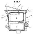
- Fig. 4 illustrates in section a less preferred example of a carriage, generally designated by the reference numeral 1, of an ink-jet printer.
- the carriage 1 houses an ink-jet printhead 2 and an ink cartridge 3.
- a guide rod 7 supports the carriage 1 for reciprocal back and forth motion across a page.
- a lock lever 4 is provided to lock the cartridge 3 to an operative position within the carriage 1.
- the lock lever 4 is pivotally supported via a rotary shaft 4a by a shaft-supporting portion 1a of the carriage 1.
- the lock lever 4 is provided with a downwardly extending knob 4b.
- the knob 4b is curled inwardly to define a hook 4c.
- the hook 4c is elastic enough to engage, in a snap fit manner, a lateral projection on a sidewall of the carriage 1.
- the lock lever 4 is formed with a protrusion 4d.
- the fully drawn line shows the lock lever 4 in a position to close an opening of the carriage 1.
- the protrusion 4d presses the cartridge 3 on a top face thereof into a locked state.
- the cartridge 3 is provided with an ink supply port 5.
- an elastic cap 6 is arranged on the printhead 2.
- the elastic cap 6 is compressed to firmly engage the bottom face of the cartridge 3 to define and seal a cavity around the ink supply port 5.
- the reaction force of the compression of the elastic cap 6 acts on the lock lever 4 via the interface between the top face of the cartridge 3 and the protrusion 4d.
- the edge 1b and the shaft-supporting portion 1a bear all stress that the lock lever 4 is subjected to.
- a component of the reaction force acts on the edge 1b in a direction normal thereto, producing resistance to be overcome in disengaging the hook 4c from the lateral projection 1b.
- a problem with this structure is that if the elastic cap 6 is compressed sufficiently to provide an effective seal around the ink supply port 5, effort required to disengage the hook 4b from the edge 1b may increase to an unacceptably high level.
- a carriage for an ink cartridge as a source of supply of ink to an ink-jet printhead for an ink-jet printer comprising:
- Fig. 1 shows a portion of a typical ink-jet printer sectioned so that a carriage 10 is visible.
- the carriage 10 includes a case 11.
- An ink-jet printhead 12 is mounted to a bottom of the case 11.
- a guide rod 13 extends across a page and guides the carriage 10 so that the printhead 12 moves back and forth on the rod 13 shooting drops of ink as it moves.
- the carriage 10 supports within the case 11 an ink cartridge 14 that contains ink to be supplied to the ink-jet printhead 12.
- the carriage 10 includes a lock lever 20.
- the lock lever 20 is provided to lock the ink cartridge 14 in a predetermined operative position as illustrated in Fig. 1 within the case 11.
- the lock lever 20 is pivotally supported via a rotary shaft 21 by a shaft-supporting portion 11a of the case 11.
- the lock lever 20 includes a cover plate 22.
- the cover plate 22 defines the outer periphery of the lock lever 20 and extends from the one to the opposite end of thereof.
- the lock lever 20 has a knob 23 that is formed with a predetermined surface 25 as best seen in Fig. 2.
- the lock lever 20 is formed with a protrusion 26.
- the fully drawn line shows the lock lever 4 in a position to close an opening 11b for insertion of the cartridge 14.
- the protrusion 26 presses the cartridge 14 on a top face thereof into a locked state.
- the cartridge 14 is provided with an ink supply port 16.
- an elastic cap 17 of elastic material such as rubber is arranged on the printhead 12.
- the cover plate 22 is curled at the opposite end portion downwardly to define the knob 23 and recessed or cut inwards from the inner surface thereof to define the predetermined surface 25.
- the cover plate 22 is formed with an opening or window 24. If desired, the cover plate 22 may be formed with a recess instead of the window 24.
- the window 24 is so dimensioned as to allow insertion of a pawl-like head 15b of a snap hook 15 during the final stage of pivotal movement of the lock lever 20 from an opened position of Fig. 3 to a closed or locked position of Fig. 1.
- the locked position is defined by engagement of the predetermined surface 25 of the knob 23 with a mating surface 15c of the head 15b.
- the hook 15 includes a cantilever 15a.
- the cantilever 15a is provided to hold the head 15b.
- the cantilever 15a is elastically inclined and allowed to snap back toward its unstressed position to put the head 15b into the window 24 during the final stage of movement of the lock lever 20 towards the position of Fig. 1.
- the cantilever 15a is inclined manually to cause the head 15b to move the knob 23 until the window 24 comes into registry with the head 15b.
- the lock lever 20 is elastically bent to allow such movement of the knob 23.
- the cantilever 15a is supported at one end by the case 11 of the carriage 10 and holds the head 15b at the opposite end.
- the cantilever 15a In its unstressed position, the cantilever 15a extends in a spaced relation with a sidewall 16 of the case 11.
- the hook 15 is made of a plastic material and the head 15b is an integral part of and defines the opposite end of the cantilever 15a.
- the cantilever 15a elastically inclines upon application of a force toward the sidewall 16 in one direction to move the head 15b toward the sidewall 16. Subsequently, eliminating the force allows the cantilever 15a to snap back toward its unstressed position to move the head 15b back to its original position.
- Fig. 2 Viewing in Fig. 2, let it be assumed that there is drawn a circle about the axis of the rotary shaft 21 intersecting the predetermined surface 25 of the knob 23 at a predetermined point between one and opposite limits of the surface 25. Then, it may be described that the predetermined surface 25 of the knob 23 is inclined with respect to a reference line segment 50 that is tangential to the circle and extends outwardly from the predetermined point of the surface 25.
- the surface 25 is inclined from the position on the reference line segment 50 through an acute angle ⁇ (alpha).
- the inclined surface 25 faces outwardly as viewed from the axis of the rotary shaft 21 and has leading and trailing limit with respect to a direction of pivotal movement of the lock lever 20 from the position of Fig. 1 to the position of Fig. 3.
- the leading limit is disposed less distant from the axis of the rotary shaft 21 than the trailing limit is.
- the mating surface 15c of the head 15b is inclined by an acute angle with respect to a line segment 52 that is parallel to the reference line segment 50 and extends outwardly from the mating surface 15c.
- the angle of this inclination is the same as the angle ⁇ (alpha) to accomplish a close fitting although the former may differ from the latter as long as deviation from the close fitting is acceptable.
- the cartridge 14 Upon mounting the ink cartridge 14 within the carriage 10, the cartridge 14 is inserted into the carriage 10 through the opening 11b and then the lock lever 20 is pressed toward the case 11 after its counterclockwise rotation about the rotary shalt 21. In the process, the protrusion 26 is pressed against the top face of the cartridge 14.
- the force to which the cartridge 14 is subjected range from 100 g to 2 kg if expressed in terms of a weight which the cartridge 14 supports. Under this condition, the elastic cap 17 is elastically deformed or compressed to effectively seal a cavity around the ink supply port 16.
- the cartridge 14 may be removed from the carriage 10 after releasing the cartridge 14 from its locked position (see Fig. 1) by opening the lock lever 20 to the position as shown in Fig. 3.
- Manual effort required to incline the cantilever 15a in the direction as indicated by the arrow A may be lowered by increasing the length of the cantilever within the range permitted upon designing the carriage.
Landscapes
- Ink Jet (AREA)
- Common Mechanisms (AREA)
- Accessory Devices And Overall Control Thereof (AREA)
Applications Claiming Priority (2)
| Application Number | Priority Date | Filing Date | Title |
|---|---|---|---|
| JP32366296A JP3157731B2 (ja) | 1996-12-04 | 1996-12-04 | インクジェット記録装置 |
| JP323662/96 | 1996-12-04 |
Publications (2)
| Publication Number | Publication Date |
|---|---|
| EP0846560A2 true EP0846560A2 (fr) | 1998-06-10 |
| EP0846560A3 EP0846560A3 (fr) | 1999-05-19 |
Family
ID=18157217
Family Applications (1)
| Application Number | Title | Priority Date | Filing Date |
|---|---|---|---|
| EP97121343A Withdrawn EP0846560A3 (fr) | 1996-12-04 | 1997-12-04 | Chariot pour cartouche d'encre et tête d'imprimante pour une imprimante à jet d'encre |
Country Status (7)
| Country | Link |
|---|---|
| US (1) | US6190010B1 (fr) |
| EP (1) | EP0846560A3 (fr) |
| JP (1) | JP3157731B2 (fr) |
| KR (1) | KR100269200B1 (fr) |
| CN (1) | CN1088653C (fr) |
| AU (1) | AU730970B2 (fr) |
| CA (1) | CA2223342A1 (fr) |
Cited By (3)
| Publication number | Priority date | Publication date | Assignee | Title |
|---|---|---|---|---|
| EP1000751A3 (fr) * | 1998-10-27 | 2000-06-07 | Canon Kabushiki Kaisha | Appareil d'enregistrement |
| WO2003018322A1 (fr) * | 2001-08-22 | 2003-03-06 | Brother Kogyo Kabushiki Kaisha | Dispositif de formation d'image |
| US7585123B2 (en) | 2001-08-22 | 2009-09-08 | Brother Kogyo Kabushiki Kaisha | Image forming apparatus |
Families Citing this family (26)
| Publication number | Priority date | Publication date | Assignee | Title |
|---|---|---|---|---|
| KR100421998B1 (ko) * | 2001-08-09 | 2004-03-12 | 삼성전자주식회사 | 잉크젯 프린터의 잉크 카트리지용 캐리어 |
| KR20030069603A (ko) * | 2002-02-22 | 2003-08-27 | 삼성전자주식회사 | 잉크젯 프린터의 잉크 카트리지 착탈장치 |
| US7384124B2 (en) | 2003-01-17 | 2008-06-10 | Samsung Electronics Co., Ltd. | Carriage for ink cartridge of image forming apparatus |
| US20040256121A1 (en) * | 2003-06-09 | 2004-12-23 | Pollard Lorne R. | Cultivator sweep assembly |
| US7543920B2 (en) * | 2004-01-09 | 2009-06-09 | Videojet Technologies Inc. | System and method for connecting an ink bottle to an ink reservoir of an ink jet printing system |
| US20060012628A1 (en) * | 2004-07-13 | 2006-01-19 | Nu-Kote International, Inc. | Transportation pad for ink cartridge |
| JP2006187898A (ja) * | 2005-01-04 | 2006-07-20 | Funai Electric Co Ltd | インクジェットプリンタ |
| TWI273043B (en) * | 2005-05-05 | 2007-02-11 | Benq Corp | Printer and the ink carrier thereof |
| JP4595870B2 (ja) * | 2006-03-31 | 2010-12-08 | ブラザー工業株式会社 | インクカートリッジ保持部材 |
| JP4631781B2 (ja) * | 2006-03-31 | 2011-02-16 | ブラザー工業株式会社 | インクカートリッジ保持部材 |
| US7419254B1 (en) | 2007-01-30 | 2008-09-02 | Brother Kogyo Kabushiki Kaisha | Ink cartridges |
| JP4858191B2 (ja) | 2007-01-30 | 2012-01-18 | ブラザー工業株式会社 | インクカートリッジ及びカートリッジ収容装置 |
| WO2012173978A1 (fr) | 2011-06-13 | 2012-12-20 | Mycelx Technologies Corporation | Compositions antimicrobiennes viscoélastiques et procédés |
| EP2586618B1 (fr) | 2011-10-31 | 2014-09-24 | Brother Kogyo Kabushiki Kaisha | Appareil d'enregistrement doté d'un dispositif de transport pour un support d'enregistrement |
| EP2586617B1 (fr) | 2011-10-31 | 2014-09-24 | Brother Kogyo Kabushiki Kaisha | Appareil d'enregistrement à mécanisme de convoyage sur support d'enregistrement |
| EP2599635B1 (fr) | 2011-11-30 | 2014-11-05 | Brother Kogyo Kabushiki Kaisha | Dispositif d'éjection d'un liquide |
| JP6003359B2 (ja) * | 2012-07-31 | 2016-10-05 | ブラザー工業株式会社 | 液体吐出装置 |
| US9004655B2 (en) * | 2012-07-31 | 2015-04-14 | Brother Kogyo Kabushiki Kaisha | Liquid ejecting apparatus |
| BR112015005608A2 (pt) * | 2012-09-14 | 2017-07-04 | Funai Electric Co | ejetor de cartucho para cabeças de ejeção de microfluido que abrangem a largura da página |
| JP6205697B2 (ja) * | 2012-09-28 | 2017-10-04 | ブラザー工業株式会社 | 液体吐出装置 |
| JP6454970B2 (ja) * | 2014-03-14 | 2019-01-23 | セイコーエプソン株式会社 | 液体供給装置 |
| JP6862771B2 (ja) * | 2016-11-04 | 2021-04-21 | セイコーエプソン株式会社 | 液体収容ユニットおよび液体噴射装置 |
| JP6794783B2 (ja) * | 2016-11-04 | 2020-12-02 | セイコーエプソン株式会社 | 液体噴射装置 |
| US11260665B2 (en) * | 2017-12-14 | 2022-03-01 | Hewlett-Packard Development Company, L.P. | Print head lock |
| CN107933121A (zh) * | 2017-12-29 | 2018-04-20 | 上海古鳌电子科技股份有限公司 | 一种金融票据打印装置及方法 |
| WO2020069845A1 (fr) * | 2018-10-03 | 2020-04-09 | Memjet Technology Limited | Module d'impression avec mise en prise de carte de circuit imprimé à deux étages |
Family Cites Families (17)
| Publication number | Priority date | Publication date | Assignee | Title |
|---|---|---|---|---|
| JPS5846784B2 (ja) | 1974-08-12 | 1983-10-18 | 日本ビクター株式会社 | ジヨウホウキロクバイタイノ ケンシユツシジタイ |
| JPS57125580A (en) | 1981-01-02 | 1982-08-04 | Ibm | Threshould processing mode switch |
| JP2763310B2 (ja) | 1988-12-29 | 1998-06-11 | キヤノン株式会社 | インクジェットカートリッジ |
| US5230433A (en) | 1992-01-28 | 1993-07-27 | The Procter & Gamble Company | Adult friendly child-resistant attachment for containers used to store potentially dangerous materials |
| JP2925394B2 (ja) * | 1992-03-09 | 1999-07-28 | キヤノン株式会社 | 保管容器 |
| JPH06106730A (ja) * | 1992-09-28 | 1994-04-19 | Canon Inc | インクジェット記録装置 |
| JPH0768777A (ja) | 1993-09-03 | 1995-03-14 | Canon Inc | インクジェット記録装置 |
| JP3428003B2 (ja) | 1994-03-10 | 2003-07-22 | セイコーエプソン株式会社 | キャリッジ |
| US5504513A (en) | 1994-04-25 | 1996-04-02 | Hewlett-Packard Company | Deflection compensation for cartridge carriage with compliant walls |
| EP0927641B1 (fr) | 1994-11-02 | 2002-03-13 | Seiko Epson Corporation | Unité d'enregistrement à jet d'encre |
| US5663751A (en) | 1994-12-22 | 1997-09-02 | Pitney Bowes Inc. | Automatic service station for the printhead of an inkjet printer and method for cleaning the printhead |
| JP3417434B2 (ja) | 1995-01-05 | 2003-06-16 | セイコーエプソン株式会社 | インクジェットプリンタ用インクカートリッジ |
| US5654744A (en) | 1995-03-06 | 1997-08-05 | Hewlett-Packard Company | Simultaneously printing with different sections of printheads for improved print quality |
| JP3324629B2 (ja) * | 1995-03-13 | 2002-09-17 | セイコーエプソン株式会社 | インクジェット式印刷ユニットの保管ケース |
| JPH08258277A (ja) | 1995-03-20 | 1996-10-08 | Fuji Xerox Co Ltd | インクジェット記録ユニット |
| GB2315045B (en) * | 1996-07-05 | 1998-11-25 | Seiko Epson Corp | Ink cartridge and loading mechanism for the ink cartridge |
| JPH10109458A (ja) * | 1996-08-14 | 1998-04-28 | Seiko Epson Corp | インクジェット記録装置における記録ヘッドの位置調整機構 |
-
1996
- 1996-12-04 JP JP32366296A patent/JP3157731B2/ja not_active Expired - Fee Related
-
1997
- 1997-12-03 CA CA002223342A patent/CA2223342A1/fr not_active Abandoned
- 1997-12-03 KR KR1019970065612A patent/KR100269200B1/ko not_active Expired - Lifetime
- 1997-12-04 CN CN97121976A patent/CN1088653C/zh not_active Expired - Lifetime
- 1997-12-04 US US08/985,234 patent/US6190010B1/en not_active Expired - Lifetime
- 1997-12-04 AU AU46872/97A patent/AU730970B2/en not_active Expired
- 1997-12-04 EP EP97121343A patent/EP0846560A3/fr not_active Withdrawn
Cited By (6)
| Publication number | Priority date | Publication date | Assignee | Title |
|---|---|---|---|---|
| EP1000751A3 (fr) * | 1998-10-27 | 2000-06-07 | Canon Kabushiki Kaisha | Appareil d'enregistrement |
| US6312105B1 (en) | 1998-10-27 | 2001-11-06 | Canon Kabushiki Kaisha | Recording apparatus |
| WO2003018322A1 (fr) * | 2001-08-22 | 2003-03-06 | Brother Kogyo Kabushiki Kaisha | Dispositif de formation d'image |
| US7585123B2 (en) | 2001-08-22 | 2009-09-08 | Brother Kogyo Kabushiki Kaisha | Image forming apparatus |
| US7591518B2 (en) | 2001-08-22 | 2009-09-22 | Brother Kogyo Kabushiki Kaisha | Image forming apparatus |
| US8348403B2 (en) | 2001-08-22 | 2013-01-08 | Brother Kogyo Kabushiki Kaisha | Image forming apparatus |
Also Published As
| Publication number | Publication date |
|---|---|
| CA2223342A1 (fr) | 1998-06-04 |
| KR19980063754A (ko) | 1998-10-07 |
| EP0846560A3 (fr) | 1999-05-19 |
| US6190010B1 (en) | 2001-02-20 |
| JP3157731B2 (ja) | 2001-04-16 |
| AU4687297A (en) | 1998-06-11 |
| KR100269200B1 (ko) | 2000-10-16 |
| CN1184033A (zh) | 1998-06-10 |
| CN1088653C (zh) | 2002-08-07 |
| JPH10157162A (ja) | 1998-06-16 |
| AU730970B2 (en) | 2001-03-22 |
Similar Documents
| Publication | Publication Date | Title |
|---|---|---|
| US6190010B1 (en) | Carriage for ink cartridge and printhead for ink-jet printer | |
| US7384124B2 (en) | Carriage for ink cartridge of image forming apparatus | |
| JPS6113990B2 (fr) | ||
| US6695436B2 (en) | Apparatus to remove ink cartridge of ink-jet printer | |
| CN1144508A (zh) | 打印装置的打印头回位机构 | |
| JP2000127427A (ja) | インクジェット記録装置、ホルダー、およびキャリッジ | |
| JPH10264409A (ja) | インクカートリッジおよびインクジェット記録装 置 | |
| GB1596703A (en) | Drive apparatus for magnetic discs | |
| JP2976934B2 (ja) | インクカートリッジとその装填機構 | |
| US7010252B2 (en) | Mounting construction of a toner cartridge for an image forming apparatus | |
| CN217649167U (zh) | 一种打印设备及其翻盖结构 | |
| JP2002254670A (ja) | キャリッジ、およびインクジェット記録装置 | |
| CN108724921B (zh) | 头加压机构和带印刷装置 | |
| US9834019B2 (en) | Recording apparatus | |
| JP2001302073A (ja) | プリンタ | |
| US3924724A (en) | Structure for facilitating interchange of typing elements | |
| JP3917439B2 (ja) | プリンタ | |
| JP2000218822A (ja) | インクジェット記録装置 | |
| EP1090765A1 (fr) | Imprimante à jet d'encre | |
| KR100421998B1 (ko) | 잉크젯 프린터의 잉크 카트리지용 캐리어 | |
| CN113386472A (zh) | 印刷装置、调节装置以及调节方法 | |
| JP2590452Y2 (ja) | プリンタの印字ヘッド支持装置 | |
| US6443553B2 (en) | Printer having one or more print cartridges installed during manufacture | |
| JPH06143774A (ja) | 感熱プリンター及び感熱転写カートリッジ | |
| US6350010B1 (en) | Printer having one or more print cartridges installed during manufacture |
Legal Events
| Date | Code | Title | Description |
|---|---|---|---|
| PUAI | Public reference made under article 153(3) epc to a published international application that has entered the european phase |
Free format text: ORIGINAL CODE: 0009012 |
|
| AK | Designated contracting states |
Kind code of ref document: A2 Designated state(s): DE FR GB IT NL SE |
|
| AX | Request for extension of the european patent |
Free format text: AL;LT;LV;MK;RO;SI |
|
| PUAL | Search report despatched |
Free format text: ORIGINAL CODE: 0009013 |
|
| AK | Designated contracting states |
Kind code of ref document: A3 Designated state(s): AT BE CH DE DK ES FI FR GB GR IE IT LI LU MC NL PT SE |
|
| AX | Request for extension of the european patent |
Free format text: AL;LT;LV;MK;RO;SI |
|
| 17P | Request for examination filed |
Effective date: 19990913 |
|
| AKX | Designation fees paid |
Free format text: DE FR GB IT NL SE |
|
| 17Q | First examination report despatched |
Effective date: 20010308 |
|
| RAP1 | Party data changed (applicant data changed or rights of an application transferred) |
Owner name: FUJI XEROX CO., LTD. |
|
| GRAH | Despatch of communication of intention to grant a patent |
Free format text: ORIGINAL CODE: EPIDOS IGRA |
|
| STAA | Information on the status of an ep patent application or granted ep patent |
Free format text: STATUS: THE APPLICATION IS DEEMED TO BE WITHDRAWN |
|
| 18D | Application deemed to be withdrawn |
Effective date: 20030228 |