EP0846603A1 - Antrieb, insbesondere für eine elektrische Fahrzeugdiebstahlsicherung - Google Patents
Antrieb, insbesondere für eine elektrische Fahrzeugdiebstahlsicherung Download PDFInfo
- Publication number
- EP0846603A1 EP0846603A1 EP97121208A EP97121208A EP0846603A1 EP 0846603 A1 EP0846603 A1 EP 0846603A1 EP 97121208 A EP97121208 A EP 97121208A EP 97121208 A EP97121208 A EP 97121208A EP 0846603 A1 EP0846603 A1 EP 0846603A1
- Authority
- EP
- European Patent Office
- Prior art keywords
- wheel
- axis
- rotation
- actuator
- section
- Prior art date
- Legal status (The legal status is an assumption and is not a legal conclusion. Google has not performed a legal analysis and makes no representation as to the accuracy of the status listed.)
- Granted
Links
- 230000033001 locomotion Effects 0.000 claims abstract description 26
- 230000003100 immobilizing effect Effects 0.000 claims description 6
- 208000031968 Cadaver Diseases 0.000 description 1
- 230000005540 biological transmission Effects 0.000 description 1
- 238000010586 diagram Methods 0.000 description 1
- 238000006073 displacement reaction Methods 0.000 description 1
Images


Classifications
-
- B—PERFORMING OPERATIONS; TRANSPORTING
- B60—VEHICLES IN GENERAL
- B60R—VEHICLES, VEHICLE FITTINGS, OR VEHICLE PARTS, NOT OTHERWISE PROVIDED FOR
- B60R25/00—Fittings or systems for preventing or indicating unauthorised use or theft of vehicles
- B60R25/01—Fittings or systems for preventing or indicating unauthorised use or theft of vehicles operating on vehicle systems or fittings, e.g. on doors, seats or windscreens
- B60R25/02—Fittings or systems for preventing or indicating unauthorised use or theft of vehicles operating on vehicle systems or fittings, e.g. on doors, seats or windscreens operating on the steering mechanism
- B60R25/021—Fittings or systems for preventing or indicating unauthorised use or theft of vehicles operating on vehicle systems or fittings, e.g. on doors, seats or windscreens operating on the steering mechanism restraining movement of the steering column or steering wheel hub, e.g. restraining means controlled by ignition switch
- B60R25/0215—Fittings or systems for preventing or indicating unauthorised use or theft of vehicles operating on vehicle systems or fittings, e.g. on doors, seats or windscreens operating on the steering mechanism restraining movement of the steering column or steering wheel hub, e.g. restraining means controlled by ignition switch using electric means, e.g. electric motors or solenoids
- B60R25/02153—Fittings or systems for preventing or indicating unauthorised use or theft of vehicles operating on vehicle systems or fittings, e.g. on doors, seats or windscreens operating on the steering mechanism restraining movement of the steering column or steering wheel hub, e.g. restraining means controlled by ignition switch using electric means, e.g. electric motors or solenoids comprising a locking member radially and linearly moved towards the steering column
Definitions
- the invention relates to an actuator, in particular for a electric vehicle anti-theft device.
- the invention relates more particularly to a actuator in which an input movement, which can be supplied for example by an electric motor or by a cable, is transformed into two successive movements of an output shaft: a translation of the tree in a perpendicular direction to its axis and a rotation of the tree around its axis.
- the object of the invention is therefore to propose an actuator to transform a single entry movement into two successive and different movements of a tree actuator output to control a mechanism.
- the invention provides an actuator of the type with wheel and worm, characterized in that the wheel has a control pad which is fixed relative to the wheel and which moves in a control light provided for this purpose in a fixed body of the actuator, in that the light comprises a first straight section, in which the control pad for the wheel slides by authorizing a translation of the wheel according to a direction parallel to the axis of the screw and in which the pad blocks any rotation of the wheel around its axis, and which is extended by a second section in which the skate pivots to allow the rotation of the wheel around its axis while immobilizing it in translation, and in that the output shaft is arranged along the axis of the wheel and is integral in rotation of the wheel.
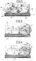
- the actuator 10 which is shown in Figure 1 essentially comprises a worm 12 which is mounted at rotation about its longitudinal axis A1 in a housing 14 of the actuator 10 and which meshes with a wheel 16 of the axle transverse A2 perpendicular to the axis A1 of the screw 12.
- the screw endless 12 is driven by an electric motor 13 but the invention can also be implemented with any type of means for driving the screw 12. This can thus be driven by a simple crank or by a flexible cable rotating motion transmission.
- the wheel 16 is guided along the direction of its axis A2 between two opposite side walls 18, 20 of the housing 14 and it is integral with an output shaft 22 which is arranged according to its axis A2 and which is integral in rotation with the wheel 16.
- the actuator 10 also includes a control pad 24 and a guide bearing 26 which are each mounted on one side of the wheel 16 on the output shaft 22.
- the control pad 24 is integral in rotation with the wheel 16 and it is received in a control light 28 arranged in one of the side walls 18 of the housing 14.
- the guide bearing 26 is rotatably mounted on the shaft 22 and it is received in a guide light 30 arranged in the other 20 of the walls side of the case.
- the light from guide 30 is a rectilinear light which extends parallel to the longitudinal direction of the screw 12. It has two opposite longitudinal edges 32 between which the bearing guide 26 is received.
- the bearing 26 has two faces longitudinal straight lines 34 which cooperate with the edges longitudinal 32 of light 30 to prevent the bearing from guide 26 to rotate in the corresponding light 30.
- the bearing 26 is thus capable of sliding longitudinally in the light 30.
- the light of control 28, in which the control shoe 24 is received has two straight sections 36 and circular sections 38 which are follow longitudinally from back to front according to the direction of the axis A1 of the worm screw 12.
- the first section 36 of the control light 28 is a straight section which extends parallel to the light of guide 30 and which also has two longitudinal edges opposites 40 with which two longitudinal faces cooperate rectilinear and parallel 42 of the control pad 24.
- the shoe 24 is capable of sliding longitudinally, in both directions, without being able to turn around the axis A2 of the output shaft 22.
- the second section 38 of the control light 28 essentially comprises a lateral edge in an arc 44 which spans more than three-quarters of a circle and in which opens the first section 36 of the control light 28.
- the diameter of the second circular section 38 of the light 28 is substantially equal to the largest dimension of the shoe 24 in a direction perpendicular to the axis A2 of the wheel 16 so that the latter can pivot around the axis A2 at inside the second section 38.
- the wheel 16 is arranged on the screw 12 so that the shoe control 24 is received in the first section 36 of the light 28, and more particularly in the end rear longitudinal 35 of the first section 36 which is opposite to its front end 37 by which it opens into the second section 38.
- the control pad 24 is then immobilized in rotation about the axis A2 by its longitudinal faces 42 which cooperate with the longitudinal edges 40 of the first section 36.
- the wheel moves longitudinally from back to front, i.e. from the left to the right considering the figures, taking with it the output shaft 22.
- the shoe command 24 leaves the first section 36, it is fully received inside the second section 38 and it is supported by a front longitudinal end against the circular edge 44 of the latter so as to prevent any translation additional towards the front of the shoe 24, and therefore of the wheel 16 and the output shaft 22.
- the rotation of the shoe 24 in the second section 38 of the control light 28 is limited by two stops 46, 48 which are arranged so as to limit the angular travel of the shoe, and therefore of the output shaft 22, in the second section 28.
- This abutment face 46 is arranged so that the bearing 41 performs a quarter turn between its positions shown in Figures 3 and 4 respectively.
- the pad 24 is then no longer capable of pivoting around the axis 32 nor to translate inside the second section 28 so that the wheel 16 is completely immobilized. It is then necessary to stop the engine 13 either by detecting the arrival of the pad 24 in this position, either by detecting a sudden variation in the torque supplied by the electric motor 13.
- the shoe 24 In this position, the shoe 24 is oriented so that its longitudinal faces 42 are oriented parallel to the longitudinal edges 40 of the first section 36 of the lumen control 28, opposite the front longitudinal end 37 of the first section 36 which opens into the second section 38.
- the shoe 24 By the action of the second stopper 48, the shoe 24 is prevented pivot around its axis A2 so that the movement of rotation of screw 12 is transformed into a movement of translation; from back to front, from the wheel 16.
- the shoe 24 tends then to engage again in the first section 38 of the control light 28 and thus continues until arrival in its initial position shown in Figure 2.
- the actuator according to the invention therefore makes it possible to use the only rotary movement of the worm, without change of direction, to cause two consecutive movements of the output shaft 22.
- FIG. 5 shows an anti-theft device for a motor vehicle steering column 50.
- Column 50 has a column shaft on which a wheel is mounted tooth 52 which is coaxial with it and which is integral therewith rotation.
- the anti-theft device essentially comprises a pinion 54, of axis A4 parallel to the axis A3 of column 50, which is mounted at rotation around its axis A4 on a sliding support 56.
- the sliding support 56 moves parallel to one direction tangent of the ring gear 52 between a disengaged position (not shown) and an engaged position shown in the Figure 5, in which the pinion 54 meshes with the crown 52.
- a device 58 for immobilizing the pinion 54 in rotation about its axis A4 is implemented.
- the immobilizer 58 which can be, for example, a multi-plate clutch torque limiter arranged along the axis A4 of the pinion 54 is controlled by by means of two cams 60 which are rotatably mounted by compared to slide 56 around a perpendicular axis A5 and concurrent with axes A3 and A4 of column 10 and of the pinion 54.
- the coach 10 allows to control with a single motor all displacements necessary to put in the state of condemnation of the lock.
- the output shaft 22 can both control the translation of the sliding support 56 and the rotation of the cams 60, using the only electric motor 13.
- the guide bearing 26 can be connected the actuator 10 to the slide 56 to ensure that the forces induced on the output shaft 22 and on the wheel 16 during of the translation are symmetrical with respect to the screw 12.
Landscapes
- Engineering & Computer Science (AREA)
- Mechanical Engineering (AREA)
- Gear Transmission (AREA)
- Steering Controls (AREA)
- Lock And Its Accessories (AREA)
- Transmission Devices (AREA)
Applications Claiming Priority (2)
| Application Number | Priority Date | Filing Date | Title |
|---|---|---|---|
| FR9615064A FR2756896B1 (fr) | 1996-12-05 | 1996-12-05 | Actionneur, notamment pour un antivol electrique de vehicule automobile |
| FR9615064 | 1996-12-05 |
Publications (2)
| Publication Number | Publication Date |
|---|---|
| EP0846603A1 true EP0846603A1 (de) | 1998-06-10 |
| EP0846603B1 EP0846603B1 (de) | 2001-06-27 |
Family
ID=9498449
Family Applications (1)
| Application Number | Title | Priority Date | Filing Date |
|---|---|---|---|
| EP19970121208 Expired - Lifetime EP0846603B1 (de) | 1996-12-05 | 1997-12-03 | Antrieb, insbesondere für eine elektrische Fahrzeugdiebstahlsicherung |
Country Status (4)
| Country | Link |
|---|---|
| EP (1) | EP0846603B1 (de) |
| DE (1) | DE69705377T2 (de) |
| ES (1) | ES2160882T3 (de) |
| FR (1) | FR2756896B1 (de) |
Cited By (3)
| Publication number | Priority date | Publication date | Assignee | Title |
|---|---|---|---|---|
| FR2799709A1 (fr) * | 1999-10-19 | 2001-04-20 | Valeo Securite Habitacle | Antivol electrique de direction de vehicule automobile |
| EP1078829A3 (de) * | 1999-08-26 | 2003-05-07 | METHODE ELECTRONICS, Inc. | Lenksperre mit Sicherheitsvorrichtung |
| EP2476592A1 (de) * | 2011-01-13 | 2012-07-18 | Valeo Sicherheitssysteme GmbH | Diebstahlsicherung für Lenksäule eines Kraftfahrzeugs |
Families Citing this family (1)
| Publication number | Priority date | Publication date | Assignee | Title |
|---|---|---|---|---|
| DE102004001511B4 (de) * | 2004-01-09 | 2015-02-19 | Continental Automotive Gmbh | Vorrichtung zum Arretieren einer Lenksäule eines Kraftfahrzeuges |
Citations (3)
| Publication number | Priority date | Publication date | Assignee | Title |
|---|---|---|---|---|
| US3659377A (en) * | 1970-04-01 | 1972-05-02 | Mattel Inc | Checkout stand toy with turntable drive |
| JPH04131557A (ja) * | 1990-06-07 | 1992-05-06 | Asmo Co Ltd | シフトロックアクチュエータ |
| JPH0586761A (ja) * | 1991-09-30 | 1993-04-06 | Harada Ind Co Ltd | ドアロツク装置用アクチユエータ |
-
1996
- 1996-12-05 FR FR9615064A patent/FR2756896B1/fr not_active Expired - Fee Related
-
1997
- 1997-12-03 EP EP19970121208 patent/EP0846603B1/de not_active Expired - Lifetime
- 1997-12-03 ES ES97121208T patent/ES2160882T3/es not_active Expired - Lifetime
- 1997-12-03 DE DE1997605377 patent/DE69705377T2/de not_active Expired - Fee Related
Patent Citations (3)
| Publication number | Priority date | Publication date | Assignee | Title |
|---|---|---|---|---|
| US3659377A (en) * | 1970-04-01 | 1972-05-02 | Mattel Inc | Checkout stand toy with turntable drive |
| JPH04131557A (ja) * | 1990-06-07 | 1992-05-06 | Asmo Co Ltd | シフトロックアクチュエータ |
| JPH0586761A (ja) * | 1991-09-30 | 1993-04-06 | Harada Ind Co Ltd | ドアロツク装置用アクチユエータ |
Non-Patent Citations (2)
| Title |
|---|
| PATENT ABSTRACTS OF JAPAN vol. 016, no. 395 (M - 1299) 21 August 1992 (1992-08-21) * |
| PATENT ABSTRACTS OF JAPAN vol. 017, no. 417 (M - 1457) 4 August 1993 (1993-08-04) * |
Cited By (6)
| Publication number | Priority date | Publication date | Assignee | Title |
|---|---|---|---|---|
| EP1078829A3 (de) * | 1999-08-26 | 2003-05-07 | METHODE ELECTRONICS, Inc. | Lenksperre mit Sicherheitsvorrichtung |
| FR2799709A1 (fr) * | 1999-10-19 | 2001-04-20 | Valeo Securite Habitacle | Antivol electrique de direction de vehicule automobile |
| EP2476592A1 (de) * | 2011-01-13 | 2012-07-18 | Valeo Sicherheitssysteme GmbH | Diebstahlsicherung für Lenksäule eines Kraftfahrzeugs |
| WO2012095246A1 (fr) * | 2011-01-13 | 2012-07-19 | Valeo Sicherheitssysteme Gmbh | Antivol de direction pour vehicule automobile |
| CN103492239A (zh) * | 2011-01-13 | 2014-01-01 | 法雷奥安全系统有限责任公司 | 用于机动车辆的转向锁定装置 |
| US9085274B2 (en) | 2011-01-13 | 2015-07-21 | Valeo Sicherheitssysteme Gmbh | Steering lock for a motor vehicle |
Also Published As
| Publication number | Publication date |
|---|---|
| DE69705377T2 (de) | 2001-10-31 |
| FR2756896A1 (fr) | 1998-06-12 |
| DE69705377D1 (de) | 2001-08-02 |
| EP0846603B1 (de) | 2001-06-27 |
| FR2756896B1 (fr) | 1999-01-22 |
| ES2160882T3 (es) | 2001-11-16 |
Similar Documents
| Publication | Publication Date | Title |
|---|---|---|
| WO2022128987A1 (fr) | Volant de vehicule automobile a jante repliable ou escamotable | |
| EP0846603B1 (de) | Antrieb, insbesondere für eine elektrische Fahrzeugdiebstahlsicherung | |
| FR2652318A1 (fr) | Retroviseur exterieur pour vehicule. | |
| EP0081025B1 (de) | Rotationsservomechanismus, insbesondere für eine Fahrzeuglenkung | |
| EP0764565B1 (de) | Angetriebenes Lenkradschloss für Kraftfahrzeuge | |
| FR2690403A1 (fr) | Ensemble de colonne de direction réglable en position pour véhicule automobile. | |
| FR2810422A1 (fr) | Mecanisme de verrouillage d'un arbre de transmission d'un vehicule | |
| EP1214233B1 (de) | Feststellbremse, insbesondere für ein fahrzeug mit elektrischem antrieb | |
| EP2659076B1 (de) | Steuerungsvorrichtung für ein fahrzeugtürverriegelungssystem | |
| FR2769037A1 (fr) | Dispositif de verrouillage comportant un doigt de transmission commande par came | |
| FR2970311A1 (fr) | Frein de parking d'une boite de vitesses | |
| FR2596096A1 (fr) | Dispositif d'entrainement d'une tige de commande d'actionneur de serrure notamment de serrure de porte de vehicule automobile, et serrure equipee d'un tel dispositif | |
| FR2523532A1 (fr) | Dispositif antivol pour un arbre tournant, notamment pour la colonne de direction d'un vehicule automobile | |
| WO2023002016A1 (fr) | Volant de vehicule comprenant des mecanismes et un actionneur de commande | |
| WO2008078017A1 (fr) | Secteur d'un dispositif de frein de parking | |
| EP1759076B1 (de) | Vorrichtung zur unterstützung beim öffnen/schliessen des sensors | |
| EP0007861B1 (de) | Verstellvorrichtung für einen Rückblickspiegel, insbesondere für Fahrzeuge | |
| FR2594876A1 (fr) | Dispositif de blocage, en particulier dispositif anti-vol, pour actionneur de serrure ou serrure electrique, notamment pour serrure de porte d'un vehicule automobile, et serrure equipee d'un tel dispositif | |
| FR2765910A1 (fr) | Actionneur de condamnation-decondamnation pour serrure de porte de vehicule automobile, et serrure equipee d'un tel actionneur | |
| EP3848548B1 (de) | Provisorische blockiervorrichtung eines motorisierten betätigungssystems einer ausstattung eines kraftfahrzeugs | |
| FR2806118A1 (fr) | Actionneur de serrure d'ouvrant de vehicule a limiteur de couple integre | |
| FR2474573A1 (fr) | Dispositif d'actionnement electrique pour un organe de manoeuvre de serrures et objets analogues | |
| FR2781835A1 (fr) | Module de serrure electrique pour un coffre de vehicule | |
| FR2775719A1 (fr) | Dispositif de verrouillage pour un ouvrant de vehicule automobile comportant un renvoi pivotant debrayable en coulissement et commande par une came | |
| WO2024023255A1 (fr) | Dispositif d'obturation |
Legal Events
| Date | Code | Title | Description |
|---|---|---|---|
| PUAI | Public reference made under article 153(3) epc to a published international application that has entered the european phase |
Free format text: ORIGINAL CODE: 0009012 |
|
| AK | Designated contracting states |
Kind code of ref document: A1 Designated state(s): DE ES GB IT |
|
| AX | Request for extension of the european patent |
Free format text: AL;LT;LV;MK;RO;SI |
|
| 17P | Request for examination filed |
Effective date: 19981112 |
|
| AKX | Designation fees paid |
Free format text: DE ES GB IT |
|
| RBV | Designated contracting states (corrected) |
Designated state(s): DE ES GB IT |
|
| 17Q | First examination report despatched |
Effective date: 20000412 |
|
| GRAG | Despatch of communication of intention to grant |
Free format text: ORIGINAL CODE: EPIDOS AGRA |
|
| GRAG | Despatch of communication of intention to grant |
Free format text: ORIGINAL CODE: EPIDOS AGRA |
|
| GRAH | Despatch of communication of intention to grant a patent |
Free format text: ORIGINAL CODE: EPIDOS IGRA |
|
| GRAH | Despatch of communication of intention to grant a patent |
Free format text: ORIGINAL CODE: EPIDOS IGRA |
|
| GRAA | (expected) grant |
Free format text: ORIGINAL CODE: 0009210 |
|
| AK | Designated contracting states |
Kind code of ref document: B1 Designated state(s): DE ES GB IT |
|
| RIN1 | Information on inventor provided before grant (corrected) |
Inventor name: GARNAULT, JOEL |
|
| GBT | Gb: translation of ep patent filed (gb section 77(6)(a)/1977) |
Effective date: 20010629 |
|
| REF | Corresponds to: |
Ref document number: 69705377 Country of ref document: DE Date of ref document: 20010802 |
|
| ITF | It: translation for a ep patent filed | ||
| REG | Reference to a national code |
Ref country code: ES Ref legal event code: FG2A Ref document number: 2160882 Country of ref document: ES Kind code of ref document: T3 |
|
| REG | Reference to a national code |
Ref country code: GB Ref legal event code: IF02 |
|
| PLBE | No opposition filed within time limit |
Free format text: ORIGINAL CODE: 0009261 |
|
| STAA | Information on the status of an ep patent application or granted ep patent |
Free format text: STATUS: NO OPPOSITION FILED WITHIN TIME LIMIT |
|
| 26N | No opposition filed | ||
| PGFP | Annual fee paid to national office [announced via postgrant information from national office to epo] |
Ref country code: GB Payment date: 20041123 Year of fee payment: 8 |
|
| PGFP | Annual fee paid to national office [announced via postgrant information from national office to epo] |
Ref country code: DE Payment date: 20041206 Year of fee payment: 8 |
|
| PGFP | Annual fee paid to national office [announced via postgrant information from national office to epo] |
Ref country code: ES Payment date: 20041213 Year of fee payment: 8 |
|
| PG25 | Lapsed in a contracting state [announced via postgrant information from national office to epo] |
Ref country code: IT Free format text: LAPSE BECAUSE OF NON-PAYMENT OF DUE FEES;WARNING: LAPSES OF ITALIAN PATENTS WITH EFFECTIVE DATE BEFORE 2007 MAY HAVE OCCURRED AT ANY TIME BEFORE 2007. THE CORRECT EFFECTIVE DATE MAY BE DIFFERENT FROM THE ONE RECORDED. Effective date: 20051203 Ref country code: GB Free format text: LAPSE BECAUSE OF NON-PAYMENT OF DUE FEES Effective date: 20051203 |
|
| PG25 | Lapsed in a contracting state [announced via postgrant information from national office to epo] |
Ref country code: ES Free format text: LAPSE BECAUSE OF NON-PAYMENT OF DUE FEES Effective date: 20051205 |
|
| PG25 | Lapsed in a contracting state [announced via postgrant information from national office to epo] |
Ref country code: DE Free format text: LAPSE BECAUSE OF NON-PAYMENT OF DUE FEES Effective date: 20060701 |
|
| GBPC | Gb: european patent ceased through non-payment of renewal fee |
Effective date: 20051203 |
|
| REG | Reference to a national code |
Ref country code: ES Ref legal event code: FD2A Effective date: 20051205 |