EP2476592A1 - Diebstahlsicherung für Lenksäule eines Kraftfahrzeugs - Google Patents
Diebstahlsicherung für Lenksäule eines Kraftfahrzeugs Download PDFInfo
- Publication number
- EP2476592A1 EP2476592A1 EP20110150893 EP11150893A EP2476592A1 EP 2476592 A1 EP2476592 A1 EP 2476592A1 EP 20110150893 EP20110150893 EP 20110150893 EP 11150893 A EP11150893 A EP 11150893A EP 2476592 A1 EP2476592 A1 EP 2476592A1
- Authority
- EP
- European Patent Office
- Prior art keywords
- steering column
- bolt
- motor
- output shaft
- toothed wheel
- Prior art date
- Legal status (The legal status is an assumption and is not a legal conclusion. Google has not performed a legal analysis and makes no representation as to the accuracy of the status listed.)
- Granted
Links
- 230000002093 peripheral effect Effects 0.000 claims description 4
- 238000013459 approach Methods 0.000 claims description 3
- 230000000903 blocking effect Effects 0.000 claims description 3
- 238000006073 displacement reaction Methods 0.000 description 2
- 235000010627 Phaseolus vulgaris Nutrition 0.000 description 1
- 244000046052 Phaseolus vulgaris Species 0.000 description 1
- 239000000470 constituent Substances 0.000 description 1
- 238000010276 construction Methods 0.000 description 1
- 230000014759 maintenance of location Effects 0.000 description 1
- 230000035515 penetration Effects 0.000 description 1
Images



Classifications
-
- B—PERFORMING OPERATIONS; TRANSPORTING
- B60—VEHICLES IN GENERAL
- B60R—VEHICLES, VEHICLE FITTINGS, OR VEHICLE PARTS, NOT OTHERWISE PROVIDED FOR
- B60R25/00—Fittings or systems for preventing or indicating unauthorised use or theft of vehicles
- B60R25/01—Fittings or systems for preventing or indicating unauthorised use or theft of vehicles operating on vehicle systems or fittings, e.g. on doors, seats or windscreens
- B60R25/02—Fittings or systems for preventing or indicating unauthorised use or theft of vehicles operating on vehicle systems or fittings, e.g. on doors, seats or windscreens operating on the steering mechanism
- B60R25/021—Fittings or systems for preventing or indicating unauthorised use or theft of vehicles operating on vehicle systems or fittings, e.g. on doors, seats or windscreens operating on the steering mechanism restraining movement of the steering column or steering wheel hub, e.g. restraining means controlled by ignition switch
- B60R25/0215—Fittings or systems for preventing or indicating unauthorised use or theft of vehicles operating on vehicle systems or fittings, e.g. on doors, seats or windscreens operating on the steering mechanism restraining movement of the steering column or steering wheel hub, e.g. restraining means controlled by ignition switch using electric means, e.g. electric motors or solenoids
- B60R25/02156—Fittings or systems for preventing or indicating unauthorised use or theft of vehicles operating on vehicle systems or fittings, e.g. on doors, seats or windscreens operating on the steering mechanism restraining movement of the steering column or steering wheel hub, e.g. restraining means controlled by ignition switch using electric means, e.g. electric motors or solenoids comprising a locking member axially moved along the steering column
-
- B—PERFORMING OPERATIONS; TRANSPORTING
- B60—VEHICLES IN GENERAL
- B60R—VEHICLES, VEHICLE FITTINGS, OR VEHICLE PARTS, NOT OTHERWISE PROVIDED FOR
- B60R25/00—Fittings or systems for preventing or indicating unauthorised use or theft of vehicles
- B60R25/01—Fittings or systems for preventing or indicating unauthorised use or theft of vehicles operating on vehicle systems or fittings, e.g. on doors, seats or windscreens
- B60R25/02—Fittings or systems for preventing or indicating unauthorised use or theft of vehicles operating on vehicle systems or fittings, e.g. on doors, seats or windscreens operating on the steering mechanism
- B60R25/021—Fittings or systems for preventing or indicating unauthorised use or theft of vehicles operating on vehicle systems or fittings, e.g. on doors, seats or windscreens operating on the steering mechanism restraining movement of the steering column or steering wheel hub, e.g. restraining means controlled by ignition switch
- B60R25/0215—Fittings or systems for preventing or indicating unauthorised use or theft of vehicles operating on vehicle systems or fittings, e.g. on doors, seats or windscreens operating on the steering mechanism restraining movement of the steering column or steering wheel hub, e.g. restraining means controlled by ignition switch using electric means, e.g. electric motors or solenoids
-
- Y—GENERAL TAGGING OF NEW TECHNOLOGICAL DEVELOPMENTS; GENERAL TAGGING OF CROSS-SECTIONAL TECHNOLOGIES SPANNING OVER SEVERAL SECTIONS OF THE IPC; TECHNICAL SUBJECTS COVERED BY FORMER USPC CROSS-REFERENCE ART COLLECTIONS [XRACs] AND DIGESTS
- Y10—TECHNICAL SUBJECTS COVERED BY FORMER USPC
- Y10T—TECHNICAL SUBJECTS COVERED BY FORMER US CLASSIFICATION
- Y10T70/00—Locks
- Y10T70/50—Special application
- Y10T70/5611—For control and machine elements
- Y10T70/5646—Rotary shaft
- Y10T70/565—Locked stationary
Definitions
- the invention relates to steering column locks of electrically powered type.
- steering column locks comprising a motor and a gear which causes a locking bolt by a cam or a slope associated with the gear wheel, in which the gear wheel is rotatable about an axis which is parallel to an output axis of the electric motor, or in which the toothed wheel is rotatable about an axis which is perpendicular to the output axis of the electric motor.
- the bolt then circulates in sliding approaching the steering column under the action of a cam or a slope formed by the toothed wheel to engage a peripheral ring of the steering column.
- Known power steering column locks still have excessive space requirements for certain arrangements with high spatial constraints, such as arrangements in a lower part of the steering column, for example in proximity or in an integrated manner to a module. motorized assistance to the rotation of the steering column.
- the object of the invention is to overcome the disadvantages of known electric engine locks is in particular to provide a steering lock configuration that can be housed in a restricted space in the lower part of the steering column.
- a motorized motor vehicle steering column antitheft device comprising a bolt movable between a locking position and an unlocking position of the column as well as an electric motor driving the bolt between the unlocking position and the locking position, characterized in that the bolt is mounted to approach the steering column in a direction parallel to the steering column.
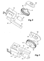
- the lock represented on the figure 1 comprises an electric motor 10 provided with an output shaft forming a worm 15, a gear wheel 20 meshing with the worm 15, and a bolt 30 slidably mounted, these various elements being arranged in a housing 40.
- the toothed wheel 20 is rotatably mounted about an axis 21 which extends perpendicular to the output shaft of the motor 10 so that the output shaft of the motor is coincident in the geometric plane of the wheel.
- the wheel 20 has a first face 22, facing a steering column, not shown, which is provided with a cam 23 in the disk portion which cooperates in thrust with the bolt.
- the bolt 30 has, in addition to a main bar 31, a lateral appendage 35 adapted to be interposed in the path of the cam 23 when it pivots with the toothed wheel 20 to move closer to an outer ring of the steering column.
- the bolt is advantageously biased in the locking position by a spring.
- This lateral appendix has an S shape whose upper curvature forms a bearing wall for the cam 23 of the toothed wheel and whose lower curvature receives within it a retaining element in the unlocked position as will be described later.
- the bolt 30 slidably travels in a plane parallel to the main plane of the toothed wheel.
- the gear wheel 20 being here oriented so that it lies in a plane parallel to the steering column, the bolt therefore circulates itself parallel to the main direction of the steering column.
- the steering column In order to be locked when the bolt is in the final position, the steering column has a lateral appendix cooperating with the bolt, here a ring gear 80 whose teeth have interstices between them receiving the bolt in its extended locking position.
- the lateral appendage may be a simple radially oriented finger relative to the main direction of the steering column, or a transverse plate provided with a series of through orifices and able to receive. the bolt in multiple angular positions of the steering column.
- the toothed wheel 20 has on its side facing away from the column a circular arc track 24 constituted here in the form of an extra thickness outside the face of the wheel 20.
- the track 24 extends over three quarters of the angular extent around the axis of the wheel 20 and has at each of its ends a sliding chamfer which joins the main plane of the face 22.
- the track 22 cooperates with a shuttle 60 mounted to slide transversely to the main plane of the wheel and more specifically here slidably mounted on the axis of rotation of the wheel.
- This shuttle has a radial extension 62 in the direction of the bolt 30 and comes, by a finger 64 oriented transversely to the main plane of the toothed wheel 20, extend inside the bolt 30 and selectively as will be explained below.
- the shuttle 60 is in fact bearing against the track 22 by means of a slider 65 formed in relief on the face of the shuttle facing the wheel and the shuttle is thus held in abutment against the track 22 transversely to the gear wheel 20 by a spring not shown.
- the shuttle thereby undergoes a displacement transverse to the toothed wheel as it pivots on itself when the slide 65 ascends or descends from the overthicked track 24.
- the shuttle 60 is held at the same time. against a pivoting about the axis of rotation of the toothed wheel by cooperation of a finger not shown from the casing of the lock and engaged in a through orifice of the shuttle 60.
- the overthicked track 24 is arranged in such a way that when the bolt is in the locking position of the column the shuttle is spaced apart from the toothed wheel, that is to say that the slide 65 bears on the runway 24 and the locking finger of the shuttle does not engage the bolt.
- the thickened track is arranged in such a way that the shuttle 60 is close to the gear wheel, that is to say that the slide 65 is off the track 24 when the bolt is in the unlocking position and that the shuttle then comes secure by the overlock finger the bolt in the unlocked position.
- the S-shaped formed by the bolt has its curvature proximal to the main body of the bolt vis-à-vis the overlock finger when the bolt is in the unlocked position, allowing the penetration of the overlock finger in the curvature proximal to the S.
- the finger is then positioned as an obstacle on the return path of the bolt and more specifically the proximal curvature of the S, thus preventing an inadvertent return of the bolt to its locking position.
- the extra thickness presented by the track 24 goes is increasing during the course of the track, so that a first end of the arc described by the track is close to a main plane of the wheel and another end of the arc described by the track 22 is further away laterally from the main plane of the wheel 20.
- the casing 50 of the antitheft is advantageously arranged in the form of a liquor basin, that is to say in extension in the main direction of the steering column is in a cross section in the form of a bean, that is to say between two transverse limits in an arc of radius of respectively lower and upper radius.
- the steering column antithe then marries a cylinder contour of the steering column to occupy only a small radial space in the column.
- Such bulk is particularly advantageous in the present case where the antitheft steering column is a constituent element of a motor assistance module to the rotation of the steering column.
- the fact of integrating the antitheft into a motorized assistance module to the pivoting of the steering column provides an advantage in terms of safety since the antitheft is then in a particularly low part of the column, at particularly great distance from the dashboard where a thief acts by predilection and in a particularly inaccessible part of the vehicle.
- the motor assistance module comprises an assistance motor 70 which is oriented so that its output shaft 75 extends parallel to the steering column.
- the output shaft 75 of the motor 70 has a peripheral toothing which meshes with a ring gear 80 surrounding the steering column in order to drive the latter in rotation.
- the ring gear 80 is advantageously the ring in which the bolt 30 engages so that a single ring gear is used for the two driving and locking functions, further reducing the space required for the implementation of the module. described assistance.
- the antitheft and the assistance motor 70 are arranged radially opposite to the steering column, so that the bolt 30 and the shaft so the assistance engine do not interfere.
- the motorized assistance module advantageously comprises the same electronic control unit of the assistance to pivoting and control of the blocking of the column, which ensures that no assistance command is applied to the assistance engine when the antitheft is in locked position.
- the common steering unit motorized assistance and the locking of the column is advantageously equipped with a control logic implementing a slight rotational movement of the steering column when it simultaneously controls a driving force in unlocking the bolt.
- a possible frictional retention is eliminated between the bolt and the steering column, for example between the bolt and a lateral edge of a tooth of the ring gear 80 and the bolt loosely circulates in a reliable manner. each time the vehicle is put into tension.
- the control unit is advantageously implemented in the form of an electronic circuit placed in a common housing 90 of the assistance engine 70 and the lock.
- the electronic circuit is advantageously positioned outside the casing 50 of the lock.
- this control unit takes into account the positioning of the bolt which is indicated by the receipt of output signals of positioning sensors of the bolt disposed in the lock.
- These two sensors, referenced 35 and 36 are here magnetic sensors activated by a magnet disposed on the bolt but which may alternatively be mechanical sensors activated by a boss of the bolt. Alternatively these may be sensors associated with the toothed wheel, the locking shuttle or any other body of the lock.
- the signals delivered by these sensors are advantageously directly read by the control unit.
Landscapes
- Engineering & Computer Science (AREA)
- Mechanical Engineering (AREA)
- Lock And Its Accessories (AREA)
Priority Applications (5)
| Application Number | Priority Date | Filing Date | Title |
|---|---|---|---|
| EP11150893.3A EP2476592B1 (de) | 2011-01-13 | 2011-01-13 | Diebstahlsicherung für Lenksäule eines Kraftfahrzeugs |
| CN201180069271.7A CN103492239A (zh) | 2011-01-13 | 2011-12-21 | 用于机动车辆的转向锁定装置 |
| PCT/EP2011/073549 WO2012095246A1 (fr) | 2011-01-13 | 2011-12-21 | Antivol de direction pour vehicule automobile |
| JP2013548769A JP2014505624A (ja) | 2011-01-13 | 2011-12-21 | 自動車のステアリングコラムロック装置 |
| US13/979,228 US9085274B2 (en) | 2011-01-13 | 2011-12-21 | Steering lock for a motor vehicle |
Applications Claiming Priority (1)
| Application Number | Priority Date | Filing Date | Title |
|---|---|---|---|
| EP11150893.3A EP2476592B1 (de) | 2011-01-13 | 2011-01-13 | Diebstahlsicherung für Lenksäule eines Kraftfahrzeugs |
Publications (2)
| Publication Number | Publication Date |
|---|---|
| EP2476592A1 true EP2476592A1 (de) | 2012-07-18 |
| EP2476592B1 EP2476592B1 (de) | 2020-04-08 |
Family
ID=44148655
Family Applications (1)
| Application Number | Title | Priority Date | Filing Date |
|---|---|---|---|
| EP11150893.3A Not-in-force EP2476592B1 (de) | 2011-01-13 | 2011-01-13 | Diebstahlsicherung für Lenksäule eines Kraftfahrzeugs |
Country Status (5)
| Country | Link |
|---|---|
| US (1) | US9085274B2 (de) |
| EP (1) | EP2476592B1 (de) |
| JP (1) | JP2014505624A (de) |
| CN (1) | CN103492239A (de) |
| WO (1) | WO2012095246A1 (de) |
Cited By (1)
| Publication number | Priority date | Publication date | Assignee | Title |
|---|---|---|---|---|
| US20150251632A1 (en) * | 2012-10-04 | 2015-09-10 | U-Shin Deutschland Zugangssysteme Gmbh | Electrical steering column lock for an automotive vehicle |
Families Citing this family (6)
| Publication number | Priority date | Publication date | Assignee | Title |
|---|---|---|---|---|
| US8424348B2 (en) * | 2010-01-27 | 2013-04-23 | Strattec Security Corporation | Steering lock |
| EP2479073B1 (de) * | 2011-01-21 | 2014-01-15 | VALEO Sicherheitssysteme GmbH | Diebstahlsicherung für Lenksäule eines Kraftfahrzeugs |
| TWI458882B (zh) * | 2012-05-15 | 2014-11-01 | Wfe Technology Corp | 電子鎖之作動馬達組 |
| DE102013217735A1 (de) * | 2012-09-07 | 2014-03-13 | Strattec Security Corporation | Lenkschloss |
| JP7240150B2 (ja) | 2017-11-27 | 2023-03-15 | Ntn株式会社 | 電動アクチュエータ |
| DE102020132224A1 (de) * | 2020-12-03 | 2022-06-09 | Eto Magnetic Gmbh | Schnellschaltende Aktorvorrichtung |
Citations (3)
| Publication number | Priority date | Publication date | Assignee | Title |
|---|---|---|---|---|
| US5454238A (en) * | 1994-07-25 | 1995-10-03 | General Motors Corporation | Anti-theft apparatus for motor vehicle steering column |
| EP0846603A1 (de) * | 1996-12-05 | 1998-06-10 | Valeo Securite Habitacle | Antrieb, insbesondere für eine elektrische Fahrzeugdiebstahlsicherung |
| FR2799709A1 (fr) * | 1999-10-19 | 2001-04-20 | Valeo Securite Habitacle | Antivol electrique de direction de vehicule automobile |
Family Cites Families (26)
| Publication number | Priority date | Publication date | Assignee | Title |
|---|---|---|---|---|
| FR2483867A1 (fr) * | 1980-06-06 | 1981-12-11 | Antivols Simplex Sa | Antivol de direction pour vehicule automobile |
| US5016454A (en) * | 1988-07-13 | 1991-05-21 | Al Sheikh Edward G | Motor vehicle supplementary locking mechanism |
| US5360254A (en) * | 1992-02-26 | 1994-11-01 | Honda Giken Kogyo Kabushiki Kaisha | Automobile with movable roof storable in trunk lid |
| GB9507810D0 (en) * | 1995-04-18 | 1995-05-31 | Marshall Wolverhampton | Automotive steering security arrangement |
| FR2756795B1 (fr) * | 1996-12-05 | 1999-01-22 | Valeo Securite Habitacle | Antivol a engrenage pour une colonne de direction de vehicule automobile |
| US6107694A (en) * | 1996-12-12 | 2000-08-22 | Mostrom; Lloyd C. | Baffler--Model A --an automobile anti-theft device |
| US6034442A (en) * | 1997-02-18 | 2000-03-07 | Mostrom; Lloyd C. | Frustrator--Model E |
| US5906120A (en) * | 1998-04-09 | 1999-05-25 | Ford Global Technologies, Inc. | Automotive vehicle steering column lock mechanism |
| FR2788479B1 (fr) * | 1999-01-15 | 2001-04-06 | Valeo Securite Habitacle | Dispositif d'antivol comportant un interrupteur electrique pour la detection de l'introduction d'une clef |
| JP3810327B2 (ja) * | 2002-02-27 | 2006-08-16 | 株式会社ジェイテクト | 操舵軸のロック装置 |
| DE10247802B3 (de) * | 2002-10-14 | 2004-02-05 | Huf Hülsbeck & Fürst Gmbh & Co. Kg | Vorrichtung zum Sperren der Lenkspindel eines Kraftfahrzeugs |
| US6748774B2 (en) * | 2002-10-15 | 2004-06-15 | Delphi Technologies, Inc. | Forward firing shaft lock mechanism |
| CN100448723C (zh) * | 2003-02-18 | 2009-01-07 | 富兰克林·费迪南德·尼德里希 | 用于通过车把操纵车辆的防盗装置 |
| DE10320138B3 (de) * | 2003-05-06 | 2005-01-13 | Huf Hülsbeck & Fürst Gmbh & Co. Kg | Vorrichtung zum Sperren der Lenkspindel eines Kraftfahrzeugs |
| US7062944B2 (en) * | 2003-11-26 | 2006-06-20 | Delphi Technologies, Inc. | Dual taper steering column lock bolt |
| US20050120761A1 (en) * | 2003-12-03 | 2005-06-09 | Rouleau James E. | Column assembly of a vehicle having a steering column to be locked and unlocked |
| JP2006131043A (ja) * | 2004-11-04 | 2006-05-25 | Tokai Rika Co Ltd | ステアリングロック装置 |
| DE102004053438A1 (de) * | 2004-11-05 | 2006-05-11 | Valeo Sicherheitssysteme Gmbh | Lenkschloß |
| JP4624912B2 (ja) * | 2005-11-30 | 2011-02-02 | 株式会社アルファ | 電動ステアリングロック装置 |
| DE102007034476B4 (de) * | 2007-07-20 | 2009-05-20 | Zf Friedrichshafen Ag | Vorrichtung zur Diebstahlsicherung eines Kraftfahrzeuges |
| US7596976B2 (en) * | 2007-11-30 | 2009-10-06 | Alpha Corporation | Electric steering lock device |
| WO2009100620A1 (zh) * | 2008-02-14 | 2009-08-20 | Jian-Jhong Fong | 车辆方向盘锁死防盗装置 |
| JP2010006112A (ja) * | 2008-06-24 | 2010-01-14 | Tokai Rika Co Ltd | ステアリングロック装置 |
| JP5229551B2 (ja) * | 2008-08-29 | 2013-07-03 | 株式会社ジェイテクト | 車両用操舵装置 |
| JP5260358B2 (ja) * | 2009-03-06 | 2013-08-14 | 株式会社ユーシン | 電動ステアリングロック装置 |
| JP5887711B2 (ja) * | 2010-11-16 | 2016-03-16 | 株式会社ジェイテクト | ロック装置及び電動パワーステアリング装置 |
-
2011
- 2011-01-13 EP EP11150893.3A patent/EP2476592B1/de not_active Not-in-force
- 2011-12-21 US US13/979,228 patent/US9085274B2/en active Active
- 2011-12-21 JP JP2013548769A patent/JP2014505624A/ja active Pending
- 2011-12-21 CN CN201180069271.7A patent/CN103492239A/zh active Pending
- 2011-12-21 WO PCT/EP2011/073549 patent/WO2012095246A1/fr not_active Ceased
Patent Citations (3)
| Publication number | Priority date | Publication date | Assignee | Title |
|---|---|---|---|---|
| US5454238A (en) * | 1994-07-25 | 1995-10-03 | General Motors Corporation | Anti-theft apparatus for motor vehicle steering column |
| EP0846603A1 (de) * | 1996-12-05 | 1998-06-10 | Valeo Securite Habitacle | Antrieb, insbesondere für eine elektrische Fahrzeugdiebstahlsicherung |
| FR2799709A1 (fr) * | 1999-10-19 | 2001-04-20 | Valeo Securite Habitacle | Antivol electrique de direction de vehicule automobile |
Cited By (4)
| Publication number | Priority date | Publication date | Assignee | Title |
|---|---|---|---|---|
| US20150251632A1 (en) * | 2012-10-04 | 2015-09-10 | U-Shin Deutschland Zugangssysteme Gmbh | Electrical steering column lock for an automotive vehicle |
| US20150266449A1 (en) * | 2012-10-04 | 2015-09-24 | U-Shin Deutschland Zugangssysteme Gmbh | Electrical steering column lock for an automotive vehicle |
| US10017152B2 (en) * | 2012-10-04 | 2018-07-10 | U-Shin Deutschland Zugangssyteme GmbH | Electrical steering column lock for an automotive vehicle |
| US10112578B2 (en) * | 2012-10-04 | 2018-10-30 | U-Shin Deutschland Zugangssysteme Gmbh | Electrical steering column lock for an automotive vehicle |
Also Published As
| Publication number | Publication date |
|---|---|
| CN103492239A (zh) | 2014-01-01 |
| JP2014505624A (ja) | 2014-03-06 |
| US20140069155A1 (en) | 2014-03-13 |
| WO2012095246A1 (fr) | 2012-07-19 |
| US9085274B2 (en) | 2015-07-21 |
| EP2476592B1 (de) | 2020-04-08 |
Similar Documents
| Publication | Publication Date | Title |
|---|---|---|
| EP2476592B1 (de) | Diebstahlsicherung für Lenksäule eines Kraftfahrzeugs | |
| EP2479073B1 (de) | Diebstahlsicherung für Lenksäule eines Kraftfahrzeugs | |
| FR3060630B1 (fr) | Commande d'ouverture affleurante a ejection et retraction mecanique ou electrique. | |
| FR2706846A1 (de) | ||
| FR2979881A1 (fr) | Colonne de direction comprenant un mecanisme de blocage en profondeur ameliore. | |
| FR3029489A1 (fr) | Mecanisme de colonne de direction ajustable en profondeur a butee escamotable | |
| FR2632585A1 (fr) | Retroviseur exterieur pour vehicules automobiles | |
| FR2777523A1 (fr) | Antivol de colonne de direction comportant des moyens perfectionnes de blocage du pene | |
| EP3041715B1 (de) | Diebstahlschutzvorrichtung für die lenksäule eines kraftfahrzeugs | |
| FR2739072A1 (fr) | Antivol motorise de direction de vehicule automobile | |
| EP1477378B1 (de) | Elektrisches Schloss einer Lenkspindel eines Kraftfahrzeuges | |
| FR2523532A1 (fr) | Dispositif antivol pour un arbre tournant, notamment pour la colonne de direction d'un vehicule automobile | |
| FR2678314A1 (fr) | Dispositif d'assistance a la fermeture pour portiere de vehicule automobile. | |
| FR3142156A1 (fr) | Dispositif de direction de véhicule comprenant une structure mobile et un dispositif de verrouillage de la structure mobile | |
| EP0846603B1 (de) | Antrieb, insbesondere für eine elektrische Fahrzeugdiebstahlsicherung | |
| FR2766441A1 (fr) | Antivol electrique comportant des moyens complementaires de blocage du pene | |
| EP2736773B1 (de) | Antidiebstahlvorrichtung für eine lenksäule eines kraftfahrzeuges | |
| FR2474573A1 (fr) | Dispositif d'actionnement electrique pour un organe de manoeuvre de serrures et objets analogues | |
| FR2889142A1 (fr) | Dispositif antivol permettant de commander le verrouillage d'une colonne de direction d'un vehicule automobile | |
| EP2072353B1 (de) | Lenkradschloss für Lenksäule | |
| EP2460171B1 (de) | Anpassbarer zündschalter | |
| WO2004028870A1 (fr) | Dispositif antivol pour vehicule automobile avec direction assistee hydraulique | |
| FR2873075A1 (fr) | Verrou electrique decale d'un arbre de direction de vehicule automobile | |
| FR2805560A1 (fr) | Module de serrure electrique pour une porte d'un vehicule | |
| WO2014202548A1 (fr) | Antivol de colonne de direction et vehicule automobile |
Legal Events
| Date | Code | Title | Description |
|---|---|---|---|
| PUAI | Public reference made under article 153(3) epc to a published international application that has entered the european phase |
Free format text: ORIGINAL CODE: 0009012 |
|
| AK | Designated contracting states |
Kind code of ref document: A1 Designated state(s): AL AT BE BG CH CY CZ DE DK EE ES FI FR GB GR HR HU IE IS IT LI LT LU LV MC MK MT NL NO PL PT RO RS SE SI SK SM TR |
|
| AX | Request for extension of the european patent |
Extension state: BA ME |
|
| 17P | Request for examination filed |
Effective date: 20130117 |
|
| RAP1 | Party data changed (applicant data changed or rights of an application transferred) |
Owner name: U-SHIN DEUTSCHLAND ZUGANGSSYSTEME GMBH |
|
| STAA | Information on the status of an ep patent application or granted ep patent |
Free format text: STATUS: EXAMINATION IS IN PROGRESS |
|
| 17Q | First examination report despatched |
Effective date: 20170201 |
|
| GRAP | Despatch of communication of intention to grant a patent |
Free format text: ORIGINAL CODE: EPIDOSNIGR1 |
|
| STAA | Information on the status of an ep patent application or granted ep patent |
Free format text: STATUS: GRANT OF PATENT IS INTENDED |
|
| INTG | Intention to grant announced |
Effective date: 20200103 |
|
| GRAS | Grant fee paid |
Free format text: ORIGINAL CODE: EPIDOSNIGR3 |
|
| GRAA | (expected) grant |
Free format text: ORIGINAL CODE: 0009210 |
|
| STAA | Information on the status of an ep patent application or granted ep patent |
Free format text: STATUS: THE PATENT HAS BEEN GRANTED |
|
| AK | Designated contracting states |
Kind code of ref document: B1 Designated state(s): AL AT BE BG CH CY CZ DE DK EE ES FI FR GB GR HR HU IE IS IT LI LT LU LV MC MK MT NL NO PL PT RO RS SE SI SK SM TR |
|
| REG | Reference to a national code |
Ref country code: GB Ref legal event code: FG4D Free format text: NOT ENGLISH |
|
| REG | Reference to a national code |
Ref country code: AT Ref legal event code: REF Ref document number: 1253966 Country of ref document: AT Kind code of ref document: T Effective date: 20200415 Ref country code: CH Ref legal event code: EP |
|
| REG | Reference to a national code |
Ref country code: IE Ref legal event code: FG4D Free format text: LANGUAGE OF EP DOCUMENT: FRENCH |
|
| REG | Reference to a national code |
Ref country code: DE Ref legal event code: R096 Ref document number: 602011066082 Country of ref document: DE |
|
| REG | Reference to a national code |
Ref country code: NL Ref legal event code: MP Effective date: 20200408 |
|
| REG | Reference to a national code |
Ref country code: LT Ref legal event code: MG4D |
|
| PG25 | Lapsed in a contracting state [announced via postgrant information from national office to epo] |
Ref country code: FI Free format text: LAPSE BECAUSE OF FAILURE TO SUBMIT A TRANSLATION OF THE DESCRIPTION OR TO PAY THE FEE WITHIN THE PRESCRIBED TIME-LIMIT Effective date: 20200408 Ref country code: IS Free format text: LAPSE BECAUSE OF FAILURE TO SUBMIT A TRANSLATION OF THE DESCRIPTION OR TO PAY THE FEE WITHIN THE PRESCRIBED TIME-LIMIT Effective date: 20200808 Ref country code: NL Free format text: LAPSE BECAUSE OF FAILURE TO SUBMIT A TRANSLATION OF THE DESCRIPTION OR TO PAY THE FEE WITHIN THE PRESCRIBED TIME-LIMIT Effective date: 20200408 Ref country code: PT Free format text: LAPSE BECAUSE OF FAILURE TO SUBMIT A TRANSLATION OF THE DESCRIPTION OR TO PAY THE FEE WITHIN THE PRESCRIBED TIME-LIMIT Effective date: 20200817 Ref country code: NO Free format text: LAPSE BECAUSE OF FAILURE TO SUBMIT A TRANSLATION OF THE DESCRIPTION OR TO PAY THE FEE WITHIN THE PRESCRIBED TIME-LIMIT Effective date: 20200708 Ref country code: SE Free format text: LAPSE BECAUSE OF FAILURE TO SUBMIT A TRANSLATION OF THE DESCRIPTION OR TO PAY THE FEE WITHIN THE PRESCRIBED TIME-LIMIT Effective date: 20200408 Ref country code: GR Free format text: LAPSE BECAUSE OF FAILURE TO SUBMIT A TRANSLATION OF THE DESCRIPTION OR TO PAY THE FEE WITHIN THE PRESCRIBED TIME-LIMIT Effective date: 20200709 Ref country code: LT Free format text: LAPSE BECAUSE OF FAILURE TO SUBMIT A TRANSLATION OF THE DESCRIPTION OR TO PAY THE FEE WITHIN THE PRESCRIBED TIME-LIMIT Effective date: 20200408 |
|
| REG | Reference to a national code |
Ref country code: AT Ref legal event code: MK05 Ref document number: 1253966 Country of ref document: AT Kind code of ref document: T Effective date: 20200408 |
|
| PG25 | Lapsed in a contracting state [announced via postgrant information from national office to epo] |
Ref country code: RS Free format text: LAPSE BECAUSE OF FAILURE TO SUBMIT A TRANSLATION OF THE DESCRIPTION OR TO PAY THE FEE WITHIN THE PRESCRIBED TIME-LIMIT Effective date: 20200408 Ref country code: BG Free format text: LAPSE BECAUSE OF FAILURE TO SUBMIT A TRANSLATION OF THE DESCRIPTION OR TO PAY THE FEE WITHIN THE PRESCRIBED TIME-LIMIT Effective date: 20200708 Ref country code: LV Free format text: LAPSE BECAUSE OF FAILURE TO SUBMIT A TRANSLATION OF THE DESCRIPTION OR TO PAY THE FEE WITHIN THE PRESCRIBED TIME-LIMIT Effective date: 20200408 Ref country code: HR Free format text: LAPSE BECAUSE OF FAILURE TO SUBMIT A TRANSLATION OF THE DESCRIPTION OR TO PAY THE FEE WITHIN THE PRESCRIBED TIME-LIMIT Effective date: 20200408 |
|
| PG25 | Lapsed in a contracting state [announced via postgrant information from national office to epo] |
Ref country code: AL Free format text: LAPSE BECAUSE OF FAILURE TO SUBMIT A TRANSLATION OF THE DESCRIPTION OR TO PAY THE FEE WITHIN THE PRESCRIBED TIME-LIMIT Effective date: 20200408 |
|
| REG | Reference to a national code |
Ref country code: DE Ref legal event code: R097 Ref document number: 602011066082 Country of ref document: DE |
|
| PG25 | Lapsed in a contracting state [announced via postgrant information from national office to epo] |
Ref country code: IT Free format text: LAPSE BECAUSE OF FAILURE TO SUBMIT A TRANSLATION OF THE DESCRIPTION OR TO PAY THE FEE WITHIN THE PRESCRIBED TIME-LIMIT Effective date: 20200408 Ref country code: SM Free format text: LAPSE BECAUSE OF FAILURE TO SUBMIT A TRANSLATION OF THE DESCRIPTION OR TO PAY THE FEE WITHIN THE PRESCRIBED TIME-LIMIT Effective date: 20200408 Ref country code: AT Free format text: LAPSE BECAUSE OF FAILURE TO SUBMIT A TRANSLATION OF THE DESCRIPTION OR TO PAY THE FEE WITHIN THE PRESCRIBED TIME-LIMIT Effective date: 20200408 Ref country code: DK Free format text: LAPSE BECAUSE OF FAILURE TO SUBMIT A TRANSLATION OF THE DESCRIPTION OR TO PAY THE FEE WITHIN THE PRESCRIBED TIME-LIMIT Effective date: 20200408 Ref country code: EE Free format text: LAPSE BECAUSE OF FAILURE TO SUBMIT A TRANSLATION OF THE DESCRIPTION OR TO PAY THE FEE WITHIN THE PRESCRIBED TIME-LIMIT Effective date: 20200408 Ref country code: ES Free format text: LAPSE BECAUSE OF FAILURE TO SUBMIT A TRANSLATION OF THE DESCRIPTION OR TO PAY THE FEE WITHIN THE PRESCRIBED TIME-LIMIT Effective date: 20200408 Ref country code: RO Free format text: LAPSE BECAUSE OF FAILURE TO SUBMIT A TRANSLATION OF THE DESCRIPTION OR TO PAY THE FEE WITHIN THE PRESCRIBED TIME-LIMIT Effective date: 20200408 Ref country code: CZ Free format text: LAPSE BECAUSE OF FAILURE TO SUBMIT A TRANSLATION OF THE DESCRIPTION OR TO PAY THE FEE WITHIN THE PRESCRIBED TIME-LIMIT Effective date: 20200408 |
|
| PLBE | No opposition filed within time limit |
Free format text: ORIGINAL CODE: 0009261 |
|
| STAA | Information on the status of an ep patent application or granted ep patent |
Free format text: STATUS: NO OPPOSITION FILED WITHIN TIME LIMIT |
|
| PG25 | Lapsed in a contracting state [announced via postgrant information from national office to epo] |
Ref country code: PL Free format text: LAPSE BECAUSE OF FAILURE TO SUBMIT A TRANSLATION OF THE DESCRIPTION OR TO PAY THE FEE WITHIN THE PRESCRIBED TIME-LIMIT Effective date: 20200408 Ref country code: SK Free format text: LAPSE BECAUSE OF FAILURE TO SUBMIT A TRANSLATION OF THE DESCRIPTION OR TO PAY THE FEE WITHIN THE PRESCRIBED TIME-LIMIT Effective date: 20200408 |
|
| 26N | No opposition filed |
Effective date: 20210112 |
|
| PG25 | Lapsed in a contracting state [announced via postgrant information from national office to epo] |
Ref country code: SI Free format text: LAPSE BECAUSE OF FAILURE TO SUBMIT A TRANSLATION OF THE DESCRIPTION OR TO PAY THE FEE WITHIN THE PRESCRIBED TIME-LIMIT Effective date: 20200408 |
|
| PG25 | Lapsed in a contracting state [announced via postgrant information from national office to epo] |
Ref country code: MC Free format text: LAPSE BECAUSE OF FAILURE TO SUBMIT A TRANSLATION OF THE DESCRIPTION OR TO PAY THE FEE WITHIN THE PRESCRIBED TIME-LIMIT Effective date: 20200408 |
|
| REG | Reference to a national code |
Ref country code: CH Ref legal event code: PL |
|
| GBPC | Gb: european patent ceased through non-payment of renewal fee |
Effective date: 20210113 |
|
| PG25 | Lapsed in a contracting state [announced via postgrant information from national office to epo] |
Ref country code: LU Free format text: LAPSE BECAUSE OF NON-PAYMENT OF DUE FEES Effective date: 20210113 |
|
| REG | Reference to a national code |
Ref country code: BE Ref legal event code: MM Effective date: 20210131 |
|
| PG25 | Lapsed in a contracting state [announced via postgrant information from national office to epo] |
Ref country code: GB Free format text: LAPSE BECAUSE OF NON-PAYMENT OF DUE FEES Effective date: 20210113 Ref country code: CH Free format text: LAPSE BECAUSE OF NON-PAYMENT OF DUE FEES Effective date: 20210131 Ref country code: LI Free format text: LAPSE BECAUSE OF NON-PAYMENT OF DUE FEES Effective date: 20210131 |
|
| PG25 | Lapsed in a contracting state [announced via postgrant information from national office to epo] |
Ref country code: IE Free format text: LAPSE BECAUSE OF NON-PAYMENT OF DUE FEES Effective date: 20210113 |
|
| PG25 | Lapsed in a contracting state [announced via postgrant information from national office to epo] |
Ref country code: BE Free format text: LAPSE BECAUSE OF NON-PAYMENT OF DUE FEES Effective date: 20210131 |
|
| PGFP | Annual fee paid to national office [announced via postgrant information from national office to epo] |
Ref country code: FR Payment date: 20230125 Year of fee payment: 13 |
|
| PG25 | Lapsed in a contracting state [announced via postgrant information from national office to epo] |
Ref country code: HU Free format text: LAPSE BECAUSE OF FAILURE TO SUBMIT A TRANSLATION OF THE DESCRIPTION OR TO PAY THE FEE WITHIN THE PRESCRIBED TIME-LIMIT; INVALID AB INITIO Effective date: 20110113 Ref country code: CY Free format text: LAPSE BECAUSE OF FAILURE TO SUBMIT A TRANSLATION OF THE DESCRIPTION OR TO PAY THE FEE WITHIN THE PRESCRIBED TIME-LIMIT Effective date: 20200408 |
|
| PGFP | Annual fee paid to national office [announced via postgrant information from national office to epo] |
Ref country code: DE Payment date: 20230112 Year of fee payment: 13 |
|
| PG25 | Lapsed in a contracting state [announced via postgrant information from national office to epo] |
Ref country code: MK Free format text: LAPSE BECAUSE OF FAILURE TO SUBMIT A TRANSLATION OF THE DESCRIPTION OR TO PAY THE FEE WITHIN THE PRESCRIBED TIME-LIMIT Effective date: 20200408 |
|
| PG25 | Lapsed in a contracting state [announced via postgrant information from national office to epo] |
Ref country code: TR Free format text: LAPSE BECAUSE OF FAILURE TO SUBMIT A TRANSLATION OF THE DESCRIPTION OR TO PAY THE FEE WITHIN THE PRESCRIBED TIME-LIMIT Effective date: 20200408 |
|
| REG | Reference to a national code |
Ref country code: DE Ref legal event code: R119 Ref document number: 602011066082 Country of ref document: DE |
|
| PG25 | Lapsed in a contracting state [announced via postgrant information from national office to epo] |
Ref country code: MT Free format text: LAPSE BECAUSE OF FAILURE TO SUBMIT A TRANSLATION OF THE DESCRIPTION OR TO PAY THE FEE WITHIN THE PRESCRIBED TIME-LIMIT Effective date: 20200408 |
|
| PG25 | Lapsed in a contracting state [announced via postgrant information from national office to epo] |
Ref country code: DE Free format text: LAPSE BECAUSE OF NON-PAYMENT OF DUE FEES Effective date: 20240801 |
|
| PG25 | Lapsed in a contracting state [announced via postgrant information from national office to epo] |
Ref country code: FR Free format text: LAPSE BECAUSE OF NON-PAYMENT OF DUE FEES Effective date: 20240131 |
|
| PG25 | Lapsed in a contracting state [announced via postgrant information from national office to epo] |
Ref country code: FR Free format text: LAPSE BECAUSE OF NON-PAYMENT OF DUE FEES Effective date: 20240131 Ref country code: DE Free format text: LAPSE BECAUSE OF NON-PAYMENT OF DUE FEES Effective date: 20240801 |