EP0846648A1 - Kollisionsvermeidungsvorrichtung eines Krans - Google Patents
Kollisionsvermeidungsvorrichtung eines Krans Download PDFInfo
- Publication number
- EP0846648A1 EP0846648A1 EP97309771A EP97309771A EP0846648A1 EP 0846648 A1 EP0846648 A1 EP 0846648A1 EP 97309771 A EP97309771 A EP 97309771A EP 97309771 A EP97309771 A EP 97309771A EP 0846648 A1 EP0846648 A1 EP 0846648A1
- Authority
- EP
- European Patent Office
- Prior art keywords
- lowering
- swing
- hoisting
- hoisting accessory
- amount
- Prior art date
- Legal status (The legal status is an assumption and is not a legal conclusion. Google has not performed a legal analysis and makes no representation as to the accuracy of the status listed.)
- Granted
Links
Images



Classifications
-
- B—PERFORMING OPERATIONS; TRANSPORTING
- B66—HOISTING; LIFTING; HAULING
- B66C—CRANES; LOAD-ENGAGING ELEMENTS OR DEVICES FOR CRANES, CAPSTANS, WINCHES, OR TACKLES
- B66C13/00—Other constructional features or details
- B66C13/18—Control systems or devices
- B66C13/48—Automatic control of crane drives for producing a single or repeated working cycle; Program control
-
- B—PERFORMING OPERATIONS; TRANSPORTING
- B66—HOISTING; LIFTING; HAULING
- B66C—CRANES; LOAD-ENGAGING ELEMENTS OR DEVICES FOR CRANES, CAPSTANS, WINCHES, OR TACKLES
- B66C13/00—Other constructional features or details
- B66C13/04—Auxiliary devices for controlling movements of suspended loads, or preventing cable slack
- B66C13/06—Auxiliary devices for controlling movements of suspended loads, or preventing cable slack for minimising or preventing longitudinal or transverse swinging of loads
- B66C13/063—Auxiliary devices for controlling movements of suspended loads, or preventing cable slack for minimising or preventing longitudinal or transverse swinging of loads electrical
-
- B—PERFORMING OPERATIONS; TRANSPORTING
- B66—HOISTING; LIFTING; HAULING
- B66C—CRANES; LOAD-ENGAGING ELEMENTS OR DEVICES FOR CRANES, CAPSTANS, WINCHES, OR TACKLES
- B66C13/00—Other constructional features or details
- B66C13/18—Control systems or devices
- B66C13/46—Position indicators for suspended loads or for crane elements
Definitions
- This invention relates to a lowering collision avoidance device of a crane. More particularly, the invention concerns the device useful when applied to a container handling crane installed in a container yard such as a port yard.
- a container yard such as a port yard
- containers transported there by a chassis, an automated guided vehicle (AGV) or the like are handled, one by one, by a container handling crane installed in the container yard so as to be stacked in layers (on other containers) or placed on the floor (lowered onto the ground) in the container yard.
- AGV automated guided vehicle
- Fig. 6 is an explanation drawing showing the constitution of a conventional container handling crane.
- the container handling crane has a structure comprising a girder 1 provided horizontally above a container yard, legs 2 supporting the girder 1, and running systems 3 provided at the lower ends of the legs 2, as well as a trolley 4 mounted on the girder and running along the girder 1, a hoisting/lowering device 5 mounted on the trolley 4, a hoisting/lowering drive motor 7 for driving the hoisting/lowering device 5, a rope 6 taken up or paid out by the hoisting/lowering device 5, a hoisting accessory 10 suspended from the hoisting/lowering device 5 via the rope 6, and a rope winding speed controller 20 for controlling the hoisting/lowering drive motor 7.
- the container handling crane acts as follows:
- the hoisting/lowering device 5 is driven by the hoisting/lowering drive motor 7 to pay out the rope 6, Thereby placing the hoisting accessory 10 on the container 11.
- the container 11 is held by a twist lock mechanism (not shown), and the rope 6 is taken up by the hoisting/lowering device 5 to lift (hoist) the container 11 together with the hoisting accessory 10.
- the trolley 4 After or simultaneously with hoisting the container 11, the trolley 4 is moved along the girder 4. After or simultaneously with moving the trolley 4, the rope 6 is paid out by the hoisting/lowering device 5 to move down (lower) the container 11 along with the hoisting accessory 10 and bring it to the target position 12.
- the container 11 when the container 11 is to be carried to the target position 12, the container 11 is hoisted once to a higher position in order to escape a stack of containers lying in the way. During or after this hoisting, the trolley 4 is moved to a targeted position above the container 21. While or after moving the trolley 4, the container 11 is lowered to be put to the target position 12.
- the container 11 is suspended by the rope 6, and so moves while swinging horizontally under the influence of the wind or changes in the speed of the trolley 4.
- various ideas have been incorporated, such as the provision of an auxiliary rope or the use of a method for automatically controlling the acceleration of the trolley 4.
- the present invention is set against the background of the above-described earlier technologies. Its object is to provide a lowering collision avoidance device of a crane which can rapidly lower a carried article (e.g., a container) to a place, where there are obstacles such as carried articles stacked adjacently in layers, while preventing the collision of the article with these obstacles.
- a carried article e.g., a container
- Certain preferred embodiments of the present invention are based on the fact that a container suspended by a rope vibrates with a long period like a pendulum and cannot cause abrupt changes in position owing to its inertia.
- a lowering collision avoidance device of a crane comprising a hoisting/lowering drive motor, a hoisting/lowering device driven by the hoisting/lowering drive motor, a rope taken up or paid out by the hoisting/lowering device, and a hoisting accessory suspended from the hoisting/lowering device via the rope and hoisted or lowered by the hoisting/lowering device, the crane lowering a carried article held by the hoisting accessory, together with the hoisting accessory, to a target position in a stack of other carried articles or to a floor position, the lowering collision avoidance device being adapted to prevent the collision of the carried article during lowering with obstacles such as the other carried articles stacked in layers adjacent to the target position,
- the lowering collision avoidance device comprising:
- the lowering collision avoidance device of a crane is similar to that of the first aspect of the invention except that
- the lowering collision avoidance device of a crane in accordance with the first aspect controls the lowering speed based on the results of comparison between the amount of swing of the hoisting accessory and a threshold level or a plurality of threshold levels, the direction of changes in the amount of swing of the hoisting accessory, and the lowering speed.
- a carried article is lowered, together with the hoisting accessory, to be placed in a stack of layers or on the floor at a site where there are obstacles such as carried articles stacked adjacently in layers.
- the lowering speed need not be decreased.
- maximum continued operation can be carried out to the extent that the carried article will not collide with the adjacent obstacle. In case a real risk of collision exists, the lowering of the carried article can be stopped.
- FIG. 1 is an explanation drawing showing the constitution of a container handling crane equipped with a lowering collision avoidance device in accordance with an embodiment of the present invention.
- Fig. 2 is a block diagram of a control system in the container handling crane shown in Fig. 1.
- a container handling crane has a structure comprising a girder 1, legs 2 and running systems 3, a trolley 4, a hoisting/lowering device 5, a hoisting/lowering drive motor 7, a rope 6, a hoisting accessory 10, and a rope winding speed controller 20.
- the hoisting accessory 10 is provided with a swing detection target 16 comprising a marking plate, an LED or a laser light source.
- the trolley 4 is equipped with a hoisting accessory swing detector 15 such as a CCD camera or a PSD camera.
- the hoisting/lowering device 5 is provided with a rope length detector 17 and a rope winding speed detector 18 which are usually installed.
- the rope length detector 17 detects the length of the rope 6, while the rope winding speed detector 18 detects the winding speed (i.e., the hoisting or lowering speed) of the rope 6.
- a detection signal from the hoisting accessory swing detector 15, a detection signal from the rope length detector 17, and a detection signal from the rope winding speed detector 18 are entered in an arithmetic unit 19. Based on these detection signals, the arithmetic unit 19 computes a command value for the lowering speed of the hoisting accessory 10 (i.e. the container) and issues it to the rope winding speed controller 20. The details of this action will be offered later on.
- the rope winding speed controller 20 controls the hoisting/lowering drive motor 7 to control the lowering speed of the hoisting accessory 10.
- this control system performs control in the following manner:
- the remaining lowering distance (L in Fig. 1) is always monitored so that if the lowering speed is decreased at a predetermined deceleration, the lowering can be stopped before intrusion into a canyon.
- the remaining lowering distance is determined in the following manner: On the girder 1, a rangefinder (not shown) is mounted so as to be positioned directly above each stack of the containers. These rangefinders detect the distance from the girder 1 to the top of each stack of containers. The altitudinal position of the container being carried, on the other hand, is detected by the rope length detector 17. The height of one container is already known. Thus, the remaining lowering distance is calculated from detection signals for both detections.
- a threshold level D 3 is set, and maximum displacement by the current swing is predicted from computations based on the current amount of swing (i.e., the amount of displacement from a predetermined position) detected by the hoisting accessory swing detector 15, the positional change rate computed from this amount of swing, and the period of vibration of the hoisting accessory computed from the current rope length detected by the rope length detector 17. If the predicted maximum displacement by swing is more than the threshold level D 3 , the lowering speed is decreased.
- FIG. 3 is a flow chart showing the actions of a lowering collision avoidance device in accordance with an embodiment of the invention.
- the respective parts are assigned the symbols S1 to S20.
- Fig. 4 is an explanation drawing, as viewed from above the container, of different types of operation according to the amount of swing and the direction of changes in the amount of swing in a threshold level-based control of a lowering collision avoidance device in accordance with an embodiment of the invention.
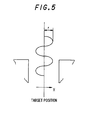
- Fig. 5 is an explanation drawing on a positional prediction-based control of a lowering collision avoidance device in accordance with an embodiment of the invention.
- the lowering of the hoisting accessory i.e. container
- the amount of swing, D is detected (S2, S3).
- the change rate of the amount of swing D is computed (S4), and comparisons between the detected amount of swing D and the threshold level D 1 or D 2 , and the change rate of the amount of swing D are considered as follows:
- Positional prediction means predicting maximum displacement by swing in the current status. In other words, if the current swing continues, the hoisting accessory moves downward in the range of the maximum displacement predicted.
- a threshold level D 3 e.g., ⁇ 110 mm
- the movement of the hoisting accessory is assumed as a simple harmonic motion.
- the amplitude of the hoisting accessory can be calculated from the position of the hoisting accessory (the amount of displacement from the predetermined position), the positional change rate, and the period of vibration as mentioned previously.
- the position of the hoisting accessory can be calculated using the detected values, while the positional change rate can be calculated from the detected values of position at each moment.
- the period of vibration can be calculated from the detected values of the rope length.
- the displacement of the hoisting accessory is represented by the equation 1 ⁇ where X 0 denotes the coordinates of the target position.
- X X 0 + r sin ⁇ t 1
- the displacement X R or X L is a composite vibration comprising a parallel swing and a skew swing, and thus, is not considered to be a simple harmonic motion.
- X R and X L are each reformed into the following equation for reduction into a parallel swing and a skew swing which are considered simple harmonic motions.
- X 1 X R +X L 2 :
- Parallel swing X2 X R - X L 2 : Skew swing
- the displacements X 1 and X 2 can be determined by the method described in (1) above.
- the periods of parallel swing and skew swing are different from each other.
- the functional forms of the original displacements X R and X L can be calculated from X 1 and X 2 by the above-described method.
- X R X 1 + X 2
- X L X 1 - X 2
- E R Max ⁇ X R ⁇
- the calculations for the logics of A and B above are made continuously at each scanning time point from the time when the bottom surface or the suspended container comes to a predetermined height above the entrance of the canyon, for example, 4 m above, or from the time when the trolley comes to a predetermined horizontal position apart from the entrance of the canyon, for example, within 1 meter, to the time when the container arrives at the floor (or is placed on the stack of containers in layers).
- the calculations are made at each scanning time point using the detected values of the rope length.
- the lowering collision avoidance device in accordance with the instant embodiment on a container handling crane, therefore, even if the current swing of the hoisting accessory 10 (i.e., the swing of the container 11) is marked, the lowering speed need not be decreased, when the swing decreases during the lowering of the container 11. Moreover, continued operation can be carried out to the extent that the container 11 will not collide with the adjacent containers 22 and 23. In case a real risk of collision exists, the lowering can be stopped. Thus, the cycle time can be shortened safely.
- a lowering collision avoidance device embodying the present invention is installed on a commercial machine for practical use, and is operated satisfactorily. Thus, its effectiveness has been demonstrated.
- the lowering collision avoidance device in accordance with a first aspect of the invention skillfully utilizes the facts that a carried article, such as a container, suspended by a rope vibrates with a long period like a pendulum and cannot cause abrupt changes in position owing to its inertia.
- the device controls the lowering speed based on the results of comparison between the amount of swing of the hoisting accessory and a threshold level or a plurality of threshold levels, the direction of changes in the amount of swing of the hoisting accessory, and the lowering speed.
- a carried article is lowered, together with the hoisting accessory, to be placed on a stack of containers in layers or on the floor at a site where there are obstacles such as carried articles stacked adjacently in layers.
- the swing of the hoisting accessory decreases during the lowering of the carried article even if the current swing of the hoisting accessory (i.e., the current swing of the carried article) is marked, the lowering speed need not be reduced.
- maximum continued operation can be carried out to the extent that the carried article will not collide with the adjacent obstacle. In case a real risk of collision exists, the lowering of the carried article can be stopped. This enables the cycle time to be shortened safely.
- a lowering collision avoidance device in accordance with a second aspect of the invention, maximum displacement by the swing of the hoisting accessory is predicted. Based on the results of comparison between the predicted maximum displacement by swing and a predetermined threshold level, the lowering speed is controlled. Thus, collision between the lowered carried article and the adjacent obstacle can be prevented more reliably.
Landscapes
- Engineering & Computer Science (AREA)
- Mechanical Engineering (AREA)
- Automation & Control Theory (AREA)
- Control And Safety Of Cranes (AREA)
Applications Claiming Priority (3)
| Application Number | Priority Date | Filing Date | Title |
|---|---|---|---|
| JP326575/96 | 1996-12-06 | ||
| JP32657596 | 1996-12-06 | ||
| JP32657596A JP3150636B2 (ja) | 1996-12-06 | 1996-12-06 | クレーンの巻き下げ衝突防止装置 |
Publications (2)
| Publication Number | Publication Date |
|---|---|
| EP0846648A1 true EP0846648A1 (de) | 1998-06-10 |
| EP0846648B1 EP0846648B1 (de) | 2002-07-24 |
Family
ID=18189348
Family Applications (1)
| Application Number | Title | Priority Date | Filing Date |
|---|---|---|---|
| EP97309771A Expired - Lifetime EP0846648B1 (de) | 1996-12-06 | 1997-12-04 | Einrichtung für die Kontrolle der Senkung einer Last in einem Kran |
Country Status (5)
| Country | Link |
|---|---|
| US (1) | US5967347A (de) |
| EP (1) | EP0846648B1 (de) |
| JP (1) | JP3150636B2 (de) |
| DE (1) | DE69714196T2 (de) |
| SG (1) | SG67451A1 (de) |
Cited By (6)
| Publication number | Priority date | Publication date | Assignee | Title |
|---|---|---|---|---|
| EP0979796A1 (de) * | 1998-08-10 | 2000-02-16 | Siemens Aktiengesellschaft | Vorrichtung und Verfahren zur zweidimensionalen Bestimmung von Lastpendelungen und/oder Rotationen an einem Kran |
| EP2119661A3 (de) * | 2008-05-14 | 2012-05-09 | Westfalia Intralogistic GmbH | Vorrichtung zur Messung einer horizontalen Auslenkung eines an Tragseilen pendelbar aufgehängten Lastaufnahmemittels |
| CN109733992A (zh) * | 2019-03-07 | 2019-05-10 | 浙江东川自动化科技有限公司 | 一种起升设备系统及其控制方法 |
| CN110885009A (zh) * | 2019-12-16 | 2020-03-17 | 南通大学 | 一种防碰撞桥式起重机 |
| CN111704038A (zh) * | 2020-07-13 | 2020-09-25 | 大连理工大学 | 一种考虑避障的桥式起重机路径规划方法 |
| CN114180460A (zh) * | 2021-11-01 | 2022-03-15 | 三一海洋重工有限公司 | 一种吊具防撞保护方法、控制器、系统及岸桥 |
Families Citing this family (21)
| Publication number | Priority date | Publication date | Assignee | Title |
|---|---|---|---|---|
| CA2255234C (en) * | 1997-12-05 | 2006-03-28 | Grove U.S. L.L.C. | Anti-two block device using non-contact measuring and detecting devices |
| JP4493120B2 (ja) * | 1998-10-09 | 2010-06-30 | Ihi運搬機械株式会社 | Rmgクレーンの振れ止め運転方法 |
| JP2002104771A (ja) * | 2000-07-25 | 2002-04-10 | Inst Of Physical & Chemical Res | コンテナ位置検出装置 |
| AU2003231145A1 (en) * | 2002-04-26 | 2003-11-10 | Bartlett Support Services, Inc. | Crane mounted cargo container inspection apparatus and method |
| DE10233875B4 (de) * | 2002-07-25 | 2008-08-14 | Siemens Ag | Krananlage, insbesondere Containerkran |
| US20050173364A1 (en) * | 2002-07-25 | 2005-08-11 | Siemens Aktiengesellschaft | Method for operating a container crane |
| DE10245970B4 (de) * | 2002-09-30 | 2008-08-21 | Siemens Ag | Verfahren bzw. Vorrichtung zur Erkennung einer Last eines Hebezeuges |
| US20040254728A1 (en) * | 2002-10-25 | 2004-12-16 | Poropat George Vladimir | Collision warning system and method |
| US7721967B2 (en) * | 2004-08-13 | 2010-05-25 | Arcelormittal Dofasco Inc. | Remote crane bar code system |
| KR20110123928A (ko) * | 2010-05-10 | 2011-11-16 | 한국과학기술원 | 컨테이너 크레인용 트롤리 어셈블리 |
| DE102012004802A1 (de) * | 2012-03-09 | 2013-09-12 | Liebherr-Werk Nenzing Gmbh | Kransteuerung mit Aufteilung einer kinematisch beschränkten Größe des Hubwerks |
| US9233470B1 (en) | 2013-03-15 | 2016-01-12 | Industrial Perception, Inc. | Determining a virtual representation of an environment by projecting texture patterns |
| US9849944B2 (en) * | 2015-10-05 | 2017-12-26 | Keppel Offshore & Marine Technology Centre Pte. Ltd. | System and method for guiding cargo transfer between two bodies |
| US10544012B2 (en) | 2016-01-29 | 2020-01-28 | Manitowoc Crane Companies, Llc | Visual outrigger monitoring system |
| US11130658B2 (en) | 2016-11-22 | 2021-09-28 | Manitowoc Crane Companies, Llc | Optical detection and analysis of a counterweight assembly on a crane |
| US10843905B2 (en) * | 2017-04-04 | 2020-11-24 | Summation Labs, LLC | Systems and methods for slung load stabilization |
| EP3461783B1 (de) * | 2017-09-29 | 2019-11-13 | B&R Industrial Automation GmbH | Hebeeinrichtung und verfahren zum steuern einer hebeeinrichtung |
| US12358763B2 (en) | 2018-11-07 | 2025-07-15 | Manitowoc Crane Companies, Llc | System for determining crane status using optical and/or electromagnetic sensors |
| CN113582016A (zh) * | 2020-04-30 | 2021-11-02 | 西门子股份公司 | 控制起重机的方法、装置和系统以及存储介质 |
| CN113173505B (zh) * | 2021-05-11 | 2023-11-14 | 宁波梅东集装箱码头有限公司 | 龙门吊堆场自动开底堆放方法、系统、存储介质及龙门吊 |
| JP7681226B2 (ja) * | 2021-11-24 | 2025-05-22 | 株式会社タダノ | クレーン装置 |
Citations (4)
| Publication number | Priority date | Publication date | Assignee | Title |
|---|---|---|---|---|
| US5048703A (en) * | 1988-05-18 | 1991-09-17 | Tax Ingenieurgesellschaft Mbh | Container crane installation |
| EP0596330A1 (de) * | 1992-11-03 | 1994-05-11 | Siemens Aktiengesellschaft | Anordnung zum messtechnischen Erfassen von Lastpendelungen bei Kranen |
| DE29510031U1 (de) * | 1995-06-21 | 1995-10-26 | Noell GmbH, 97080 Würzburg | Vorrichtung zum zielgenauen Positionieren und Stapeln von Behältern |
| GB2295596A (en) * | 1994-11-30 | 1996-06-05 | Mitsubishi Heavy Ind Ltd | Detecting deflection of a suspended load |
Family Cites Families (2)
| Publication number | Priority date | Publication date | Assignee | Title |
|---|---|---|---|---|
| JP2666959B2 (ja) * | 1988-05-07 | 1997-10-22 | 新日本製鐵株式会社 | 懸垂式クレーンの振れ止め制御方法 |
| JPH04122299A (ja) * | 1990-09-13 | 1992-04-22 | Taisei Corp | 布団乾燥装置 |
-
1996
- 1996-12-06 JP JP32657596A patent/JP3150636B2/ja not_active Expired - Lifetime
-
1997
- 1997-12-04 EP EP97309771A patent/EP0846648B1/de not_active Expired - Lifetime
- 1997-12-04 DE DE69714196T patent/DE69714196T2/de not_active Expired - Lifetime
- 1997-12-04 US US08/985,241 patent/US5967347A/en not_active Expired - Fee Related
- 1997-12-05 SG SG1997004325A patent/SG67451A1/en unknown
Patent Citations (4)
| Publication number | Priority date | Publication date | Assignee | Title |
|---|---|---|---|---|
| US5048703A (en) * | 1988-05-18 | 1991-09-17 | Tax Ingenieurgesellschaft Mbh | Container crane installation |
| EP0596330A1 (de) * | 1992-11-03 | 1994-05-11 | Siemens Aktiengesellschaft | Anordnung zum messtechnischen Erfassen von Lastpendelungen bei Kranen |
| GB2295596A (en) * | 1994-11-30 | 1996-06-05 | Mitsubishi Heavy Ind Ltd | Detecting deflection of a suspended load |
| DE29510031U1 (de) * | 1995-06-21 | 1995-10-26 | Noell GmbH, 97080 Würzburg | Vorrichtung zum zielgenauen Positionieren und Stapeln von Behältern |
Cited By (7)
| Publication number | Priority date | Publication date | Assignee | Title |
|---|---|---|---|---|
| EP0979796A1 (de) * | 1998-08-10 | 2000-02-16 | Siemens Aktiengesellschaft | Vorrichtung und Verfahren zur zweidimensionalen Bestimmung von Lastpendelungen und/oder Rotationen an einem Kran |
| EP2119661A3 (de) * | 2008-05-14 | 2012-05-09 | Westfalia Intralogistic GmbH | Vorrichtung zur Messung einer horizontalen Auslenkung eines an Tragseilen pendelbar aufgehängten Lastaufnahmemittels |
| CN109733992A (zh) * | 2019-03-07 | 2019-05-10 | 浙江东川自动化科技有限公司 | 一种起升设备系统及其控制方法 |
| CN109733992B (zh) * | 2019-03-07 | 2023-10-20 | 浙江东川自动化科技有限公司 | 一种起升设备系统及其控制方法 |
| CN110885009A (zh) * | 2019-12-16 | 2020-03-17 | 南通大学 | 一种防碰撞桥式起重机 |
| CN111704038A (zh) * | 2020-07-13 | 2020-09-25 | 大连理工大学 | 一种考虑避障的桥式起重机路径规划方法 |
| CN114180460A (zh) * | 2021-11-01 | 2022-03-15 | 三一海洋重工有限公司 | 一种吊具防撞保护方法、控制器、系统及岸桥 |
Also Published As
| Publication number | Publication date |
|---|---|
| DE69714196T2 (de) | 2003-03-13 |
| JP3150636B2 (ja) | 2001-03-26 |
| US5967347A (en) | 1999-10-19 |
| HK1010531A1 (en) | 1999-06-25 |
| EP0846648B1 (de) | 2002-07-24 |
| SG67451A1 (en) | 1999-09-21 |
| JPH10167662A (ja) | 1998-06-23 |
| DE69714196D1 (de) | 2002-08-29 |
Similar Documents
| Publication | Publication Date | Title |
|---|---|---|
| EP0846648B1 (de) | Einrichtung für die Kontrolle der Senkung einer Last in einem Kran | |
| US4753357A (en) | Container crane | |
| KR102170469B1 (ko) | 상대속도 및 절대속도를 이용한 타워크레인 충돌방지 시스템 및 이를 이용하여 타워크레인의 충돌을 방지하는 방법 | |
| CN104812692B (zh) | 起重机运行辅助装置 | |
| JP4295591B2 (ja) | コンテナ衝突防止方法および装置 | |
| JPH10500091A (ja) | 荷物キャリヤの目標路補正方法及び荷物搬送装置 | |
| EP1695936B1 (de) | Kollisionsvermeidungsvorrichtung bei der Absenkung eines Containers | |
| EP0846649B1 (de) | Kollisionsvermeidungsvorrichtung für einen Kran | |
| KR102499985B1 (ko) | 카메라를 이용한 크레인 안전관리 시스템 | |
| JP2512854B2 (ja) | ケ―ブルクレ―ンの制御システム | |
| JP2001240372A (ja) | ケーブルクレーンの制御システム | |
| CN116177408A (zh) | 一种智能精矿库起重机控制系统及方法 | |
| JP2973701B2 (ja) | コンテナクレーンの運転制御装置 | |
| JPH07165387A (ja) | 移動体の衝突防止装置 | |
| HK1010531B (en) | Apparatus for controlling article-lowering operations of a crane | |
| JP2006027783A (ja) | ごみ処理工場用自動クレーンの制御装置 | |
| JPH0228493A (ja) | 吊り荷の振れ止め運転制御方法 | |
| JP2006027779A (ja) | ごみ処理工場用自動クレーンの制御装置 | |
| JP3241591B2 (ja) | クレーンの制御方法 | |
| JPH112508A (ja) | 吊荷の位置検出装置 | |
| JP3244498B2 (ja) | ケーブルクレーン用横行トロリの速度制御方法 | |
| JP3259415B2 (ja) | 天井クレーンの走行制御装置 | |
| JPH0789691A (ja) | 荷役機械における吊荷の振れ角検出方法 | |
| JP2759304B2 (ja) | クレーンにおける車輪荷重の制御方法及びその装置 | |
| JPH06242827A (ja) | ダンプ式運搬車のバケットに対する定位置停止制御方法 |
Legal Events
| Date | Code | Title | Description |
|---|---|---|---|
| PUAI | Public reference made under article 153(3) epc to a published international application that has entered the european phase |
Free format text: ORIGINAL CODE: 0009012 |
|
| 17P | Request for examination filed |
Effective date: 19971219 |
|
| AK | Designated contracting states |
Kind code of ref document: A1 Designated state(s): DE GB |
|
| AX | Request for extension of the european patent |
Free format text: AL;LT;LV;MK;RO;SI |
|
| AKX | Designation fees paid |
Free format text: DE GB |
|
| RBV | Designated contracting states (corrected) |
Designated state(s): DE GB |
|
| 17Q | First examination report despatched |
Effective date: 20010323 |
|
| GRAG | Despatch of communication of intention to grant |
Free format text: ORIGINAL CODE: EPIDOS AGRA |
|
| RTI1 | Title (correction) |
Free format text: APPARATUS FOR CONTROLLING ARTICLE-LOWERING OPERATIONS OF A CRANE |
|
| RTI1 | Title (correction) |
Free format text: APPARATUS FOR CONTROLLING ARTICLE-LOWERING OPERATIONS OF A CRANE |
|
| GRAG | Despatch of communication of intention to grant |
Free format text: ORIGINAL CODE: EPIDOS AGRA |
|
| GRAH | Despatch of communication of intention to grant a patent |
Free format text: ORIGINAL CODE: EPIDOS IGRA |
|
| GRAH | Despatch of communication of intention to grant a patent |
Free format text: ORIGINAL CODE: EPIDOS IGRA |
|
| GRAA | (expected) grant |
Free format text: ORIGINAL CODE: 0009210 |
|
| AK | Designated contracting states |
Kind code of ref document: B1 Designated state(s): DE GB |
|
| REG | Reference to a national code |
Ref country code: GB Ref legal event code: FG4D |
|
| REF | Corresponds to: |
Ref document number: 69714196 Country of ref document: DE Date of ref document: 20020829 |
|
| PLBE | No opposition filed within time limit |
Free format text: ORIGINAL CODE: 0009261 |
|
| STAA | Information on the status of an ep patent application or granted ep patent |
Free format text: STATUS: NO OPPOSITION FILED WITHIN TIME LIMIT |
|
| 26N | No opposition filed |
Effective date: 20030425 |
|
| PGFP | Annual fee paid to national office [announced via postgrant information from national office to epo] |
Ref country code: GB Payment date: 20041201 Year of fee payment: 8 |
|
| PG25 | Lapsed in a contracting state [announced via postgrant information from national office to epo] |
Ref country code: GB Free format text: LAPSE BECAUSE OF NON-PAYMENT OF DUE FEES Effective date: 20051204 |
|
| GBPC | Gb: european patent ceased through non-payment of renewal fee |
Effective date: 20051204 |
|
| PGFP | Annual fee paid to national office [announced via postgrant information from national office to epo] |
Ref country code: DE Payment date: 20101130 Year of fee payment: 14 |
|
| REG | Reference to a national code |
Ref country code: DE Ref legal event code: R119 Ref document number: 69714196 Country of ref document: DE Effective date: 20120703 |
|
| PG25 | Lapsed in a contracting state [announced via postgrant information from national office to epo] |
Ref country code: DE Free format text: LAPSE BECAUSE OF NON-PAYMENT OF DUE FEES Effective date: 20120703 |