EP0846894A2 - Drehmomentwandler für Kraftfahrzeug - Google Patents
Drehmomentwandler für Kraftfahrzeug Download PDFInfo
- Publication number
- EP0846894A2 EP0846894A2 EP97309899A EP97309899A EP0846894A2 EP 0846894 A2 EP0846894 A2 EP 0846894A2 EP 97309899 A EP97309899 A EP 97309899A EP 97309899 A EP97309899 A EP 97309899A EP 0846894 A2 EP0846894 A2 EP 0846894A2
- Authority
- EP
- European Patent Office
- Prior art keywords
- half portion
- torque converter
- radially inner
- radially outer
- stator
- Prior art date
- Legal status (The legal status is an assumption and is not a legal conclusion. Google has not performed a legal analysis and makes no representation as to the accuracy of the status listed.)
- Granted
Links
- 238000000926 separation method Methods 0.000 claims description 27
- 230000001105 regulatory effect Effects 0.000 claims description 12
- 239000012530 fluid Substances 0.000 claims 3
- 240000005002 Erythronium dens canis Species 0.000 claims 1
- 239000003921 oil Substances 0.000 description 52
- 230000005540 biological transmission Effects 0.000 description 13
- 230000008878 coupling Effects 0.000 description 12
- 238000010168 coupling process Methods 0.000 description 12
- 238000005859 coupling reaction Methods 0.000 description 12
- 230000009467 reduction Effects 0.000 description 4
- 239000010724 circulating oil Substances 0.000 description 3
- 238000010276 construction Methods 0.000 description 3
- 230000004323 axial length Effects 0.000 description 2
- 230000008859 change Effects 0.000 description 2
- 238000004519 manufacturing process Methods 0.000 description 2
- 230000007246 mechanism Effects 0.000 description 2
- 238000013459 approach Methods 0.000 description 1
- 238000005266 casting Methods 0.000 description 1
- 239000000446 fuel Substances 0.000 description 1
- 238000000465 moulding Methods 0.000 description 1
- 239000011347 resin Substances 0.000 description 1
- 229920005989 resin Polymers 0.000 description 1
- 230000002441 reversible effect Effects 0.000 description 1
- 230000035939 shock Effects 0.000 description 1
Images





Classifications
-
- F—MECHANICAL ENGINEERING; LIGHTING; HEATING; WEAPONS; BLASTING
- F16—ENGINEERING ELEMENTS AND UNITS; GENERAL MEASURES FOR PRODUCING AND MAINTAINING EFFECTIVE FUNCTIONING OF MACHINES OR INSTALLATIONS; THERMAL INSULATION IN GENERAL
- F16H—GEARING
- F16H41/00—Rotary fluid gearing of the hydrokinetic type
- F16H41/24—Details
- F16H41/26—Shape of runner blades or channels with respect to function
-
- F—MECHANICAL ENGINEERING; LIGHTING; HEATING; WEAPONS; BLASTING
- F16—ENGINEERING ELEMENTS AND UNITS; GENERAL MEASURES FOR PRODUCING AND MAINTAINING EFFECTIVE FUNCTIONING OF MACHINES OR INSTALLATIONS; THERMAL INSULATION IN GENERAL
- F16H—GEARING
- F16H45/00—Combinations of fluid gearings for conveying rotary motion with couplings or clutches
- F16H45/02—Combinations of fluid gearings for conveying rotary motion with couplings or clutches with mechanical clutches for bridging a fluid gearing of the hydrokinetic type
- F16H2045/0273—Combinations of fluid gearings for conveying rotary motion with couplings or clutches with mechanical clutches for bridging a fluid gearing of the hydrokinetic type characterised by the type of the friction surface of the lock-up clutch
- F16H2045/0294—Single disk type lock-up clutch, i.e. using a single disc engaged between friction members
Definitions
- the present invention relates to the structure of a torque converter used in a power transmission system of a motor vehicle.
- a torque converter is principally constructed to have three wheels, namely, an impeller, a turbine and a stator, and its interior is filled with an oil.
- the impeller that is connected to an input shaft of the torque converter converts rotary force from the engine into flow of the oil
- the turbine that is connected to an output shaft of the converter receives the flow of the oil and converts it into torque.
- the stator changes the direction of flow of the oil from the turbine, so as to perform a function of increasing the transmitted torque.
- the impeller and turbine connected to the input and output shafts of the converter are allowed to slide relative to each other, to function as a clutch so as to make it easy for the vehicle to be started, and absorb shocks. Due to these advantages as well as the above-described torque increasing function, torque converters are widely used in passenger cars and other types of motor vehicles.
- torque converters are widely used in passenger cars and other types of motor vehicles.
- there has been a strong demand for reduction of the size of the torque converter in order to permit the converter to be installed on a front drive vehicle, or incorporate a lockup clutch mechanism, for example.
- many torque converters have a reduced axial dimension, and assume a flat shape as seen in its cross section. Thus, the torque converter has been desired to improve its performance while meeting the demand for reduction in the size.
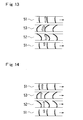
- Fig. 13 and Fig. 14 are views schematically showing the flow of an oil in a torque converter.
- a stator 53 serves to change the direction of flow of the oil so as to cause an impeller 51 to be further rotated, thereby to increase the torque as described above.
- t torque of output shaft / torque of input shaft
- speed ratio e When the speed ratio e is in a region smaller than the coupling point, the torque converter performs its torque increasing function, so that the torque ratio exceeds 1, and reaches its maximum of about 2 upon stalling when the output shaft is stopped. With the torque thus increased, the transmission efficiency ⁇ reaches its maximum just before the coupling point.
- the torque converter operates in a region where the speed ratio is larger than that of the coupling point.
- the torque converter operates in a region in which the speed ratio is small, so as to provide the torque increasing function.
- the actual frequency of use of each region is also influenced by the torque capacity.
- the torque capacity represents torque that can be received at a certain rotating speed. If this torque capacity is small, the frequency of use of a region having a relatively large torque ratio is increased with a result of improved accelerating performance, but the fuel economy is deteriorated. If the torque capacity is large, on the other hand, the frequency of use of a region having a relatively high transmission efficiency is increased, but the accelerating performance is deteriorated.
- the flow rate of the circulating oil needs to be increased, and the coupling point needs to be shifted as much as possible to the higher speed region where the larger speed ratio is obtained.
- each blade 53A of the stator needs to be oriented so as lie in the circumferential direction, to receive the flow of the oil smoothly.
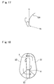
- the angle of the blade relative to the flow of the oil into the stator is increased upon stalling, as shown in Fig. 17, and the problem of flow separation occurs. As a result, the effective flow path area is reduced, and the flow rate of the circulating oil is lowered, resulting in reduction in the torque capacity coefficient.
- the blade of the stator is formed into a thin, wing-like shape so as to increase the area of the flow path, the flow separation at the time of stalling is more likely to occur. To avoid this, the number of blades may be increased to such an extent that does not significantly reduce the area of the flow path, so as to reduce the burden of each blade. In this case, however, the stator with the increased number of blades cannot be separated from a mold in the axial direction but must be separated in the radial direction, resulting in a more complicated manufacturing process and increased manufacturing cost.
- stator may be formed as a variable structure so that the angle of its blades is changed depending upon operating conditions, the structure becomes more complicated, resulting in reduced operating reliability and increased cost.
- the present invention provides a torque converter for a motor vehicle, comprising an impeller, a turbine, and a stator, for forming a circulation path of an oil and transmitting a rotary torque, each of the impeller, turbine and stator having a plurality of blades, wherein each blades of the stator is divided into a radially inner half portion and a radially outer half portion in a radial direction of the circulating path, and wherein the radially inner half portion has a front edge that is set back or staggered rearward from a front edge of the radially outer portion, and is inclined with respect to a direction of a rotation axis of the torque converter by a larger angle than the radially outer half portion.
- It may further comprise means for regulating an oil flow so as to suppress flow separation at said radially inner half portion.
- the radially inner half portion has a smaller thickness than the radially outer half portion, and a stepped portion is formed on a concave side of each blade, at a boundary between the radially inner half portion and the radially outer half portion.
- the boundary is preferably formed as a curved surface that extends substantially along a center line of the circulation path.
- each blade of at least one of the impeller and turbine has a radially inner half portion, a radially outer half portion, and a boundary fence that extends along the circulation path and separates the radially inner half portion and radially outer half portion from each other.
- the boundary fence may be formed as a stepped portion that rises from the radially inner half portion of each blade to the radially outer half portion, so that the radially outer half portion is offset from the radially inner half portion.
- the front edge of the radially outer half portion of each blade of the stator points to the direction of the rotation axis of the converter as compared with the front edge of the radially inner portion, to deal with the flow of the oil in the radially outer portion of the circulation path that determines the operating characteristics of the converter upon stalling. Accordingly, the flow separation is less likely to occur, and a large stall torque ratio and a large torque capacity can be obtained without reducing the effective flow path area. Further, the radially inner half portion of the stator blade makes a relatively small angle with respect to the circumferential direction of the circulation path in the large speed ratio region, whereby the coupling point is shifted to the higher speed side, and the transmission efficiency is improved.
- the stepped portion functions as a wall for regulating or rectifying the flow of the oil, thereby to prevent flow separation which would otherwise occur at the radially inner half portion.
- each blade of the impeller or turbine is provided with a boundary fence that separates its radially inner half portion and radially outer half portion from each other as described above, flow separation can be mostly prevented due to the flow regulating function of the boundary fence, and, even if flow separation occurs in a radially inner portion of the circulation path where the flow direction is suddenly changed, the turbulent flow due to the flow separation does not reach a radially outer portion of the circulation path.
- the boundary fence is formed as a stepped portion that rises from the radially inner half portion of each blade of the impeller or turbine to the radially outer half portion, so that the radially outer portion is offset from the radially inner portion, the boundary fence can be easily formed by press stamping. In this case, the rigidity of the blades is also improved.
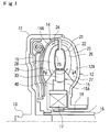
- Fig. 1 is a vertical cross sectional view showing the construction of one embodiment of the invention.
- a converter shell 11 is rotatably supported by a support shaft 18 provided on the side of a transmission case, and an impeller 12 is fixed to the converter shell 11.
- the output of an engine (not shown) is transmitted to an input shaft 13 of the converter shell 11.
- a turbine 14 is also disposed in the converter shell 11 such that its oil inlet side faces the oil outlet side of the impeller 12 in a radially outer portion of the converter shell 11. This turbine 14 is coupled to an input shaft 16 of a transmission that serves as an output shaft of the torque converter.
- a stator 15 is disposed between the oil outlet side of the turbine 14 and the oil inlet side of the impeller 12.
- the stator 15 is supported by the support shaft 18 via a one-way clutch 17.
- Blades of the impeller 12, turbine 14 and stator 15 have basic three-dimensional shapes known in the art. Thus, a circulation path is formed through which an oil flows in the direction of arrows in Fig. 1 when the impeller 12 is rotated.
- Cores 21, 25 are fixed to the impeller 12 and turbine 14, respectively, so as to increase the rigidity with which each blade array is mounted, and partially define the oil circulation path 20.
- a lockup clutch mechanism 19 is provided in the converter shell 11.
- the impeller 12 and turbine 14 are formed in flat shape so that the lockup clutch 19 can be housed in the converter shell 11 without increasing the axial length of the torque converter.
- Each blade 15A of the stator 15 is divided in its radial direction into two sections each having an approximately half size of the blade. These two sections will be called a radially inner half portion 30 and a radially outer half portion 40 as viewed in the circumferential direction of the oil circulation path.
- the boundary of the radially inner half portion 30 and radially outer half portion 40 is formed as a curved surface that substantially extends along the center line of the oil circulation path shown in the vertical cross section of Fig. 1.
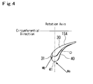
- Fig. 2 is an enlarged view of blades 15A of the stator 15 as seen in the direction of arrows A-A in Fig. 1.
- the radially outer half portion 40 has a front edge 41 that points to the same direction as the rotation axis R (input shaft 16) of the converter, and a rear edge 42 that is inclined toward the direction of rotation of the impeller 12.
- the radially outer half portion 40 has a wing-like shape with a certain camber for changing the direction of flow of the oil.
- the radially inner half portion 30 has a front edge 31 that is set back or staggered rearward from the front edge 41 of the radially outer half portion 40, and its rear face (convex face) extends along the curve of the rear face of the radially outer half portion.
- the radially inner half portion 30 has a smaller thickness than the radially outer half portion 40.
- the blade 15A also has a dog-tooth-like stepped portion D formed on its front face (concave face).
- each blade 12A, 14A of the impeller 12 and turbine 14 has a boundary stepped portion 22, 24 that extends in the direction of flow of the oil, substantially along the center line of the oil circulation path in the vertical cross section of Fig. 1.
- each blade of the impeller 12 and turbine 14 has a radially inner half portion 26, 28 from which the boundary stepped portion 22, 24 rises on the front side (concave side) of the blade, up to a radially outer half portion 27, 29.
- the stepped portion 22, 24 functions as a boundary fence for offsetting the radially outer half portion 27, 29 with respect to the radially inner half portion 26, 28 in the circulation path 20.
- Such boundary stepped portions 22, 24 are formed when the impeller 12 and turbine 14 are formed by press stamping.
- the flow rate of the circulating oil through the stator 15 is maximized in a torque increasing region, particularly when the vehicle is stalled with the speed ratio being zero. At this time, the flow speed is naturally greater in the radially outer portion of the circulation path, and therefore the flow of the oil through the radially outer portion of the stator substantially determines its operating characteristics.
- the front edge 31 of the radially inner half portion 30 is set back from the front edge 41, and the thickness of this portion 30 is reduced, so that the dog-tooth-like stepped portion D is formed at the boundary between the radially inner half portion 30 and the radially outer half portion 40.
- the dog-tooth-like stepped portion D provides a wall to regulate the flow of the oil, thereby to avoid the flow separation. Accordingly, a large stall torque ratio and a large torque capacity can be achieved without reducing the effective flow path area.
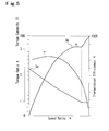
- the torque converter of the present embodiment exhibits operating characteristic curves as shown in the graph of Fig. 5. As is understood from this graph, an improved transmission efficiency as indicated by Sb is achieved while assuring a sufficiently large stall torque ratio as indicated by Sa.
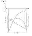
- the graph of Fig. 6 shows operating characteristic curves of a known prior art example in which each blade of the stator as a whole has the same shape as the radially outer portion of the stator blade of the present embodiment
- Fig. 7 shows operating characteristic curves of another known prior art example wherein each blade of the stator as a whole extends substantially in parallel with the circumferential direction of the circulation path.
- FIG. 8 shows characteristics of the present embodiment and the known examples, wherein solid lines are operating characteristic curves of the present embodiment, and one-dot chain lines are operating characteristic curves of the known example in which each blade as a whole substantially lies in the circumferential direction, while dotted lines are operating characteristic curves of the known example in which each blade as a whole has the same shape as the radially outer portion of the stator blade of the present embodiment.
- flow separation may occur due to their flat shapes, at the inlet portions of the impeller 12 and turbine 14 where the flow path is suddenly changed in direction. Even in this case, a speed component is prevented from arising in the direction from the radially inner portion to the radially outer portion, owing to the flow regulating function of the boundary stepped portions 22, 24 as boundary fences that are formed to extend in the flow direction, thus avoiding occurrence of flow separation. Even in the case where separation occurs at the edges of the radially inner portions, turbulent flow due to such separation does not reach the radially outer half portion 27, 29. Accordingly, the impeller 12 and turbine 14 having generally flat shapes assure sufficiently large torque ratio and large torque capacity, without reducing the effective flow path area.
- each blade of the stator 15 is divided into the radially inner half portion 30 and radially outer half portion 40, such that the front edge 41 of the radially outer half portion 40 points to substantially the same direction as the rotation axis of the converter as compared with the front edge 31 of the radially inner half portion 30, and such that the front edge 31 of the radially inner portion 30 is set back from the front edge 41 of the radially outer portion 40. Also, the thickness of the inner portion 30 is reduced.
- the torque converter with the stator thus constructed provides a high transmission efficiency in a region of large speed ratios, while assuring large stall torque ratio and large torque capacity.
- the impeller 12 and turbine 14 provided with the boundary fences (stepped portions) extending in the flow direction, flow separation is prevented from occurring at portions where the flow path is suddenly changed in direction, owing to the flow regulating function of the boundary fences. Accordingly, the axial length of the torque converter can be further reduced while assuring desired torque ratio and torque capacity. Further, since the boundary fences are provided by forming stepped portions by press stamping, the rigidity of the blades as a whole is also improved.
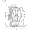
- Fig. 9 is a vertical cross sectional view showing the second embodiment of the present invention.
- the shape of each blade of a stator 15' is different from that of the stator 15 of the previous embodiment. More specifically, each blade 15A' of the stator 15' is shaped such that the boundary of its radially inner half portion 30' and radially outer half portion 40' in the circulation path extends in parallel with the rotation axis of the converter.
- the other parts of this embodiment are constructed in the same manner as in the first embodiment shown in Fig. 1.
- the stator with the blades 15A' thus shaped can be easily separated from a mold when it is formed by resin molding or casting.
- each blade of the stator, impeller and turbine is divided into a radially inner portion and a radially outer portion in the oil circulation path in the illustrated embodiments
- the present invention is not limited to this arrangement, but each blade may be divided into three or more sections.
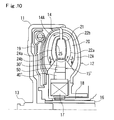
- Fig. 10 and Fig. 11 show a modified example of the second embodiment wherein each blade is divided into three sections.
- each blade 15A" of a stator 15" consists of a radially inner portion 30", middle portion 50, and a radially outer portion 40" that are arranged in the radial direction of the circulation path.
- An impeller 12" and a turbine 14" are formed with boundary stepped portions 22a, 22b and 24a, 24b, respectively.
- the oil circulation path is divided into three flow paths, namely, a radially inner path, middle path, and a radially outer path.
- a radially inner portion 30'" of the stator blade 15'" may be formed along the center line S of its radially outer portion 40'", as shown in Fig. 12.
- each blade of the stator is divided into a radially inner half portion and a radially outer half portion in the radial direction of the circulation path, and the front edge of the radially inner half portion is set back or staggered rearward from that of the radially outer half portion, so that the inner half portion forms a larger angle relative to the rotation axis of the converter than the outer half portion.
- the radially outer half portion whose front edge points to the direction of the rotation axis rather than that of the radially inner half portion effectively changes the direction of flow of the oil upon stalling, without causing flow separation, and thus assures increased stall torque ratio and torque capacity.
- the radially inner half portion of the stator blade is oriented so as to lie in the circumferential direction in the large speed ratio region, whereby the coupling point is shifted to the higher speed side, and the transmission efficiency is improved.
- the radially inner half portion has a smaller thickness than the radially outer half portion, and a stepped portion is formed at the boundary between the radially inner half portion and the radially outer half portion.
- the stepped portion serves as a wall for regulating or rectifying flow of the oil, so as to prevent flow separation which would otherwise occur at the radially inner half portion.
- each blade of the impeller or turbine is formed with a boundary fence that separates its radially inner half portion and radially outer half portion from each other.
- flow separation can be mostly prevented due to the flow regulating function of the boundary fence, and, even if flow separation occurs in a radially inner portion of the circulation path where the direction of flow is suddenly changed, turbulent flow due to the flow separation does not reach a radially outer portion of the circulation path.
- the torque converter can be small-sized by reducing the axial dimension thereof, without reducing the effective flow path area, while assuring sufficiently large torque ratio and torque capacity.
- the blade and boundary fence can be easily formed by press stamping.
- the rigidity of the blades is also advantageously improved.
Landscapes
- Engineering & Computer Science (AREA)
- General Engineering & Computer Science (AREA)
- Mechanical Engineering (AREA)
- Control Of Fluid Gearings (AREA)
- Hybrid Electric Vehicles (AREA)
Applications Claiming Priority (3)
| Application Number | Priority Date | Filing Date | Title |
|---|---|---|---|
| JP34054996 | 1996-12-05 | ||
| JP340549/96 | 1996-12-05 | ||
| JP8340549A JPH10169751A (ja) | 1996-12-05 | 1996-12-05 | 車両用トルクコンバータ |
Publications (3)
| Publication Number | Publication Date |
|---|---|
| EP0846894A2 true EP0846894A2 (de) | 1998-06-10 |
| EP0846894A3 EP0846894A3 (de) | 2000-04-12 |
| EP0846894B1 EP0846894B1 (de) | 2002-05-22 |
Family
ID=18338061
Family Applications (1)
| Application Number | Title | Priority Date | Filing Date |
|---|---|---|---|
| EP97309899A Expired - Lifetime EP0846894B1 (de) | 1996-12-05 | 1997-12-05 | Drehmomentwandler für Kraftfahrzeug |
Country Status (4)
| Country | Link |
|---|---|
| US (1) | US5836157A (de) |
| EP (1) | EP0846894B1 (de) |
| JP (1) | JPH10169751A (de) |
| DE (1) | DE69712717T2 (de) |
Cited By (3)
| Publication number | Priority date | Publication date | Assignee | Title |
|---|---|---|---|---|
| FR2784160A1 (fr) * | 1998-10-05 | 2000-04-07 | Mannesmann Sachs Ag | Stator de convertisseur hydrodynamique de couple |
| GB2344408A (en) * | 1998-10-05 | 2000-06-07 | Mannesmann Sachs Ag | Hydrodynamic torque converter impeller |
| FR2793293A1 (fr) * | 1999-05-05 | 2000-11-10 | Valeo | Appareil d'accouplement hydrocinetique a noyau de guidage en une ou deux parties |
Families Citing this family (9)
| Publication number | Priority date | Publication date | Assignee | Title |
|---|---|---|---|---|
| JPH1122805A (ja) * | 1997-07-07 | 1999-01-26 | Jatco Corp | ステータ構造 |
| KR20030050108A (ko) | 2001-12-18 | 2003-06-25 | 현대자동차주식회사 | 토크 컨버터용 스테이터 |
| US6996978B2 (en) * | 2004-05-05 | 2006-02-14 | Goerend David J | Torque converter stator |
| US7083381B2 (en) * | 2004-05-27 | 2006-08-01 | Ford Global Technologies, Llc | Hydrokinetic torque converter stator blade construction |
| KR100854115B1 (ko) | 2006-12-27 | 2008-08-26 | 한국파워트레인 주식회사 | 차량용 토크컨버터 |
| DE102008020673B4 (de) | 2007-05-09 | 2018-10-31 | Schaeffler Technologies AG & Co. KG | Abgestufte Statorschaufel |
| US20110311367A1 (en) * | 2009-02-17 | 2011-12-22 | Exedy Corporation | Stator and torque converter |
| US20150252883A1 (en) * | 2014-03-06 | 2015-09-10 | Schaeffler Technologies AG & Co. KG | Radial split stator |
| US12612961B1 (en) * | 2025-02-18 | 2026-04-28 | Schaeffler Technologies AG & Co. KG | Hatless stator |
Family Cites Families (9)
| Publication number | Priority date | Publication date | Assignee | Title |
|---|---|---|---|---|
| US1904054A (en) * | 1930-11-11 | 1933-04-18 | Kiep Johann Nikolaus | Hydraulic coupling |
| US2393470A (en) * | 1943-08-28 | 1946-01-22 | Bendix Aviat Corp | Fluid transmission |
| US2917001A (en) * | 1951-06-16 | 1959-12-15 | Borg Warner | Hydrodynamic coupling |
| US2821839A (en) * | 1954-04-24 | 1958-02-04 | Renault | Hydraulic torque converters |
| GB859955A (en) * | 1956-12-27 | 1961-01-25 | Borg Warner | Hydraulic torque converter |
| US3167917A (en) * | 1960-09-07 | 1965-02-02 | Alexander M Alexandrescu | Hydraulic coupling |
| US4009571A (en) * | 1976-01-30 | 1977-03-01 | Twin Disc, Incorporated | Torque converter having adjustably movable stator vane sections and actuator means therefor |
| US5522220A (en) * | 1991-12-23 | 1996-06-04 | Ford Motor Company | High efficiency blade |
| JP3086377B2 (ja) * | 1994-06-16 | 2000-09-11 | 本田技研工業株式会社 | トルクコンバータのステータ構造 |
-
1996
- 1996-12-05 JP JP8340549A patent/JPH10169751A/ja not_active Withdrawn
-
1997
- 1997-12-04 US US08/985,340 patent/US5836157A/en not_active Expired - Fee Related
- 1997-12-05 DE DE69712717T patent/DE69712717T2/de not_active Expired - Fee Related
- 1997-12-05 EP EP97309899A patent/EP0846894B1/de not_active Expired - Lifetime
Non-Patent Citations (1)
| Title |
|---|
| None |
Cited By (8)
| Publication number | Priority date | Publication date | Assignee | Title |
|---|---|---|---|---|
| FR2784160A1 (fr) * | 1998-10-05 | 2000-04-07 | Mannesmann Sachs Ag | Stator de convertisseur hydrodynamique de couple |
| GB2344408A (en) * | 1998-10-05 | 2000-06-07 | Mannesmann Sachs Ag | Hydrodynamic torque converter impeller |
| GB2344636A (en) * | 1998-10-05 | 2000-06-14 | Mannesmann Sachs Ag | Guide wheel for a hydrodynamic torque converter |
| US6226985B1 (en) | 1998-10-05 | 2001-05-08 | Mannesmann Sachs Ag | Impeller wheel arrangement and turbine wheel arrangement for a hydrodynamic torque converter |
| US6266958B1 (en) | 1998-10-05 | 2001-07-31 | Mannesmann Sachs Ag | Stator wheel for a hydrodynamic torque converter |
| GB2344408B (en) * | 1998-10-05 | 2002-09-18 | Mannesmann Sachs Ag | Hydrodynamic torque converter and impellers therefor |
| GB2344636B (en) * | 1998-10-05 | 2003-07-16 | Mannesmann Sachs Ag | Guide wheel for a hydrodynamic torque converter |
| FR2793293A1 (fr) * | 1999-05-05 | 2000-11-10 | Valeo | Appareil d'accouplement hydrocinetique a noyau de guidage en une ou deux parties |
Also Published As
| Publication number | Publication date |
|---|---|
| EP0846894B1 (de) | 2002-05-22 |
| US5836157A (en) | 1998-11-17 |
| JPH10169751A (ja) | 1998-06-26 |
| EP0846894A3 (de) | 2000-04-12 |
| DE69712717T2 (de) | 2003-01-30 |
| DE69712717D1 (de) | 2002-06-27 |
Similar Documents
| Publication | Publication Date | Title |
|---|---|---|
| US5836157A (en) | Torque converter for motor vehicle | |
| US4848084A (en) | Hydrodynamic torque converter having variable stator plate orifice | |
| EP0232622B2 (de) | Hydraulischer Drehmomentwandler | |
| US6003311A (en) | Stator blade of torque converter | |
| US5966934A (en) | Torque converter for motor vehicle | |
| JP3884119B2 (ja) | トルクコンバータのインペラシェル | |
| US5640849A (en) | Stator assembly for a fluid torque converter | |
| US6216454B1 (en) | Torque converter | |
| US6860102B2 (en) | Stator for a torque converter of a vehicle | |
| US5271716A (en) | Coreless torque converter | |
| US6996978B2 (en) | Torque converter stator | |
| JPH0579545A (ja) | コアレストルクコンバータ | |
| US20040118113A1 (en) | Torque converter | |
| US5313794A (en) | Fluid coupling | |
| US6745563B1 (en) | Axially reduced torque converter with axial pull stator | |
| EP0503692A1 (de) | Pumpenrad für einen Drehmomentwandler | |
| JP3298314B2 (ja) | トルクコンバータ | |
| US20040118112A1 (en) | Torque converter | |
| JP4487404B2 (ja) | トルクコンバータ | |
| JP3028499B2 (ja) | トルクコンバータの調整方法 | |
| JP2945408B2 (ja) | トルクコンバータ | |
| JP3246523B2 (ja) | トルクコンバータ | |
| JP3168668B2 (ja) | トルクコンバータのステータブレード | |
| JP3246524B2 (ja) | トルクコンバータ | |
| JPH10169753A (ja) | トルクコンバータ |
Legal Events
| Date | Code | Title | Description |
|---|---|---|---|
| PUAI | Public reference made under article 153(3) epc to a published international application that has entered the european phase |
Free format text: ORIGINAL CODE: 0009012 |
|
| AK | Designated contracting states |
Kind code of ref document: A2 Designated state(s): DE FR GB |
|
| AX | Request for extension of the european patent |
Free format text: AL;LT;LV;MK;RO;SI |
|
| PUAL | Search report despatched |
Free format text: ORIGINAL CODE: 0009013 |
|
| AK | Designated contracting states |
Kind code of ref document: A3 Designated state(s): AT BE CH DE DK ES FI FR GB GR IE IT LI LU MC NL PT SE |
|
| AX | Request for extension of the european patent |
Free format text: AL;LT;LV;MK;RO;SI |
|
| 17P | Request for examination filed |
Effective date: 20000630 |
|
| 17Q | First examination report despatched |
Effective date: 20000811 |
|
| AKX | Designation fees paid |
Free format text: DE FR GB |
|
| GRAG | Despatch of communication of intention to grant |
Free format text: ORIGINAL CODE: EPIDOS AGRA |
|
| GRAG | Despatch of communication of intention to grant |
Free format text: ORIGINAL CODE: EPIDOS AGRA |
|
| GRAH | Despatch of communication of intention to grant a patent |
Free format text: ORIGINAL CODE: EPIDOS IGRA |
|
| GRAH | Despatch of communication of intention to grant a patent |
Free format text: ORIGINAL CODE: EPIDOS IGRA |
|
| GRAA | (expected) grant |
Free format text: ORIGINAL CODE: 0009210 |
|
| PG25 | Lapsed in a contracting state [announced via postgrant information from national office to epo] |
Ref country code: FR Free format text: LAPSE BECAUSE OF FAILURE TO SUBMIT A TRANSLATION OF THE DESCRIPTION OR TO PAY THE FEE WITHIN THE PRESCRIBED TIME-LIMIT Effective date: 20020522 |
|
| REG | Reference to a national code |
Ref country code: GB Ref legal event code: FG4D |
|
| REF | Corresponds to: |
Ref document number: 69712717 Country of ref document: DE Date of ref document: 20020627 |
|
| PG25 | Lapsed in a contracting state [announced via postgrant information from national office to epo] |
Ref country code: GB Free format text: LAPSE BECAUSE OF NON-PAYMENT OF DUE FEES Effective date: 20021205 |
|
| EN | Fr: translation not filed | ||
| PLBE | No opposition filed within time limit |
Free format text: ORIGINAL CODE: 0009261 |
|
| STAA | Information on the status of an ep patent application or granted ep patent |
Free format text: STATUS: NO OPPOSITION FILED WITHIN TIME LIMIT |
|
| 26N | No opposition filed |
Effective date: 20030225 |
|
| PG25 | Lapsed in a contracting state [announced via postgrant information from national office to epo] |
Ref country code: DE Free format text: LAPSE BECAUSE OF NON-PAYMENT OF DUE FEES Effective date: 20030701 |
|
| GBPC | Gb: european patent ceased through non-payment of renewal fee |